EP0461673A2 - Informationsabtaster - Google Patents
Informationsabtaster Download PDFInfo
- Publication number
- EP0461673A2 EP0461673A2 EP91109815A EP91109815A EP0461673A2 EP 0461673 A2 EP0461673 A2 EP 0461673A2 EP 91109815 A EP91109815 A EP 91109815A EP 91109815 A EP91109815 A EP 91109815A EP 0461673 A2 EP0461673 A2 EP 0461673A2
- Authority
- EP
- European Patent Office
- Prior art keywords
- light beam
- hologram disk
- information reader
- reflected
- reader according
- Prior art date
- Legal status (The legal status is an assumption and is not a legal conclusion. Google has not performed a legal analysis and makes no representation as to the accuracy of the status listed.)
- Withdrawn
Links
Images







Classifications
-
- G—PHYSICS
- G06—COMPUTING OR CALCULATING; COUNTING
- G06K—GRAPHICAL DATA READING; PRESENTATION OF DATA; RECORD CARRIERS; HANDLING RECORD CARRIERS
- G06K7/00—Methods or arrangements for sensing record carriers, e.g. for reading patterns
- G06K7/10—Methods or arrangements for sensing record carriers, e.g. for reading patterns by electromagnetic radiation, e.g. optical sensing; by corpuscular radiation
- G06K7/10544—Methods or arrangements for sensing record carriers, e.g. for reading patterns by electromagnetic radiation, e.g. optical sensing; by corpuscular radiation by scanning of the records by radiation in the optical part of the electromagnetic spectrum
- G06K7/10821—Methods or arrangements for sensing record carriers, e.g. for reading patterns by electromagnetic radiation, e.g. optical sensing; by corpuscular radiation by scanning of the records by radiation in the optical part of the electromagnetic spectrum further details of bar or optical code scanning devices
- G06K7/10861—Methods or arrangements for sensing record carriers, e.g. for reading patterns by electromagnetic radiation, e.g. optical sensing; by corpuscular radiation by scanning of the records by radiation in the optical part of the electromagnetic spectrum further details of bar or optical code scanning devices sensing of data fields affixed to objects or articles, e.g. coded labels
- G06K7/10871—Methods or arrangements for sensing record carriers, e.g. for reading patterns by electromagnetic radiation, e.g. optical sensing; by corpuscular radiation by scanning of the records by radiation in the optical part of the electromagnetic spectrum further details of bar or optical code scanning devices sensing of data fields affixed to objects or articles, e.g. coded labels randomly oriented data-fields, code-marks therefore, e.g. concentric circles-code
-
- G—PHYSICS
- G06—COMPUTING OR CALCULATING; COUNTING
- G06K—GRAPHICAL DATA READING; PRESENTATION OF DATA; RECORD CARRIERS; HANDLING RECORD CARRIERS
- G06K7/00—Methods or arrangements for sensing record carriers, e.g. for reading patterns
- G06K7/10—Methods or arrangements for sensing record carriers, e.g. for reading patterns by electromagnetic radiation, e.g. optical sensing; by corpuscular radiation
- G06K7/10544—Methods or arrangements for sensing record carriers, e.g. for reading patterns by electromagnetic radiation, e.g. optical sensing; by corpuscular radiation by scanning of the records by radiation in the optical part of the electromagnetic spectrum
- G06K7/10554—Moving beam scanning
- G06K7/10594—Beam path
- G06K7/10603—Basic scanning using moving elements
- G06K7/10663—Basic scanning using moving elements using hologram
-
- G—PHYSICS
- G06—COMPUTING OR CALCULATING; COUNTING
- G06K—GRAPHICAL DATA READING; PRESENTATION OF DATA; RECORD CARRIERS; HANDLING RECORD CARRIERS
- G06K7/00—Methods or arrangements for sensing record carriers, e.g. for reading patterns
- G06K7/10—Methods or arrangements for sensing record carriers, e.g. for reading patterns by electromagnetic radiation, e.g. optical sensing; by corpuscular radiation
- G06K7/10544—Methods or arrangements for sensing record carriers, e.g. for reading patterns by electromagnetic radiation, e.g. optical sensing; by corpuscular radiation by scanning of the records by radiation in the optical part of the electromagnetic spectrum
- G06K7/10554—Moving beam scanning
- G06K7/10594—Beam path
- G06K7/10683—Arrangement of fixed elements
- G06K7/10693—Arrangement of fixed elements for omnidirectional scanning
Definitions
- the present invention relates to an information reader.
- the information reader is utilized as, for instance, a bar code reader.
- the bar code reader uses a hologram disk for reading the bar code of a bar code label attached to goods to be monitored.
- Conventional overhead type bar code readers incorporate a scanning unit placed above a path of movement of the goods.
- the scanning unit has a light source, a scanning system, and a sensing system.
- the light source emits a scanning light beam downward to read the bar code.
- the overhead-type bar code reader described in U.S. Patent Application Serial No. 562,865 filed on August 6, 1990 (corresponding to Japanese Patent Application No. Heisei 1-203648) was proposed.
- a light blocking tube is provided in a condenser lens which collects the laser beam reflected by the bar code label.
- the light blocking tube extends through the condenser lens along the central optical axis of the condenser lens.
- a laser beam emitted from a light source is reflected by a reflecting mirror provided on the light blocking tube in a direction to advance along the longitudinal axis of the light blocking tube.
- the reflected laser beam impinges on a hologram disk at a right angle.
- the optical path length in the scanning unit of this bar code reader is shortened because the condenser lens as a light-collecting means is disposed near the hologram disk.
- the reflecting mirror and the light source are separately installed in the scanning unit. Therefore, it is easy to misalign the optical axes of the reflecting mirror and the light source.
- the incidence angle of the reflected laser beam on the hologram disk deviates from perpendicular.
- the incidence angle of a light beam on the hologram disk need to be adjusted with high accuracy. This is because the incidence angle has a large effect on the diffraction efficiency of the hologram disk. For instance, when the incidence angle is an unsuitable angle, optical intensity emitted from the hologram disk becomes weak. In such a case, the above-mentioned bar code reader can not read the bar code information accurately.
- Another objective of the present invention is to reduce the size of the information reader.
- Still another objective of the present invention is to reduce optical noise.
- an information reader which includes a light source for emitting a light beam.
- a detecting means detects the light beam after it is reflected from an article on which readable information exists.
- a scanning mean scans the light beam in two dimensions and guides the light beam reflected to the detecting means.
- a deflecting means deflects the light beam emitted from the light source toward the scanning means.
- the light source, the detecting means the scanning means and the deflecting means are all installed within a housing.
- the light source and the deflecting means are integrally detachable to the housing. It is thus easy to adjust the incidence angle of the light beam on the scanning means.
- Fig. 1 illustrates an overhead-type bar code reader of the present invention as it is disposed on a cash register counter.
- the cash register counter includes a counter table 1 on which a scanning unit 2 of the bar code reader is supported by a support unit 3.
- the scanning unit 2 is electrically connected with a control circuit 4 by a cable 4a extending through the support unit 3.
- a reading signal corresponding to information on a bar code is transferred from the scanning unit 2 to the control circuit 4 through the cable 4a.
- the support unit 3 includes a base 31, a first tubular support column 32, and a second tubular support column 33.
- the base 31 is secured to the counter table 1.
- the first tubular support column 32 is fixed to and upstanding from the base 31.
- the second tubular support column 33 is slidably received in the first tubular support column 32.
- the base 31 has a plurality of holes 36 through which screw fasteners (not shown) extend to mount the bar code reader on the counter table 1.
- the second support column 33 is vertically movable in the first support column 32 and can be locked at any desired position by a set screw 34.
- the scanning unit 2 is pivoted to an upper end of the second support column 33 and is pivotally movable in a vertical plane about a horizontal axis 35.
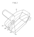
- Fig. 2 illustrates the scanning unit 2 as viewed from the upper left thereof.
- the scanning unit 2 includes a housing 22 composed of an upper case 22a and a lower case 22b joined together.
- the scanning unit 2 has a reading window 21 in the lower case 22b and a display window 23 in the upper case 22a.
- the reading window 21 is closed by transparent glass 21a.
- the transparent glass 21a is installed on the lower case 22b at a predetermined angle so that it does not unnecessarily reflect a laser beam passing therethrough.
- the display window 23 includes a colored transparent plastic plate.
- a light emitting diode (LED) 23a and another light emitting diode (LED) 23b are disposed in the housing 22 below the display window 23 for indicating the power-on state and the fault bar code reading operation, respectively.
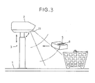
- the bar code reader of the invention is used in the condition as shown in Fig. 3.
- the scanning unit 2 disposed over the counter table 1 emits the laser beam through a reading window 21 onto a path of travel of goods at an angle of approximately 45 degrees toward an incoming good 5 so as to scan with the laser beam a zone defined between two-dotted chain lines.
- a bar code 6 which is generally printed on the surface of a bar code label attached to the outer surface of the good 5 is read.
- the information on the bar code thus read is decoded by the control circuit 4 and then delivered to a POS(point-of-sale) terminal device (not shown) for the calculation of the volume of sales, etc.
- a frame 200a and a frame 200b are fixed in the scanning unit 2 and connect to the second support column 33.
- the frame 200a and the frame 200b constitute a mechanical frame and has a high rigidity in view of the required accuracy of an optical system. It is noted that the frame 200a and the frame 200b are formed as one member.
- a circular hologram disk 205 has formed thereon a first hologram 205a and a second hologram 205b which have different focal lengths and different diffraction angles.
- Each of the first and second holograms 205a, 205b circumferentially extend over an angle of 180 degrees.
- the holograms 205a, 205b respectively diffract and converge the laser beam impinging thereon.
- a scanning pattern 220 shown in Fig. 6 includes five pairs of spaced scanning lines 220a-220e. Each scanning line pair is formed by one of five flat reflecting mirrors 207a-207e.
- the reflecting mirrors 207a-207e are arranged side-by-side juxtaposition and have one side (lower side) open.
- One of each pair of the scanning lines 220a-220e is formed by the first hologram 205a, while the other of each pair of the scanning lines 220a-220e is formed by the second hologram 205b.
- the hologram disk 205 is rotated by a motor 206 whereupon each of the first and second holograms 205a, 205b diffracts the laser beam passing therethrough and lets the outgoing laser beam scan a semicircular range extending through an angle of 180 degrees. Subsequently the reflected laser beam passes through the reading window 21.
- the respective reflecting mirrors 207a-207e are fixedly supported by the frame 200a the scanning pattern and the number of scanning lines can be changed by replacing the polygonal reflecting mirror assembly 207 with another polygonal reflecting mirror assembly having three, four or six reflecting mirrors.
- the hologram disk 205 is fixedly mounted on a shaft of the motor 206.
- the shaft extends through the frame 200b, a motor base 206a and a motor support member 206b.
- the hologram disk 205 is received in a recess formed by the frame 200b and an optical-system support substrate 203 is placed over the recess to function as a lid.
- the hologram disk 205 thus received is protected from contamination by dust or dirt and is also prevented from flying out when it is broken.
- the motor 206 is of the outer rotor type and is mounted on the frame 200b together with the motor base 206a and the motor support member 206b.
- a light blocking plate 208 extends from the frame 200b for shielding or blocking light which is transmitted between the holograms and the reading window 21.
- a photo-interrupter 212 is disposed on the frame 200b at a predetermined position.
- the photo-interrupter 212 is composed of a light emitting element 212a and a light sensitive element 212b confronting each other across the thickness of the hologram disk 205.
- the hologram disk 205 is provided with a plurality of circumferentially spaced opaque marks 205c at positions corresponding in position to the leading ends (start) and the trailing ends (end) of the respective scanning lines.
- the marks 205c are detected by the photo-interrupter 212 so that the leading and trailing ends of each scanning line are detected.
- One of the marks 205c (the bottom mark in the illustrated embodiment) is wider than the remainder.
- Each revolution of the hologram disk 205 is detected by monitoring a longer duration of a detected pulse signal supplied from the photo-interrupter 212 when the wider mark 205c intersects the photo-interrupter 212.
- the optical-system support substrate 203 is fixed at the ends of the frame 200a and the frame 200b so that the support substrate 203 is parallel to the hologram disk 205.
- the support substrate 203 fixes a condenser lens 202, a sensing system 204, and an incidence optical-system support substrate 215 thereon.
- the condenser lens 202 collects the laser beam reflected by the bar code label.
- the sensing system 205 receives the reflected laser beam collected by the condenser lens 202 and obtains an electric signal in accordance with bars and spaces of the bar code 6.
- the support substrate 215 fixes a semiconductor laser beam source 201 and a prism 209 thereon.
- the semiconductor laser beam source 201 includes a laser diode and a lens system therein.
- the laser diode emits a visible laser beam L.
- the emitted laser beam L is a collimated or parallel beam of light.
- the laser beam L advances along the longitudinal axis of the prism 209.
- the prism 209 is formed from transparent material such as glass and has an elongate structure.
- a first end of the prism 209 is connected to the exit hole of the semiconductor laser beam source 201 for guiding the laser beam to a position immediately beneath the condenser lens 202.
- a second end of the prism 209 is oblique at an angle of 45 degrees to the longitudinal axis of the prism 209 for totally reflecting the laser beam L toward the hologram disk 205.
- the reflected laser beam L is then emitted at an approximately right angle to the longitudinal axis of the prism 209 and impinges upon the hologram disk 205.
- a reflecting mirror 210 reflects the collected laser beam by the condenser lens 202 toward a photo-detector 211 through a band pass filter 213. The reflected laser beam is then focussed on the photo-detector 211.
- the band pass filter 213 is installed in front of the photo-detector 211 and transmits only the laser beam having a predetermined band of wavelength to the photo-detector 211.
- the photo-detector 211 produces a train of electric pulses in accordance with the optical intensity of the laser beam.
- the train of electric pulses is decoded by a decode circuit (not shown) and thereafter is applied to the control circuit 4. It is noted that a decoded signal may be directly applied to any suitable alternative system such as a POS terminal device.
- the power LED 23a When a power switch (not shown) is turned on, the power LED 23a is turned on and the hologram disk 205 is rotated by the motor 206.
- the rotational speed of the hologram disk 205 is increased to such an extent that the rotating hologram disk 205 can scan a laser beam at sufficiently high speeds. Thereafter, the hologram disk 205 is kept in a steady-state rotation.
- the laser beam is then generated by the semiconductor laser beam source 201.
- the rotational speed of the hologram disk 205 slows down, the generation of the laser beam is interrupted so as to prevent a particular point from being irradiated with the laser beam for a prolonged period of time.
- the laser beam is then totally reflected by the oblique end of the prism 209 so that it impinges upon the hologram disk 205 at an approximately right angle.
- the laser beam is diffracted by the first hologram 205a and the second hologram 205b.
- the diffracted laser beam is then reflected by the polygonal reflecting mirror assembly 207.
- the reflected laser beam forms a scanning beam focussed on a position which is spaced from the reading window 21 by a predetermined distance.
- the scanning beam thus formed moves in the scanning pattern shown in Fig. 6 as the hologram disk 205 rotates.
- the scanning laser beam is reflected by the bar code label.
- the intensity of the reflected laser beam changes in accordance with the reflectance of the individual bars and spaces therebetween.
- the reflected laser beam goes back toward the hologram disk 205 along the same path as the scanning laser beam has passed and impinges upon the holograms 205a, 205b. Thereafter, the reflected laser beam passes through the condenser lens 202 and the band pass filter 213 and impinges upon the photo-detector 211.
- the photo-detector 211 in turn produces a train of electric pulse signals which are equivalent to the information on the bar code of the bar code label.
- the photo-interrupter 212 issues timing signals indicative of the leading and trailing ends of each scanning line 220a-220e.
- the electric pulse signals from the photo-detector 211 are separated and discriminated as signals obtained by reflection from the respective scanning lines 220a-220e.
- this train of electric pulse signals is decoded and the output signals are then transmitted to a central processing unit incorporated in the control circuit 4 (Fig. 4).
- the bar code reader is of the overhead-type in which the scanning unit 2 is disposed above the path of movement of the good 5, the cashier is able to observe the bar code while the bar code is being read by the bar code reader. Moreover, the bar code reader is able to perform a multi-directional scanning.
- the scanning unit 2 be compact in size.
- the scanning unit 2 of the present embodiment incorporates various structural features which are contributive to the reduction of the overall size of the scanning unit 2, as described below.
- the hologram disk 205 is disposed obliquely in the scanning unit 2 so that the overall height of the scanning unit is relatively small.
- the first and second holograms 205a, 205b each extend over an angle of 180 degrees about the center of the hologram disk 205 (namely, each hologram 205a, 205b extends along half of the full circumference of the hologram disk 205) and hence scan the laser beam within a semicircular range extending over an angle of 180 degrees.
- the polygonal reflecting mirror assembly 207 disposed behind the hologram disk 205 for the formation of the scanning pattern extends substantially along half of the full circumference of the hologram disk 205 (that is, within an angular range of 180 degrees).
- the motor 206 for driving the hologram disk 205 can be disposed on the open side of the polygonal reflecting mirror assembly 207 within the range of a complementary angle of 180 degrees of the same circle. This arrangement of the motor 206 helps reduce the size of the scanning unit 2. Moreover, since the motor 206 is disposed below the polygonal reflecting mirror assembly 207, the center of gravity of the bar code reader is relatively low.
- the optical system of the scanning unit 2 preferably is as simple as possible.
- the scanning laser beam diffracted by the holograms 205a, 205b is reflected just once by the polygonal reflecting mirror assembly 207 before it leaves the scanning unit 2. Accordingly, the laser beam incident upon the holograms 205a, 205b is necessarily directed toward the reading window 21.
- the laser beam which is directed from the semiconductor laser beam source 201 onto the hologram disk 205 may contain a transmitted light component which makes a straight advance to the reading window 21 without being diffracted by the holograms 205a, 205b and directly goes out from the reading window 21.
- the transmitted light component is reflected by the good, the reflected transmitted light component may be detected by the photo-detector 211 as an optical noise.
- any such a transmitted light component is blocked by the light blocking plate 208 before it reaches the good 5.
- the light blocking plate 208 is substantially facing the opening area of the condenser lens 202 so that light coming from the reading window 21 into the scanning unit 2 is prevented from arriving directly at the photo-detector 211. Rather, light incident upon the photo-detector 211 is limited to the light which is reflected by one of the reflecting mirrors 207a-207e and thereafter diffracted by one of the holograms 205a, 205b. Thus, a considerable reduction of the optical noise is attained.
- the hologram disk 205 does not have significant focusing ability. Therefore, the hologram disk 205 can not itself focus the laser beam reflected by the bar code label be focussed on the photo-detector 211.
- the reflected laser beam is focussed by the condenser lens 202 disposed between the hologram disk 205 and the photo-detector 211.
- the laser beam incident upon this hologram disk must be divergent light.
- the laser beam may be a collimated or parallel beam of light. Thus, the degree of freedom for the kind of the incident light is extended.
- the scanning unit 2 When the scanning unit 2 is used with a parallel beam of light, a certain degree of misalignment is permitted between the laser beam source 201 and the hologram disk 205. This is because the parallel beam of light may impinge upon any position of the hologram disk 205 thereby insuring a maximum diffraction efficiency. Consequently, an error which may occur in assembling the condenser lens 202 with the support substrate 203 is accommodated.
- the bar code reader is assembled without difficulty.
- the scanning unit 2 becomes large because the optical path length between the hologram disk 205 and a focal point becomes long.
- the scanning unit 2 can be small because the optical path length can be short.
- Outer endmost two reflecting mirrors 207a and 207e of the polygonal reflecting mirror assembly 207 are larger in width than the middle reflecting mirrors 207b, 207c and 207d and extend downward beyond the angular range of 180 degrees stated above. Therefore the light collecting ability is compensated when the reflected light produced along the scanning lines corresponding to the endmost two reflecting mirrors 207a, 207e is collected.
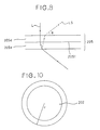
- the radius of the condenser lens 202 is in a range of less than a predetermined radius so as to prevent an unwanted laser beam L5 (shown in Fig. 8) from being sensed by the sensing system 204. Therefore, optical noise sensed by the sensing system 204 is reduced.
- a suitable radius for the condenser lens 202 will be explained below with reference to Figs. 8-10.
- the hologram disk 205 is composed of glass layers 205d, 205e and a gelatin layer 205f interposed therebetween.
- the laser beam L emitted from the prism 209 impinges upon the hologram disk 205, a part of the laser beam L is reflected at a surface of the glass layer 205e, and further, it is diffracted at a surface of the glass layer 205d.
- the unwanted laser beam L5 is emitted from the hologram disk 205 toward the condenser lens 202.
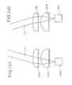
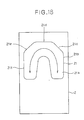
- Figs. 11A-11C, 12A, and 12B show the construction on the support substrate 215 installing the semiconductor laser beam source 201, the prism 209, and a driving circuit 216. It is noted that screw for fixing the support substrate 215 are omitted in these Figs.
- the prism 209 is fastened between a support member 209a and a blade spring 209b.
- the support member 209a is fixed on the support substrate 215 with such as screws.
- the blade spring 209b is fixed on the support member 209a with such as screws.
- the driving circuit 216 is for driving a laser diode 201b shown in Fig. 13.
- the semiconductor laser beam source 201 is fixed on the support substrate 215 with such as screws.
- An adjustment mechanism 201a is provided in first end of the semiconductor laser beam source 201, the first end being opposite to the second end from which the laser beam L is emitted.
- the laser diode 201b is moved in a vertical direction and a horizontal direction by the adjustment mechanism 201a for emitting the laser beam from the prism 209 at an approximately right angle to the longitudinal axis of the prism 209.
- a first meniscus lens 201d and a second meniscus lens 201e are fixed in a housing 201c by a movable member 201f and a lens-fixing member 201g disposed in the movabe member 201f.
- the movable member 201f is movably intervened between a coil spring 201h and a focus-adjusting screw 2011.
- the movable member 201f approaches or leaves the laser diode 201b in accordance with the rotation of the focus-adjusting screw 2011. Therefore, the first meniscus lens 201d and the second meniscus lens 201e is moved with the movable member 201f for adjusting the focal point of the laser beam L.
- An outgoing angle of the laser beam L emitted from the prism 209 is adjusted by the adjustment mechanism 201a so that the laser beam L impinges upon the hologram disk 205 at an approximately right angle.
- the adjustment of the outgoing angle is simultaneously carried out in vertical and horizontal directions by an autocollimator.
- the support substrate 215 is installed on an optical table installed in a horizontal direction.
- the prism 209 and the semiconductor laser beam source 201 have already been assembled on the support substrate 215.
- the laser beam L is then emitted from the prism 209 toward the auto collimator installed in a vertical direction.
- the emitted laser beam L appears as a luminous point in the visual field of the autocollimator.
- the position of the laser diode 201b is adjusted by the adjustment mechanism 201a so that the luminous point is on the center of crosshairs which has already been drawn in the visual field.
- the laser beam L is emitted to the optical table at a right angle.
- the adjustment for impinging the laser beam L upon the hologram disk 205 at a right angle is carried out.
- the adjustment of the outgoing angle of the laser beam is carried out when the semiconductor laser beam source 201 and the prism 209 are installed on the support substrate 215. Therefore, when the support substrate 215 is assembled in the scanning unit 2, the laser beam impinges upon the hologram disk 205 at a right angle by only fixing the support substrate 203 at the ends of the frame 200a and the frame 200b without adjustment of the outgoing angle of the laser beam.
- the support substrate 215 fixing the semiconductor laser beam source 201 and the prism 209 is fixed by the support substrate 203. Therefore, the semiconductor laser beam source 201 and the prism 209 are detachably installed in the scanning unit 2.
- the prism 209 formed from transparent material is utilized as a deflecting member for deflecting the laser beam emitted from the semiconductor laser beam source 201. Therefore, when the laser beam transmits in the prism 209, the quantity of light of the laser beam which reaches the photo-detector 211 is hardly reduced. As a result, the photo-detector 211 detects the laser beam having the sufficient quantity of light and the sensitivity of the photo-detector 211 becomes high.
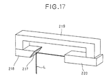
- Fig. 16 shows another embodiment of the deflecting member.
- a stay 38 is disposed under a condenser lens 41.
- the stay 38 is formed from opaque material.
- a reflecting member 37 is connected to one end of the stay 38.
- a laser beam L emitted from a laser beam source 39 is reflected by the reflecting member 37 and impinges upon a hologram disk 40 at an approximately right angle.
- the laser beam L is blocked by the stay 38 formed from opaque material. The quantity of light of the laser beam which reaches the photo-detector 211 is reduced.
Landscapes
- Physics & Mathematics (AREA)
- Electromagnetism (AREA)
- Engineering & Computer Science (AREA)
- Health & Medical Sciences (AREA)
- General Health & Medical Sciences (AREA)
- Toxicology (AREA)
- Artificial Intelligence (AREA)
- Computer Vision & Pattern Recognition (AREA)
- General Physics & Mathematics (AREA)
- Theoretical Computer Science (AREA)
- Mechanical Optical Scanning Systems (AREA)
Applications Claiming Priority (4)
| Application Number | Priority Date | Filing Date | Title |
|---|---|---|---|
| JP158390/90 | 1990-06-15 | ||
| JP15839090 | 1990-06-15 | ||
| JP38779/90 | 1991-03-05 | ||
| JP3038779A JP2751644B2 (ja) | 1990-06-15 | 1991-03-05 | 光走査装置 |
Publications (2)
| Publication Number | Publication Date |
|---|---|
| EP0461673A2 true EP0461673A2 (de) | 1991-12-18 |
| EP0461673A3 EP0461673A3 (en) | 1992-09-23 |
Family
ID=26378065
Family Applications (1)
| Application Number | Title | Priority Date | Filing Date |
|---|---|---|---|
| EP19910109815 Withdrawn EP0461673A3 (en) | 1990-06-15 | 1991-06-14 | Information reader |
Country Status (3)
| Country | Link |
|---|---|
| US (1) | US5291007A (de) |
| EP (1) | EP0461673A3 (de) |
| AU (1) | AU643026B2 (de) |
Cited By (4)
| Publication number | Priority date | Publication date | Assignee | Title |
|---|---|---|---|---|
| EP0686930A1 (de) * | 1994-06-08 | 1995-12-13 | Scantech B.V. | Vorrichtung zum Abtasten kodierter Information |
| NL1003957C2 (nl) * | 1996-02-26 | 1997-08-27 | Scantech Bv | Inrichting voor het aftasten van barcodes. |
| EP0837415A1 (de) * | 1996-10-14 | 1998-04-22 | Opticon Sensors Europe B.V. | Abtastsystem mit mehreren Radialabtasteinheiten |
| EP0973119A3 (de) * | 1998-07-17 | 2001-03-21 | Fujitsu Limited | Optischer Leser mit neigbarem Tisch auf dem eine optische Einheit befestigt ist |
Families Citing this family (7)
| Publication number | Priority date | Publication date | Assignee | Title |
|---|---|---|---|---|
| IL102996A (en) * | 1992-08-30 | 1996-10-31 | Scitex Corp Ltd | scanner |
| US7387253B1 (en) * | 1996-09-03 | 2008-06-17 | Hand Held Products, Inc. | Optical reader system comprising local host processor and optical reader |
| US6561429B2 (en) * | 1998-07-21 | 2003-05-13 | Eastman Kodak Company | Adjustable reader arrangement and method of reading encoded indicia formed on an object |
| US6216948B1 (en) * | 1998-10-20 | 2001-04-17 | Advanced Micro Devices, Inc. | Protective rail with integrated workpiece sensors |
| USD708183S1 (en) * | 2012-06-08 | 2014-07-01 | Datalogic ADC, Inc. | Data reader for checkout station |
| AT519186B1 (de) * | 2016-10-06 | 2020-07-15 | Axess Ag | Ticket Scanner |
| CN106516702B (zh) * | 2016-12-26 | 2019-06-14 | 广东利迅达机器人系统股份有限公司 | 一种物料输送装置 |
Family Cites Families (22)
| Publication number | Priority date | Publication date | Assignee | Title |
|---|---|---|---|---|
| US4057784A (en) * | 1976-09-27 | 1977-11-08 | Sperry Rand Corporation | Bi-directional scanner assembly |
| US4224509A (en) * | 1978-10-19 | 1980-09-23 | Ncr Corporation | Holographic scanning system |
| JPS56103767A (en) * | 1980-01-11 | 1981-08-19 | Fujitsu Ltd | Information reader |
| US4369361A (en) * | 1980-03-25 | 1983-01-18 | Symbol Technologies, Inc. | Portable, stand-alone, desk-top laser scanning workstation for intelligent data acquisition terminal and method of scanning |
| FR2487551A1 (fr) * | 1980-07-25 | 1982-01-29 | Videoton Elekt Vallalat | Appareil opto-electronique d'eclairement et de detection de marques sur un support |
| US4736095A (en) * | 1982-01-25 | 1988-04-05 | Symbol Technologies, Inc. | Narrow-bodied, single- and twin-windowed portable laser scanning head for reading bar code symbols |
| JPS59187315A (ja) * | 1983-04-08 | 1984-10-24 | Fujitsu Ltd | 光走査装置 |
| US4678288A (en) * | 1984-04-27 | 1987-07-07 | Spectra-Physics, Inc. | Trifocal lens for a laser instrument |
| JPS61128383A (ja) * | 1984-11-28 | 1986-06-16 | Tokyo Electric Co Ltd | 商品販売データ処理装置 |
| US4794237A (en) * | 1986-11-10 | 1988-12-27 | Ncr Corporation | Multidirectional holographic scanner |
| JPS63149774A (ja) * | 1986-12-15 | 1988-06-22 | Tokyo Electric Co Ltd | 定置型スキヤナ |
| JPH083824B2 (ja) * | 1987-02-04 | 1996-01-17 | 株式会社テック | バ−コ−ドスキヤナ |
| JPS63305310A (ja) * | 1987-06-05 | 1988-12-13 | Nec Corp | 光軸傾き調整機構 |
| US5144120A (en) * | 1988-05-11 | 1992-09-01 | Symbol Technologies, Inc. | Mirrorless scanners with movable laser, optical and sensor components |
| JPH02101595A (ja) * | 1988-10-11 | 1990-04-13 | Tokyo Electric Co Ltd | バーコードスキヤナ |
| JPH02101594A (ja) * | 1988-10-11 | 1990-04-13 | Tokyo Electric Co Ltd | バーコードスキヤナ |
| CA2005862C (en) * | 1988-12-20 | 1995-09-05 | Hirokazu Aritake | Optical scanner using planar reflecting holograms |
| US4930848A (en) * | 1989-01-26 | 1990-06-05 | Metrologic Instruments, Inc. | Portable laser scanner with integral scanner engine |
| US4939356A (en) * | 1989-05-02 | 1990-07-03 | Spectra-Physics, Inc. | Bar code scanner with asterisk scan pattern |
| JPH03156587A (ja) * | 1989-08-04 | 1991-07-04 | Nippondenso Co Ltd | バーコード読取装置 |
| JPH0821056B2 (ja) * | 1989-09-12 | 1996-03-04 | 日本電装株式会社 | バーコード読取装置 |
| US5053612A (en) * | 1990-03-28 | 1991-10-01 | Tech-S, Inc. | Barcode badge and ticket reader employing beam splitting |
-
1991
- 1991-06-11 AU AU78320/91A patent/AU643026B2/en not_active Ceased
- 1991-06-12 US US07/714,029 patent/US5291007A/en not_active Expired - Fee Related
- 1991-06-14 EP EP19910109815 patent/EP0461673A3/en not_active Withdrawn
Cited By (11)
| Publication number | Priority date | Publication date | Assignee | Title |
|---|---|---|---|---|
| EP0686930A1 (de) * | 1994-06-08 | 1995-12-13 | Scantech B.V. | Vorrichtung zum Abtasten kodierter Information |
| NL9400924A (nl) * | 1994-06-08 | 1996-01-02 | Scantech Bv | Inrichting voor het aftasten van gecodeerde informatie. |
| US5834751A (en) * | 1994-06-08 | 1998-11-10 | Scantech B.V. | Mounting arrangement for scanner |
| NL1003957C2 (nl) * | 1996-02-26 | 1997-08-27 | Scantech Bv | Inrichting voor het aftasten van barcodes. |
| WO1997031329A1 (en) * | 1996-02-26 | 1997-08-28 | Scantech B.V. | Device for scanning bar codes |
| US6357661B1 (en) | 1996-02-26 | 2002-03-19 | Scantech B.V. | Device for scanning bar codes |
| EP0837415A1 (de) * | 1996-10-14 | 1998-04-22 | Opticon Sensors Europe B.V. | Abtastsystem mit mehreren Radialabtasteinheiten |
| EP0973119A3 (de) * | 1998-07-17 | 2001-03-21 | Fujitsu Limited | Optischer Leser mit neigbarem Tisch auf dem eine optische Einheit befestigt ist |
| US6557763B2 (en) | 1998-07-17 | 2003-05-06 | Fujitsu Limited | Optical reader having inclinable stage which mounts optical unit thereon |
| US6581832B1 (en) | 1998-07-17 | 2003-06-24 | Fujitsu Limited | Optical reader having inclinable stage which mounts optical unit thereon |
| US7070109B2 (en) | 1998-07-17 | 2006-07-04 | Fujitsu Limited | Optical reader having inclinable stage which mounts optical unit thereon |
Also Published As
| Publication number | Publication date |
|---|---|
| AU7832091A (en) | 1991-12-19 |
| EP0461673A3 (en) | 1992-09-23 |
| US5291007A (en) | 1994-03-01 |
| AU643026B2 (en) | 1993-11-04 |
Similar Documents
| Publication | Publication Date | Title |
|---|---|---|
| US5153417A (en) | Bar code reader using holograms | |
| EP1179200B1 (de) | Keilförmiger holographischer kollektor | |
| US5140141A (en) | Bar-code reader with reading zone indicator | |
| US6809847B2 (en) | Scanner with synchronously switched optics | |
| EP0697674B1 (de) | Strichkodeleser | |
| US5291007A (en) | Bar code scanner using a hologram disk and having detachable and adjustable optical elements | |
| EP0490604B1 (de) | Optisches Abtastgerät | |
| KR910008421B1 (ko) | 홀로그램 스캐너를 이용한 바코드리더의 바코드 검지방법 및 주사광학계 | |
| EP0752680A1 (de) | Optische Abtasteinheit für zwei Reichweiten mit zweifachen optischen Oberflächenelementen | |
| JPH0687099B2 (ja) | レ−ザ光走査装置 | |
| EP0575894B1 (de) | Rückreflektierendabtastvorrichtung mit von Sammeloptik freiem Rückweg | |
| US5175421A (en) | Dual depth of field deflector for bar code scanners | |
| EP0623889A1 (de) | Optischer Abtaster für Strichcode | |
| EP0514065B1 (de) | Optische Abtastvorrichtung | |
| EP0478376A2 (de) | Optischer Abtaster | |
| EP0202811B1 (de) | Belichtungssystem und Verfahren | |
| EP1760630B1 (de) | Concentrateur de lumière pour un lecteur de code optique | |
| EP0373934A2 (de) | Handlesegerät für Strichkodes | |
| JP2826240B2 (ja) | バーコードリーダ | |
| JP2751644B2 (ja) | 光走査装置 | |
| US5189533A (en) | Apparatus for optically reading information | |
| JP3185951B2 (ja) | バーコードリーダ | |
| JP2888891B2 (ja) | オプティカルスキャナ | |
| CA2005862C (en) | Optical scanner using planar reflecting holograms | |
| JP3036239B2 (ja) | 情報読み取り装置 |
Legal Events
| Date | Code | Title | Description |
|---|---|---|---|
| PUAI | Public reference made under article 153(3) epc to a published international application that has entered the european phase |
Free format text: ORIGINAL CODE: 0009012 |
|
| AK | Designated contracting states |
Kind code of ref document: A2 Designated state(s): DE FR GB IT NL |
|
| PUAL | Search report despatched |
Free format text: ORIGINAL CODE: 0009013 |
|
| AK | Designated contracting states |
Kind code of ref document: A3 Designated state(s): DE FR GB IT NL |
|
| 17P | Request for examination filed |
Effective date: 19930114 |
|
| 17Q | First examination report despatched |
Effective date: 19950227 |
|
| RAP1 | Party data changed (applicant data changed or rights of an application transferred) |
Owner name: DENSO CORPORATION |
|
| STAA | Information on the status of an ep patent application or granted ep patent |
Free format text: STATUS: THE APPLICATION IS DEEMED TO BE WITHDRAWN |
|
| 18D | Application deemed to be withdrawn |
Effective date: 19980519 |