EP0461837A2 - Détecteur infrarouge pyroélectrique - Google Patents
Détecteur infrarouge pyroélectrique Download PDFInfo
- Publication number
- EP0461837A2 EP0461837A2 EP91305213A EP91305213A EP0461837A2 EP 0461837 A2 EP0461837 A2 EP 0461837A2 EP 91305213 A EP91305213 A EP 91305213A EP 91305213 A EP91305213 A EP 91305213A EP 0461837 A2 EP0461837 A2 EP 0461837A2
- Authority
- EP
- European Patent Office
- Prior art keywords
- lens
- infrared ray
- infrared
- sensor
- array
- Prior art date
- Legal status (The legal status is an assumption and is not a legal conclusion. Google has not performed a legal analysis and makes no representation as to the accuracy of the status listed.)
- Granted
Links
Images



Classifications
-
- G—PHYSICS
- G01—MEASURING; TESTING
- G01J—MEASUREMENT OF INTENSITY, VELOCITY, SPECTRAL CONTENT, POLARISATION, PHASE OR PULSE CHARACTERISTICS OF INFRARED, VISIBLE OR ULTRAVIOLET LIGHT; COLORIMETRY; RADIATION PYROMETRY
- G01J5/00—Radiation pyrometry, e.g. infrared or optical thermometry
- G01J5/10—Radiation pyrometry, e.g. infrared or optical thermometry using electric radiation detectors
- G01J5/34—Radiation pyrometry, e.g. infrared or optical thermometry using electric radiation detectors using capacitors, e.g. pyroelectric capacitors
-
- G—PHYSICS
- G01—MEASURING; TESTING
- G01J—MEASUREMENT OF INTENSITY, VELOCITY, SPECTRAL CONTENT, POLARISATION, PHASE OR PULSE CHARACTERISTICS OF INFRARED, VISIBLE OR ULTRAVIOLET LIGHT; COLORIMETRY; RADIATION PYROMETRY
- G01J5/00—Radiation pyrometry, e.g. infrared or optical thermometry
- G01J5/10—Radiation pyrometry, e.g. infrared or optical thermometry using electric radiation detectors
- G01J5/34—Radiation pyrometry, e.g. infrared or optical thermometry using electric radiation detectors using capacitors, e.g. pyroelectric capacitors
- G01J2005/345—Arrays
Definitions
- the invention relates to an appratus for detecting position or temperature of an object by using a pyroelctric type infrared sensor.
- a device wherein temperature of an object is measured by using a pyro-electric sensor, becomes larger in size since the measurement must be carried out by intermitting incident infrared ray with use of an optical chopper to determine the difference between the value when the chopper is opend and that when it is closed.
- a pyro-electric type infrared detecting device of scanning type has been studied as an industrial measuring device such as a line scanner or a sensor for detecting indoor status for crime prevention, disaster prevention or air conditioning and the like.
- An example of such a device is disclosed in Japanese unexamined patent publication No. 53-41279/1978.
- the rotation movement of the motor 21 is transmitted to the scanning reflecting mirror 25 through the connecting arm 27 to cause reciprocal movement of the scanning reflecting mirror 25.
- the infrared ray emitted from each point of measuring object scanned by reciprocal movement of the scanning reflecting mirror 25 is reflected at the reflecting mirrors 29, 30, collected by the collecting lens 32 and to the infrared detector 32.
- the rotation sector 31 provided at the front of infrared rau detector 33 is rotated by the motot 21, and the temperature can be measured since a groove is formed to transmit the infrared ray at one way of the scanning reflecting mirror.
- the above mentioned structure wherein the scanning reflecting mirror 25 is arranged at the front of collecting lens 32, involves drawbacks in that the device is difficult to be installed or to be made compact size due to its complicated construction of driving system, or in that while the angle of view of the collecting lens can be made wide in the direction of rotation, that in the direction of rotation axis is significantly limitted than that of the lens.
- an infrared ray from an object is scanned by allowing the lens for collecting the incident infrared ray on a sensor to rotate around the sensor.
- the invention provides an infrared ray detecting apparatus of diminished movable portions, compacted size and reduced cost while having a wide range of view in the direction of rotaion of the lens and a range of view in the direction of rotation axis of the lens equivalent to that of the lens.
- the necessary number of pixels of the sensor can be reduced by providing a plurarity of lenses and dividing the area of view in the direction of rotation axis with the lapse of time, thereby giving a range of view larger than the view of each lens.
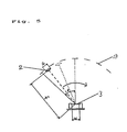
- the measurement of temperature of an object can be conducted over a whole measurement area without leaving any area in which the measurement is impossible by satisfying the following condition : wherein, a(mm) is an effective radius of lens in the direction of cicumference, f(mm) is a forcal length of the lens, w(mm) is an effective width of an infrared sensor in the direction of scanning and ⁇ (deg) is an angle between an utmost end of the measuring area and the center of the measuring area.
- the measurement of temperature of an object can be conducted without optical choper by intermitting infrared ray with use of combination of a movable slit unit rotating together with the lens and a stational slit unit arranged adjacent to the movable slit unit.
- incident infrared ray 1 is collected through lenses 2a, 2b on an array sensor 3 comprising a plurarity of pyro-electric type infrared sensor elements arranged in one direction.
- the array sensor 3 is attached to a setting plate 301 fixed to a stationary base plate 302.
- the lenses 2a and 2b are arranged on outer surface of a cylinder 4 which is rotated about a rotation axis arranged parallel to the direction of arrangement of the sensor elements of array sensor 3.
- each of pixels of array sensor 3 is constituted with a face electrode 8 and back electrode 9 arranged on the both surfaces of pyro-electric material plate 7 and the electromotive force generated in each pixel is processed in an inpedance converter 10 and then processed in a signal processor to obtain information relating to the position or temperature of the object, which is a heat source.
- the optical system and mechanical system occupy only a volume of a cylinder 4 having a diameter equal to the focal length of the lenses 2a, 2b and a rotation driving means. Therefore, the invention gives an apparatus of simpler structure and smaller in size as compared with the conventional system which uses point sensor and scanning type reflecting mirror. Further, even if a lens having narrow view is used as the lenses 2a, 2b, the apparatus of the invention affords enough wide view in the direction of rotation.
- the lenses 2a and 2b are arranged respectively on the front and back sides of the cylinder 4 and the angle of setting thereof in the direction of rotation axis is adjusted so that the lens 2a has an upward view and the lens 2b has downward view, whereby the view is divided into separated half fields while the cylinder 4 turns one round.
- each of the lenses is allowed to have a half angle of view and the array sensor is permitted to have a half number of pyroelectric elements.
- the apparatus has an array sensor of three pixels and two lenses 2a and 2b, and the view is divided into six areas.
- the apparatus will have a view angle of 6 0°if an area has a view of 1 0°. More improved effect will be obtained, if the number of lenses is increased and the view angle is divided into more than two.
- Example 2 which overcomes this problem will be described referring to the drawings.
- Fig.2a shows constitution of a pixel of array sensor 3 of the example wherein one pixel is composed of a plularity of pyroelectric elements 12 which are connected with electrodes 8, 9 on the both sides thereof.
- the constitution differs from that of Fig.1b in which one pixel is composed of one pyroelectric element.
- the pyroelectric elements are arranged in two rows of 12a side and 12b side.
- pyroelectric elements arranged adjacent to each other in the direction of X are connected with a back electrode 9 such as 12a and 12b, and pyroelectric elements arranged adjacent to pyroelectric elements in the direction of direction of Y, the latter being connected with a back electrode, namely pyroelectric elements arranged in the diagonal direction, such as 12a and 12c, are connected with a front electrode 8 and all pyroelectric elements are connected in series. As shown in the drawing.
- the polarity of all of the pyroelectric elements of 12b side becomes positive and the polarity of all of the pyroelectric elments of 12a side becomes negative.
- the other pixels of array sensor 3 are arranged in the Y direction and the image of infrared ray collected by the lens 2 is scanned in the X direction by rotation of the lens 2.
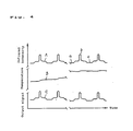
- A shows a wave form of infrared ray coming into a pixel by scanning of lens 2
- a is an image of the object having a width larger than that of the pixel
- b corresponds to an image of an object having a width similar to that of pyro-electric element 12a.
- B is a wave form of an output signal when one pyroelectric element is composed of one pixel, wherein, the temperature of the pyroelectric element is raised when it receives infrared ray from the object to raise the output voltage, so that the position of the object is detected by the change of the voltage.
- a large change of voltage such as c
- d minor changeof voltage
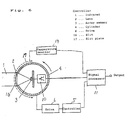
- the constitution of the apparatus of this example is different from that of Fig. 1 in that a screening plate 13, which limits the view of array sensor 3, is provided at a position nearby the lens 2 within an area of scanning view of the lens 2, and the temperature of the screening plate 13 is measured by a temperature monitoring part 14 to determine a standard temperature.
- Information of temperature of an object can be obtained without a chopper by observing alternativeately the screening plate and the object while controlling rotation of lens 2 via a controller 5.
- the output from a pyroelectric type infrared sensor is obtained as an integrated type corresponding to the incident infrared energy, in a period shorter than the temperature time constant, and, therefore, a relative distribution of infrared intensity is obtained by using a signal processor of differentiation type.
- a signal processor of differentiation type it is difficult to obtain the distribution of infrared intensity exactly for a long period of time since the generated output is attenuated after lapse of time of the temperature time constant due to thermal diffusion from the pyroeiectric element.
- the wave form of the output signal C takes the same form as that of distrinut:on of incident infrared ray.
- the temperature distribution of an object can be obtained by making the output voltage of state a as a standard at every one cycle, since, as above mentioned, the output voltage of state a wherein only the infrared ray comes only from the screening plate is not always constant at every cycle. With this system, it is possible to obtain the information of temperature distribution without changing the constitution of the apparatus and prepare a compact apparatus.
- Fig. 5 shows a top illustration view wherein, a is an effective diameter of the lens in the direction of scanning, f is a focal length of the lens , w is an effective width of the pyroelectric sensor in the scanning direction and ⁇ is an angle formed between an utmost end of the whole measuring area and the center of the whole measuring area.
- Example 5 of the invention will be described below with reference to the drawings.
- This example differs from that of Fig.3 in that a plurarity of elongated slits 16 are provided at the outer periphery of cylinder 4 along the rotation axis thereof in the direction of the circonference at constant intervals, said slits being rotated with the cylinder, and a slit plate 17 provided with a plurarity of slits at the same intervals as the slits 16 on a circle concetrically with the cylinder but slightly outer side thereof.
- the intensity of infrared ray 1 is determined by rotating the slits 16 together with the cylinder 4 and keeping the slit plate 17 stationary to intermit the incident infrered ray thereby measuring the amplitude of output alternating signal.
- This method affords a significantly simple structure which is capable of conducting scanning along the optical axis and intermitting of infrared ray with a single driving mechanism.
- the slits 16 and slit plate 17 may be provided within a cylinder having a diameter equal to the focal length of the lens or on the outer periphery thereof, and therefore, the constitution affords capability of intermitting infrared ray without losing the advantage that the apparatus is compact in size.
- the slits 17, which is provided on the outer periphery of the cylinder 4, may be provided in the inner side thereof.
Landscapes
- Engineering & Computer Science (AREA)
- Power Engineering (AREA)
- Physics & Mathematics (AREA)
- General Physics & Mathematics (AREA)
- Spectroscopy & Molecular Physics (AREA)
- Radiation Pyrometers (AREA)
- Photometry And Measurement Of Optical Pulse Characteristics (AREA)
Applications Claiming Priority (4)
| Application Number | Priority Date | Filing Date | Title |
|---|---|---|---|
| JP151952/90 | 1990-06-11 | ||
| JP2151952A JP2523948B2 (ja) | 1990-06-11 | 1990-06-11 | 焦電型赤外線検知装置 |
| JP2151957A JPH0443929A (ja) | 1990-06-11 | 1990-06-11 | 走査型非接触温度測定装置およびそれを用いた空調装置 |
| JP151957/90 | 1990-06-11 |
Publications (3)
| Publication Number | Publication Date |
|---|---|
| EP0461837A2 true EP0461837A2 (fr) | 1991-12-18 |
| EP0461837A3 EP0461837A3 (en) | 1992-09-16 |
| EP0461837B1 EP0461837B1 (fr) | 1995-08-16 |
Family
ID=26481015
Family Applications (1)
| Application Number | Title | Priority Date | Filing Date |
|---|---|---|---|
| EP91305213A Expired - Lifetime EP0461837B1 (fr) | 1990-06-11 | 1991-06-10 | Détecteur infrarouge pyroélectrique |
Country Status (3)
| Country | Link |
|---|---|
| US (1) | US5281818A (fr) |
| EP (1) | EP0461837B1 (fr) |
| DE (1) | DE69112136T2 (fr) |
Cited By (6)
| Publication number | Priority date | Publication date | Assignee | Title |
|---|---|---|---|---|
| EP0582941A1 (fr) * | 1992-08-03 | 1994-02-16 | Matsushita Electronics Corporation, Ltd. | Appareil pour la mesure de la distribution de la température |
| US5660471A (en) * | 1993-02-26 | 1997-08-26 | Matsushita Electric Industrial Co., Ltd. | Temperature distribution measuring device and measuring method |
| US7604399B2 (en) * | 2007-05-31 | 2009-10-20 | Siemens Energy, Inc. | Temperature monitor for bus structure flex connector |
| CN101886952A (zh) * | 2010-07-21 | 2010-11-17 | 淮南润成科技有限公司 | 矿用被动式热释电红外传感器 |
| CN102183795A (zh) * | 2011-02-28 | 2011-09-14 | 中北大学 | 基于动态下使用热释电红外传感器的目标探测系统及其方法 |
| CN102692277A (zh) * | 2011-03-25 | 2012-09-26 | 柯尼卡美能达商用科技株式会社 | 人检测装置和包括该人检测装置的图像形成装置 |
Families Citing this family (8)
| Publication number | Priority date | Publication date | Assignee | Title |
|---|---|---|---|---|
| KR0133244Y1 (ko) * | 1994-11-11 | 1999-01-15 | 이형도 | 무방향성 초전형 센서 |
| DE19753884A1 (de) * | 1997-12-05 | 1999-06-10 | Behr Gmbh & Co | Sensor zur Erfassung der Sonneneinstrahlung |
| US6252506B1 (en) * | 1999-09-22 | 2001-06-26 | Yuan-Tai Hsieh | Device for finding a position of a human |
| CN100465594C (zh) * | 2006-03-23 | 2009-03-04 | 上海理工大学 | 紫外增强型电学定标热释电辐射计 |
| MY182329A (en) * | 2013-05-17 | 2021-01-19 | Panasonic Ip Corp America | Thermal image sensor and user interface |
| CN105865636B (zh) * | 2015-02-06 | 2022-01-11 | 松下知识产权经营株式会社 | 红外线检测装置 |
| CN109682500B (zh) * | 2018-12-29 | 2023-11-14 | 山东磐然仪器集团有限公司 | 一种温度计量装置检定用扫描开关及检定系统和方法 |
| CN215583397U (zh) * | 2021-07-06 | 2022-01-21 | 永艺家具股份有限公司 | 一种具有智能调整功能的升降桌 |
Family Cites Families (8)
| Publication number | Priority date | Publication date | Assignee | Title |
|---|---|---|---|---|
| FR2326715A1 (fr) * | 1975-10-01 | 1977-04-29 | France Etat | Viseur panoramique pour visee diurne et nocturne |
| JPS5933207B2 (ja) * | 1976-09-27 | 1984-08-14 | 株式会社千野製作所 | 一軸走査型放射温度計 |
| JPS58180918A (ja) * | 1982-04-16 | 1983-10-22 | Mitsubishi Electric Corp | 赤外線監視装置 |
| US4665430A (en) * | 1984-01-20 | 1987-05-12 | Matsushita Electric Industrial Co., Ltd | Monitoring apparatus |
| DE3615946A1 (de) * | 1986-05-12 | 1987-11-19 | Siemens Ag | Raumzustandssensor |
| GB8803623D0 (en) * | 1988-02-17 | 1988-03-16 | Atomic Energy Authority Uk | Scanning system |
| US4930864A (en) * | 1988-08-02 | 1990-06-05 | Eltec Instruments, Inc. | Domed segmented lens systems |
| US5159200A (en) * | 1991-04-12 | 1992-10-27 | Walter Kidde Aerospace Inc. | Detector for sensing hot spots and fires in a region |
-
1991
- 1991-06-10 US US07/712,681 patent/US5281818A/en not_active Expired - Fee Related
- 1991-06-10 EP EP91305213A patent/EP0461837B1/fr not_active Expired - Lifetime
- 1991-06-10 DE DE69112136T patent/DE69112136T2/de not_active Expired - Fee Related
Cited By (10)
| Publication number | Priority date | Publication date | Assignee | Title |
|---|---|---|---|---|
| EP0582941A1 (fr) * | 1992-08-03 | 1994-02-16 | Matsushita Electronics Corporation, Ltd. | Appareil pour la mesure de la distribution de la température |
| US5567052A (en) * | 1992-08-03 | 1996-10-22 | Matsushita Electric Industrial Co., Ltd. | Temperature distribution measurement apparatus |
| US5660471A (en) * | 1993-02-26 | 1997-08-26 | Matsushita Electric Industrial Co., Ltd. | Temperature distribution measuring device and measuring method |
| US7604399B2 (en) * | 2007-05-31 | 2009-10-20 | Siemens Energy, Inc. | Temperature monitor for bus structure flex connector |
| CN101680931B (zh) * | 2007-05-31 | 2013-03-27 | 西门子能源公司 | 用于总线结构挠性连接器的温度监视器 |
| CN101886952A (zh) * | 2010-07-21 | 2010-11-17 | 淮南润成科技有限公司 | 矿用被动式热释电红外传感器 |
| CN102183795A (zh) * | 2011-02-28 | 2011-09-14 | 中北大学 | 基于动态下使用热释电红外传感器的目标探测系统及其方法 |
| CN102183795B (zh) * | 2011-02-28 | 2013-12-25 | 中北大学 | 基于动态下使用热释电红外传感器的目标探测系统及其方法 |
| CN102692277A (zh) * | 2011-03-25 | 2012-09-26 | 柯尼卡美能达商用科技株式会社 | 人检测装置和包括该人检测装置的图像形成装置 |
| CN102692277B (zh) * | 2011-03-25 | 2015-01-14 | 柯尼卡美能达商用科技株式会社 | 人检测装置和包括该人检测装置的图像形成装置 |
Also Published As
| Publication number | Publication date |
|---|---|
| EP0461837A3 (en) | 1992-09-16 |
| EP0461837B1 (fr) | 1995-08-16 |
| US5281818A (en) | 1994-01-25 |
| DE69112136D1 (de) | 1995-09-21 |
| DE69112136T2 (de) | 1996-04-04 |
Similar Documents
| Publication | Publication Date | Title |
|---|---|---|
| EP0461837A2 (fr) | Détecteur infrarouge pyroélectrique | |
| CA1170742A (fr) | Pyrometre a balayage electronique | |
| EP1774772B1 (fr) | Dispositif d'imagerie a balayage | |
| US4365307A (en) | Temperature pattern measuring device | |
| WO1993016353A1 (fr) | Procede et dispositif servant a mesurer la forme de la surface d'un objet | |
| GB2116315A (en) | Ash fusion analyzer | |
| JP3293350B2 (ja) | 人体検知装置 | |
| US3398285A (en) | Spectro-radiometer with means for eliminating background noise | |
| JP2006177848A (ja) | 温度分布検出装置 | |
| US3508068A (en) | Optical strip mapping system | |
| JP2523948B2 (ja) | 焦電型赤外線検知装置 | |
| JPH07101120B2 (ja) | 空調装置 | |
| EP0410745B1 (fr) | Interrupteur périodique à réflecteur pour les systèmes d'imagerie infrarouge | |
| US4316088A (en) | Process and device for measuring by infrared thermometry the temperature of a wire, bar or tube, or a metal | |
| JPH02197747A (ja) | 空気調和機 | |
| JPH0862049A (ja) | 熱画像検出装置 | |
| JPH0875545A (ja) | 焦電型赤外線検出装置 | |
| JPH0886884A (ja) | 熱物体検出装置 | |
| JPH07301568A (ja) | 赤外線検知装置 | |
| JPH0979967A (ja) | 流体中の浮遊粒子計測方法及びその装置 | |
| JPH0543363Y2 (fr) | ||
| JPH08152483A (ja) | 人体検知器 | |
| JP3422619B2 (ja) | 焦電型赤外線センサ及び装置 | |
| JP2552270B2 (ja) | 人数検出装置 | |
| JPS63134990A (ja) | 人数検出装置 |
Legal Events
| Date | Code | Title | Description |
|---|---|---|---|
| PUAI | Public reference made under article 153(3) epc to a published international application that has entered the european phase |
Free format text: ORIGINAL CODE: 0009012 |
|
| AK | Designated contracting states |
Kind code of ref document: A2 Designated state(s): DE FR GB NL |
|
| PUAL | Search report despatched |
Free format text: ORIGINAL CODE: 0009013 |
|
| AK | Designated contracting states |
Kind code of ref document: A3 Designated state(s): DE FR GB NL |
|
| 17P | Request for examination filed |
Effective date: 19930308 |
|
| 17Q | First examination report despatched |
Effective date: 19940407 |
|
| GRAA | (expected) grant |
Free format text: ORIGINAL CODE: 0009210 |
|
| AK | Designated contracting states |
Kind code of ref document: B1 Designated state(s): DE FR GB NL |
|
| PG25 | Lapsed in a contracting state [announced via postgrant information from national office to epo] |
Ref country code: NL Free format text: LAPSE BECAUSE OF FAILURE TO SUBMIT A TRANSLATION OF THE DESCRIPTION OR TO PAY THE FEE WITHIN THE PRESCRIBED TIME-LIMIT Effective date: 19950816 |
|
| REF | Corresponds to: |
Ref document number: 69112136 Country of ref document: DE Date of ref document: 19950921 |
|
| ET | Fr: translation filed | ||
| NLV1 | Nl: lapsed or annulled due to failure to fulfill the requirements of art. 29p and 29m of the patents act | ||
| PLBE | No opposition filed within time limit |
Free format text: ORIGINAL CODE: 0009261 |
|
| STAA | Information on the status of an ep patent application or granted ep patent |
Free format text: STATUS: NO OPPOSITION FILED WITHIN TIME LIMIT |
|
| 26N | No opposition filed | ||
| REG | Reference to a national code |
Ref country code: GB Ref legal event code: IF02 |
|
| PGFP | Annual fee paid to national office [announced via postgrant information from national office to epo] |
Ref country code: FR Payment date: 20040608 Year of fee payment: 14 |
|
| PGFP | Annual fee paid to national office [announced via postgrant information from national office to epo] |
Ref country code: GB Payment date: 20040609 Year of fee payment: 14 |
|
| PGFP | Annual fee paid to national office [announced via postgrant information from national office to epo] |
Ref country code: DE Payment date: 20040617 Year of fee payment: 14 |
|
| PG25 | Lapsed in a contracting state [announced via postgrant information from national office to epo] |
Ref country code: GB Free format text: LAPSE BECAUSE OF NON-PAYMENT OF DUE FEES Effective date: 20050610 |
|
| PG25 | Lapsed in a contracting state [announced via postgrant information from national office to epo] |
Ref country code: DE Free format text: LAPSE BECAUSE OF NON-PAYMENT OF DUE FEES Effective date: 20060103 |
|
| PG25 | Lapsed in a contracting state [announced via postgrant information from national office to epo] |
Ref country code: FR Free format text: LAPSE BECAUSE OF NON-PAYMENT OF DUE FEES Effective date: 20060228 |
|
| GBPC | Gb: european patent ceased through non-payment of renewal fee |
Effective date: 20050610 |
|
| REG | Reference to a national code |
Ref country code: FR Ref legal event code: ST Effective date: 20060228 |