EP0461841A2 - Connecteur électrique à jack blindé - Google Patents
Connecteur électrique à jack blindé Download PDFInfo
- Publication number
- EP0461841A2 EP0461841A2 EP91305219A EP91305219A EP0461841A2 EP 0461841 A2 EP0461841 A2 EP 0461841A2 EP 91305219 A EP91305219 A EP 91305219A EP 91305219 A EP91305219 A EP 91305219A EP 0461841 A2 EP0461841 A2 EP 0461841A2
- Authority
- EP
- European Patent Office
- Prior art keywords
- insulator
- shield
- cavity
- jack connector
- shielded electrical
- Prior art date
- Legal status (The legal status is an assumption and is not a legal conclusion. Google has not performed a legal analysis and makes no representation as to the accuracy of the status listed.)
- Withdrawn
Links
Images




Classifications
-
- H—ELECTRICITY
- H01—ELECTRIC ELEMENTS
- H01R—ELECTRICALLY-CONDUCTIVE CONNECTIONS; STRUCTURAL ASSOCIATIONS OF A PLURALITY OF MUTUALLY-INSULATED ELECTRICAL CONNECTING ELEMENTS; COUPLING DEVICES; CURRENT COLLECTORS
- H01R13/00—Details of coupling devices of the kinds covered by groups H01R12/70 or H01R24/00 - H01R33/00
- H01R13/648—Protective earth or shield arrangements on coupling devices, e.g. anti-static shielding
- H01R13/658—High frequency shielding arrangements, e.g. against EMI [Electro-Magnetic Interference] or EMP [Electro-Magnetic Pulse]
- H01R13/6581—Shield structure
- H01R13/6582—Shield structure with resilient means for engaging mating connector
-
- H—ELECTRICITY
- H01—ELECTRIC ELEMENTS
- H01R—ELECTRICALLY-CONDUCTIVE CONNECTIONS; STRUCTURAL ASSOCIATIONS OF A PLURALITY OF MUTUALLY-INSULATED ELECTRICAL CONNECTING ELEMENTS; COUPLING DEVICES; CURRENT COLLECTORS
- H01R2201/00—Connectors or connections adapted for particular applications
- H01R2201/16—Connectors or connections adapted for particular applications for telephony
-
- H—ELECTRICITY
- H01—ELECTRIC ELEMENTS
- H01R—ELECTRICALLY-CONDUCTIVE CONNECTIONS; STRUCTURAL ASSOCIATIONS OF A PLURALITY OF MUTUALLY-INSULATED ELECTRICAL CONNECTING ELEMENTS; COUPLING DEVICES; CURRENT COLLECTORS
- H01R24/00—Two-part coupling devices, or either of their cooperating parts, characterised by their overall structure
- H01R24/60—Contacts spaced along planar side wall transverse to longitudinal axis of engagement
- H01R24/62—Sliding engagements with one side only, e.g. modular jack coupling devices
Definitions
- the present invention relates to a shielded electrical connector and more particularly to a modular jack connector for use in the interconnection of peripheral computer equipment to a computer.
- peripheral equipment In the modern office environment, various pieces of peripheral equipment, for example, printers or plotter devices are commonly interconnected to a main computer. Most computer input/output (I/O) connection interfaces are standard plug or socket RS 232 connectors. While some of the peripheral devices include cables terminated with compatible RS 232 connectors for mateable interconnection with the connector on the computer, it is not uncommon for the peripheral equipment to have a cable assembly terminated with connectors other than the standard RS 232. For example, peripheral devices may be terminated with telephone jacks or plugs.
- an adapter When interconnecting a peripheral piece of equipment that is terminated with other than the standard RS 232 type connector, an adapter must be used to interconnect the two different types of connector configurations.
- present known adapters are used to interconnect commercial telephone connectors to the standard RS 232 interfaces on a computer. It is also known that certain manufacturers of peripheral equipment terminate cables from the equipment with customized telephone connectors. With an adapter specifically configured to interconnect to the customized telephone connector, the manufacturers of the peripheral equipment may exercise a certain degree of control over which computers the peripheral equipment can be connected. Further, by interconnecting in the adapter the contacts of the customized telephone jack to selective pins of the commonly used 25 position RS 232 device, a further degree of control of the ability to connect peripheral equipment to computers may be exercised.
- EMI electro magnetic interference
- a shielded electrical jack connector comprising: an insulator defining a cavity therewithin, said insulator including an exterior surface having an aperture formed therethrough, said aperture communicating with said cavity and defining a receptacle for receipt of a plug connector, said insulator including resilient latch means and a base which includes said exterior surface through which said aperture is formed, and a pair of spaced, opposing sidewalls upstanding from said base; a plurality of electrical contacts supported by said insulator and extending into said cavity, said contacts each terminating in a projecting conductor; an electrically conductive ground contact supported by said insulator, said ground contact comprising a terminal extending into said cavity for engagement with a plug connector upon receipt thereof into said receptacle and a friction surface projecting therefrom, said ground contact including a pair of opposed legs and a connecting portion, each leg being supported by a respective different one of said opposing sidewalls; and an electrically conductive shield supported on said insulator, said shield
- a modular jack insert preferably supports the electrical contacts that are terminated with insulated conductors.
- the insulator is preferably formed to have a chamber communicating with the cavity, the insert being received in the chamber, the insulator having resilient means for releasably retaining the insert therewithin.
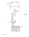
- Figure 1 is an exploded side elevation view showing the components of a preferred form of the shielded electrical connector jack connector of the present invention.
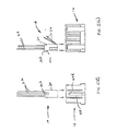
- Figure 2(a) and Figure 2(b) are side elevation and end elevation views, respectively, of a commercially available modular jack insert used as one of the elements of the preferred form of the connector of Figure 1.
- Figure 3 is a top perspective view of the insulator and ground contact of the jack connector of Figure 1 and an inverted view of the shield of the jack connector of Figure 1 partially broken away to show interior details thereof.
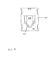
- Figure 4 is a bottom plan view of the insulator of the connector jack of Figure 1.
- Figures 5 (a) through 5 (f) illustrate the sequence of assembly of the preferred jack connector of Figure 1.
- Figure 5 (a) is an exploded side elevation view of the insulator and insert of the connector of Figure 1.
- Figure 5 (b) is an end view of the view shown in Figure 4 (a).
- Figure 5 (c) is an exploded side elevation view of the assembly of Figure 5 (a) and the ground contact.
- Figure 5 (d) is an exploded sectional view of the view of Figure 5 (c) as seen along viewing lines IV-IV, showing the ground contact before and after assembly to the insulator.
- Figure 5 (e) is an exploded side elevation view of the assembly of Figure 5 (c) and the shield, the shield being partially sectioned to show inner details thereof.
- Figure 5 (f) is an end elevation view of the view of Figure 5 (e).
- Figure 6 is a side elevation view of the complete assembly of the jack connector of Figure 1.
- Figure 7 is a bottom plan view of the complete connector of Figure 6.
- Jack connector 10 basically comprises an insulator 12, a modular jack insert 14, a ground contact 16 and a cover shield 18.
- jack connector 10 is particularly useful in an adapter that permits interconnection between a peripheral device and a computer which have differently configured input/output connectors.
- Insert 14 comprises an insulative body 20, preferably of thermoplastic material, supporting a plurality of electrical contacts 22 that are individually terminated to a respective insulated conductor 24.
- Electrical contacts 22 are formed of electrically conductive material, such as a copper alloy, and are supported by the insulative insert body 20 in exposed, cantilevered, deflectable fashion. In the preferred insert, there are four electrical contacts 22 and terminated conductors 24 projecting outwardly from the insert body 20, it being understood that other numbers of contacts and conductors may be used.
- Insert body 20 includes a projecting locking member 26 having an inclined surface 26a and a generally flat locking surface 26b. A recess 28 is formed into and partially along one of the sides of the insulative body 20.
- the insulator 12 preferably formed of an insulative material such as glass-filled polyester, is configured in a generally rectangular block form having a base 30, a pair of spaced opposing sidewalls 32 upstanding from base 30 and a pair of spaced opposing endwalls 34 projecting upwardly from base 30.
- a generally centrally located cavity 36 extends into the insulator 12 between the sidewalls 32 and the endwalls 34.
- Formed in each of the sidewalls 32 is a recessed track 32a for guided receipt of the ground contact 16.
- an opening 32b Adjacent the base 30 in each of the sidewalls 32 is a pocket 38 defined by an outer wall portion 32c and an inner wall portion 32d of each of the sidewalls 32 as seen further with reference to Figure 5 (d).
- each of the sidewalls 32 preferably adjacent the endwalls 34, there are formed resiliently deflectable latching members 40.
- Each of the latching members 40 upstands from insulator base 30 in a cantilevered manner and terminates at its free distal end in a generally flat, protruding latching ledge 40a.
- a chamber 42 Formed in communication with the insulator cavity 36 and preferably disposed adjacent to and in communication with one of the endwalls 34, is a chamber 42.
- Chamber 42 is particularly configured to receive in resilient, retentive fashion the insulative body 20 of the jack insert 14.
- the endwall 34 adjacent the chamber 42 comprises a resilient latch 44 for releasably retaining the insert 14 in the chamber 42.
- Latch 44 upstands from the insulator base 30 in cantilevered manner and comprises a frame defined by two vertically projecting and transversely spaced elements 44a defining a slot 44b therebetween, elements 44a being connected at the free distal ends by a connecting element 44c.
- the lower edge 44d of connecting element 44c defines a cooperative latching structure for resiliently engaging the locking surface 26b of the locking member 26 of the jack insert 14.
- the base 30 of the insulator 12 has an exterior surface 30a through which an aperture 30b is formed in communication with the insulator cavity 36.
- the aperture 30b defines a receptacle and is adapted to receive therein a complementary, mateable plug connector for engagement with the contacts 22 of the jack insert, as will be described hereinafter.
- One edge of the walls defining the aperture 30b is particularly configured to have a key-way 30c of size and shape to only receive a plug connector having like size and shape. As such, the type of connector which may be received in aperture 30b may be controlled.
- the ground contact 16 is formed of an electrically conductive material, such as a copper - nickel - tin alloy, and is preferably formed from a stamped, generally flat sheet.
- Contact 16 comprises a pair of spaced opposing legs 16a and a connecting portion 16b. As illustrated, the contact is in a generally inverted U-shape configuration. Formed in each of the legs 16a is a recess or dimple punched into each of the legs 16a and defining an outwardly projecting, raised bump 16c of generally semi-hemispherical configuration. Raised bumps 16c provide a friction surface for engagement with the shield 18 as will be set forth subsequently.
- each of the legs 16a there is provided a reversely bent portion 16d interconnected by a curved bight 16e.
- the reversely bent portions 16d are bent inwardly towards each other and each respectively terminate in a terminal 16f.
- the terminals 16f are each configured to be received in a respective sidewall opening 32b and to extend into the insulator cavity 36c, as depicted in Figure 5 (d).
- the depending legs 16a of the ground contact 16 are formed to have a slightly outward configuration to provide a biased, frictional receipt in the insulator 12 as will be described.
- Shield 18 comprises a cover surface 18a from which depend opposing, spaced side surfaces 18b and opposing, spaced end surfaces 18c.
- an opening 18d located to be in registry with the insulator chamber 42 upon receipt of the shield onto the insulator 12.
- An edge surface 18f of each hole 18e serves as a latching surface for releasable, retentive engagement with the latching ledges 40a on the latching members 40.
- a raised block 18g Adjacent each of the holes 18e, there is provided a raised block 18g which forms a barrier for minimizing subsequent flow of a potting compound into the interior of the shield.
- a wall 18h is provided adjacent the opening 18d, which wall 18h also serves as a further support for the insert 14 upon assembly.
- An interior wall surface 18i on each of the side surfaces 18b is adapted to be engaged with the raised bumps 16c on the ground contact, such that the ground contact 16 and the shield 18 are provided in electrically common potential.
- the shield is formed of electrically conductive material and is preferably of a zinc alloy.
- Figures 5 (a) through 5 (f) illustrate the assembly sequence of the jack connector 10.
- Figures 5 (a) and 5 (b) illustrate the assembly of the modular jack insert 14 to the jack connector insulator 12.
- the insert body 20 is received in the insulator chamber 42, with the locking member 26 resiliently received by the insulator latch 44, the locking surface 26b being in cooperative engagement with the lower edge 44d upon receipt of the body 20 in the chamber 42.
- the inclined surface 26a outwardly deflects the latch 44 until the lower edge 44d engages the locking surface 26b.
- the contacts 22 extend in cantilevered fashion into the insulator cavity 36, the insulated conductors 24 projecting upwardly from the upper surface of the insulator 12.
- FIGs 5 (c) and 5 (d) the attachment of the ground contact 16 to the connector insulator 12 is illustrated.
- the outwardly disposed legs are urged inwardly to create a bias and the legs 16a are received in the recessed tracks 32a on the insulator sidewalls 32.
- the bight 16e of each of the legs 16a is seated in a respective pocket 38 formed at the base of each of the sidewalls 32, as illustrated in Figure 5 (d).
- the contact is frictionally retained as a result of the bias of the contact 16, and the terminals 16f project through the sidewall openings 32b and into the insulator cavity 36.
- the connecting portion 16b of the ground contact 16 traverses the insulator cavity 36 spanning the sidewalls 32 of the insulator 12 upon assembly thereto.
- FIGs 6 and 7 The completed assembly of the jack connector 10 is illustrated in Figures 6 and 7.
- the side surfaces 18b and the end surfaces 18c of the shield 18 extend nearly fully along the sidewalls 32 and endwalls 34 respectively of the insulator 12.
- the contacts 22 are disposed for access to contacts of a complementary plug through the particularly configured aperture 30b formed through the base of the insulator 12.
- a plug connector may be a customized telephone connector having its housing configured to be received in the key 36c formed in the insulator base.
- the jack connector 10 of the subject invention has particular utility in an interconnection adapter which includes the jack connector 10 (having one configuration) and another connector (not shown), such as a standard RS 232 connector (having a different configuration).
- a peripheral device terminated by a connector of one configuration can be connected to a computer having a connector of different configuration.
- the insulated conductors 24 may also be selectively wired to pins (plug or socket) of the other connector having the different from the configuration.
- the standard RS 232 connector usually has more than four contacts and typically has twenty-five contacts. Accordingly, by selectively wiring four pins of an RS 232 connector to the four conductors of the jack connector 10, further control of the inter-connection capabilities of an adapter can be achieved.
Landscapes
- Details Of Connecting Devices For Male And Female Coupling (AREA)
Applications Claiming Priority (2)
| Application Number | Priority Date | Filing Date | Title |
|---|---|---|---|
| US536811 | 1990-06-12 | ||
| US07/536,811 US5064387A (en) | 1990-06-12 | 1990-06-12 | Shielded electrical jack connector |
Publications (2)
| Publication Number | Publication Date |
|---|---|
| EP0461841A2 true EP0461841A2 (fr) | 1991-12-18 |
| EP0461841A3 EP0461841A3 (en) | 1992-06-03 |
Family
ID=24140020
Family Applications (1)
| Application Number | Title | Priority Date | Filing Date |
|---|---|---|---|
| EP19910305219 Withdrawn EP0461841A3 (en) | 1990-06-12 | 1991-06-10 | Shielded electrical jack connector |
Country Status (4)
| Country | Link |
|---|---|
| US (1) | US5064387A (fr) |
| EP (1) | EP0461841A3 (fr) |
| JP (1) | JPH04233022A (fr) |
| CA (1) | CA2044433A1 (fr) |
Families Citing this family (25)
| Publication number | Priority date | Publication date | Assignee | Title |
|---|---|---|---|---|
| US5326931A (en) * | 1991-11-21 | 1994-07-05 | The Whitaker Corporation | Cable distribution interface unit |
| US5431586A (en) * | 1993-12-21 | 1995-07-11 | Hubbell Incorporated | Electrical connector with modular nose |
| US6093059A (en) * | 1999-01-25 | 2000-07-25 | Thomas & Betts International, Inc. | Contact configuration in modular jack |
| US8862452B2 (en) * | 2001-02-14 | 2014-10-14 | Xio, Inc. | Control system simulator and simplified interconnection control system |
| US7216191B2 (en) * | 2001-02-14 | 2007-05-08 | Berkeley Process Control, Inc. | System for programmed control of signal input and output to and from cable conductors |
| US7822896B1 (en) | 2001-02-14 | 2010-10-26 | Berkeley Process Control, Inc. | Electronically configurable connector module |
| US20080218338A1 (en) * | 2007-03-07 | 2008-09-11 | Optimal Licensing Corporating | System and method for premises monitoring using weight detection |
| US20080218372A1 (en) * | 2007-03-07 | 2008-09-11 | Optimal Licensing Corporation | Light switch used as a communication device |
| US20080218307A1 (en) * | 2007-03-07 | 2008-09-11 | Optimal Licensing Corporation | Anticipatory utility control device |
| US20090027196A1 (en) * | 2007-03-07 | 2009-01-29 | Roland Schoettle | System and method for premises monitoring and control using self-learning detection devices |
| US7497273B2 (en) * | 2007-03-07 | 2009-03-03 | Optimal Innovations, Inc. | Plug and play utility control modules |
| US20080218319A1 (en) * | 2007-03-07 | 2008-09-11 | Optimal Licensing Corporation | Systems and methods for linking utility control devices |
| US20090044964A1 (en) * | 2007-08-16 | 2009-02-19 | Optimal Innovations Inc. | Utility Outlets as a Security System |
| US20090049466A1 (en) * | 2007-08-16 | 2009-02-19 | Optimal Innovations Inc. | Using Utility Outlets to Determine and Report Media-Based Activity |
| US20090045968A1 (en) * | 2007-08-16 | 2009-02-19 | Optimal Innovations Inc. | Utility Outlets Capable of Presenting Images |
| US20090101386A1 (en) * | 2007-10-19 | 2009-04-23 | Optimal Innovations Inc. | Size unconstrained faceplate display for use with infrastructure device |
| US20090102679A1 (en) * | 2007-10-19 | 2009-04-23 | Optimal Innovations Inc. | Infrastructure device with removable face plate for remote operation |
| US20090137163A1 (en) * | 2007-11-26 | 2009-05-28 | Optimal Innovations Inc. | Infrastructure device with modular replaceable sensors |
| US20090135006A1 (en) * | 2007-11-26 | 2009-05-28 | Optimal Innovations Inc. | Infrastructure device with modular remote sensors |
| US20090274087A1 (en) * | 2008-05-01 | 2009-11-05 | Optimal Innovations Inc. | Utility outlets as remote control repeaters |
| US20090274064A1 (en) * | 2008-05-01 | 2009-11-05 | Optimal Innovations Inc. | Light switch as a wireless hub |
| CN121965193A (zh) * | 2011-04-01 | 2026-05-01 | 捷利知产股份有限公司 | 双面电连接器 |
| JP5765114B2 (ja) | 2011-07-26 | 2015-08-19 | スズキ株式会社 | 車体フレーム |
| WO2015164538A1 (fr) | 2014-04-23 | 2015-10-29 | Tyco Electronics Corporation | Connecteur électrique à capuchon de protection et à bornes protégées |
| CA3167009A1 (fr) * | 2020-02-10 | 2021-08-19 | Itt Manufacturing Enterprises Llc | Ensemble connecteur multiple |
Family Cites Families (21)
| Publication number | Priority date | Publication date | Assignee | Title |
|---|---|---|---|---|
| US3680031A (en) * | 1971-04-30 | 1972-07-25 | Gen Electric | Grounding device for mounting strap |
| US3790858A (en) * | 1973-01-29 | 1974-02-05 | Itt | Electrical connector with component grounding plate |
| US4088384A (en) * | 1976-11-29 | 1978-05-09 | Northern Telecom Limited | Adaptor for plug-in telephones |
| US4296991A (en) * | 1978-09-08 | 1981-10-27 | Amp Incorporated | Electrical connector receptacle |
| US4438998A (en) * | 1982-03-05 | 1984-03-27 | Amp Incorporated | Modular plug-dial modular jack adaptor |
| US4516815A (en) * | 1982-06-07 | 1985-05-14 | Spectrum Control, Inc. | RF filter connector |
| US4457575A (en) * | 1982-09-21 | 1984-07-03 | Amp Incorporated | Electrical connector having improved shielding and keying systems |
| US4941848A (en) * | 1984-01-16 | 1990-07-17 | Stewart Stamping Corp. | Shielded plug jack connector |
| US4781623A (en) * | 1984-01-16 | 1988-11-01 | Stewart Stamping Corporation | Shielded plug and jack connector |
| US4641901A (en) * | 1984-01-16 | 1987-02-10 | Stewart Stamping Corp. | Printed circuit board jack for modular plug connector terminated cord |
| US4648665A (en) * | 1984-10-16 | 1987-03-10 | Amp Incorporated | Electronic key assemblies |
| US4602842A (en) * | 1984-12-03 | 1986-07-29 | Cts Corporation | Electrical connector receptacle |
| US4624515A (en) * | 1985-04-17 | 1986-11-25 | Thomas & Betts Corporation | Electrical connector with grounding clip |
| US4838811A (en) * | 1986-08-22 | 1989-06-13 | Hirose Electric Co., Ltd. | Modular connector with EMI countermeasure |
| US4695115A (en) * | 1986-08-29 | 1987-09-22 | Corcom, Inc. | Telephone connector with bypass capacitor |
| US4793059A (en) * | 1987-02-24 | 1988-12-27 | Pass & Seymour, Inc. | Automatic grounding clip |
| JPH0511667Y2 (fr) * | 1987-11-04 | 1993-03-23 | ||
| US4906203A (en) * | 1988-10-24 | 1990-03-06 | General Motors Corporation | Electrical connector with shorting clip |
| JPH0538547Y2 (fr) * | 1988-12-09 | 1993-09-29 | ||
| US4878858A (en) * | 1988-12-13 | 1989-11-07 | Molex Incorporated | Low profile shielded jack |
| CA2003124C (fr) * | 1989-11-17 | 1996-02-20 | Akira Hori | Borne de raccordement telephonique |
-
1990
- 1990-06-12 US US07/536,811 patent/US5064387A/en not_active Expired - Fee Related
-
1991
- 1991-06-10 EP EP19910305219 patent/EP0461841A3/en not_active Withdrawn
- 1991-06-12 JP JP3140400A patent/JPH04233022A/ja active Pending
- 1991-06-12 CA CA002044433A patent/CA2044433A1/fr not_active Abandoned
Also Published As
| Publication number | Publication date |
|---|---|
| EP0461841A3 (en) | 1992-06-03 |
| JPH04233022A (ja) | 1992-08-21 |
| CA2044433A1 (fr) | 1991-12-13 |
| US5064387A (en) | 1991-11-12 |
Similar Documents
| Publication | Publication Date | Title |
|---|---|---|
| US5064387A (en) | Shielded electrical jack connector | |
| US4602842A (en) | Electrical connector receptacle | |
| US6027375A (en) | Electrical connection device | |
| US4225209A (en) | Electrical connector receptacle | |
| US6139350A (en) | Latching system for a pin-and-socket connector | |
| EP0347097B1 (fr) | Système de connecteur électrique | |
| US4497526A (en) | Circuit board housing having self-contained modular jack | |
| US4392701A (en) | Tap connector assembly | |
| US4725249A (en) | Connector assembly | |
| EP0772898B1 (fr) | Enveloppe de protection de mise a la terre amelioree pour connecteurs electriques | |
| US4210376A (en) | Electrical connector receptacle | |
| US5697799A (en) | Board-mountable shielded electrical connector | |
| US6220898B1 (en) | Audio jack having means for reliably securing terminals thereof | |
| EP0658953A2 (fr) | Ensemble de douilles modulaires multiple | |
| US6095865A (en) | Modular jack | |
| US20050112952A1 (en) | Power jack connector | |
| US5695362A (en) | Hybrid grounded and stacked connector assembly with audio jacks | |
| WO1986003345A1 (fr) | Connecteur electrique | |
| US20030139091A1 (en) | Two part ganged mod jack assembly | |
| EP0624928A1 (fr) | Assemblage de connecteur électrique blindé | |
| US4717344A (en) | Connector for circuit boards | |
| US6095824A (en) | Electrical connector assembly | |
| US6190210B1 (en) | Low profile modular jack | |
| US6083041A (en) | Electrical connector mounting assembly | |
| EP0528228A1 (fr) | Dispositif à socle pour le logement des circuits intégrés |
Legal Events
| Date | Code | Title | Description |
|---|---|---|---|
| PUAI | Public reference made under article 153(3) epc to a published international application that has entered the european phase |
Free format text: ORIGINAL CODE: 0009012 |
|
| AK | Designated contracting states |
Kind code of ref document: A2 Designated state(s): BE CH DE ES FR GB IT LI LU NL SE |
|
| PUAL | Search report despatched |
Free format text: ORIGINAL CODE: 0009013 |
|
| AK | Designated contracting states |
Kind code of ref document: A3 Designated state(s): BE CH DE ES FR GB IT LI LU NL SE |
|
| 17P | Request for examination filed |
Effective date: 19921130 |
|
| 17Q | First examination report despatched |
Effective date: 19940201 |
|
| RAP3 | Party data changed (applicant data changed or rights of an application transferred) |
Owner name: THOMAS & BETTS CORPORATION |
|
| STAA | Information on the status of an ep patent application or granted ep patent |
Free format text: STATUS: THE APPLICATION IS DEEMED TO BE WITHDRAWN |
|
| 18D | Application deemed to be withdrawn |
Effective date: 19940812 |