EP0462057B1 - Schleifmaschine - Google Patents
Schleifmaschine Download PDFInfo
- Publication number
- EP0462057B1 EP0462057B1 EP91810412A EP91810412A EP0462057B1 EP 0462057 B1 EP0462057 B1 EP 0462057B1 EP 91810412 A EP91810412 A EP 91810412A EP 91810412 A EP91810412 A EP 91810412A EP 0462057 B1 EP0462057 B1 EP 0462057B1
- Authority
- EP
- European Patent Office
- Prior art keywords
- grinding wheel
- grinding
- axis
- column
- machine
- Prior art date
- Legal status (The legal status is an assumption and is not a legal conclusion. Google has not performed a legal analysis and makes no representation as to the accuracy of the status listed.)
- Revoked
Links
Images

Classifications
-
- B—PERFORMING OPERATIONS; TRANSPORTING
- B24—GRINDING; POLISHING
- B24B—MACHINES, DEVICES, OR PROCESSES FOR GRINDING OR POLISHING; DRESSING OR CONDITIONING OF ABRADING SURFACES; FEEDING OF GRINDING, POLISHING, OR LAPPING AGENTS
- B24B3/00—Sharpening cutting edges, e.g. of tools; Accessories therefor, e.g. for holding the tools
- B24B3/16—Sharpening cutting edges, e.g. of tools; Accessories therefor, e.g. for holding the tools of broaches
-
- B—PERFORMING OPERATIONS; TRANSPORTING
- B24—GRINDING; POLISHING
- B24B—MACHINES, DEVICES, OR PROCESSES FOR GRINDING OR POLISHING; DRESSING OR CONDITIONING OF ABRADING SURFACES; FEEDING OF GRINDING, POLISHING, OR LAPPING AGENTS
- B24B27/00—Other grinding machines or devices
- B24B27/0061—Other grinding machines or devices having several tools on a revolving tools box
-
- B—PERFORMING OPERATIONS; TRANSPORTING
- B24—GRINDING; POLISHING
- B24B—MACHINES, DEVICES, OR PROCESSES FOR GRINDING OR POLISHING; DRESSING OR CONDITIONING OF ABRADING SURFACES; FEEDING OF GRINDING, POLISHING, OR LAPPING AGENTS
- B24B3/00—Sharpening cutting edges, e.g. of tools; Accessories therefor, e.g. for holding the tools
Definitions
- the present invention relates to a numerically controlled machine for sharpening cutting tools comprising a table intended to support and maintain the cutting tool and a vertical column which can rotate around a vertical axis and carrying at least one grinding wheel head mounted on a turret fixed radially to the column, orientable about a horizontal axis and capable of moving vertically on the column, and electromechanical means for positioning the grinding wheel head around its horizontal axis.
- Such a machine is known from document US-A-4,524,544. It has also been marketed by the applicant under the brand HARO reference F4 CNC since 1984.
- the grinding wheel head is positioned around its horizontal axis by numerical control by means of a servomotor.
- machine tools are commonly used today comprising several tools each driven by a motor, these motors being controlled automatically by a computer.
- the machine would therefore include as many servomotors as grinding wheel heads.
- the present invention aims to simplify the construction and control of a numerically controlled sharpening machine equipped with several grinding wheel heads.
- the machine according to the invention is characterized in that it comprises at least one pair of diametrically opposed grinding wheel heads relative to the vertical axis of the column, integral in rotation about a common horizontal axis and orientable around this axis by a common electromechanical means.
- each grinding head had to be controlled by its own servo motor so that it could be controlled independently of another grinding head, it turns out that it is quite possible to order two grinding wheel heads using the same servomotor without prejudice to the performance of the machine, in particular the speed of work thereof. Indeed, when a grinding wheel has finished its work and must be replaced by another grinding wheel, the corresponding grinding wheel head must move half a turn around the vertical axis to come to occupy its working position. The time necessary for this movement is amply sufficient to proceed with the proper orientation of this grinding wheel head around its horizontal axis. As for the rotation of the grinding wheel head outside work around the common axis, it obviously does not matter.
- the invention becomes particularly interesting if the machine is equipped with four grinding wheel heads mounted in pairs on two common axes, each of these axes being controlled by a servomotor. This saves two servos, since you only need two servos instead of four. The machine is therefore simpler and the cost of its manufacture is reduced.
- Figure 1 is a simplified front view in elevation of a sharpening machine with four grinding wheel heads.
- Figure 2 is a side elevational view of this machine.
- Figure 3 is a plan view of this machine.
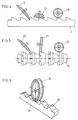
- Figure 4 shows the sharpening of a flat spindle using three different grinding wheels.
- Figure 5 shows the sharpening of a round spindle using three different grinding wheels.
- FIG. 6 illustrates the use of a fourth profiled wheel for sharpening a profiled flat spindle.
- FIGS 1 to 3 show a sharpening machine comprising a frame 1, a longitudinal slide 2 carrying a table 3 on which is fixed the sharpening tool, here a flat spindle 4.
- the machine further comprises a transverse slide 5 on which is mounted a vertical column 6 which can rotate about a vertical axis 7 and move vertically.
- On this column 6 are mounted four grinding wheel heads 8, 9, 10 and 11 orientable around a horizontal axis.
- Each grinding wheel head comprises a motor 12 driving a grinding wheel 13.
- Each grinding wheel head is mounted on a turret 14 fixed radially to the column 6.
- the grinding wheel heads 8 and 10 are diametrically opposite relative to the vertical axis 7 They are coaxial and mechanically secured to a common axis. The same applies to the grinding wheel heads 9 and 11.
- the mechanical axis of the grinding wheel heads 8 and 10 can be driven by a non-visible servomotor, in a manner known per se. The same applies to grinding wheel heads 9 and 11.
- the machine is controlled in a well known manner by numerical control by means of a control cabinet 15.
- the axes of the two pairs of grinding wheel heads have been shown to be coplanar, but they may very well be offset vertically with respect to each other.
- FIG. 4 represents the spindle 4 of FIGS. 1 to 3.
- the grinding wheel 16 of small thickness, comes to sharpen the face of the teeth of the spindle 4 by its conical surface.
- the grinding wheel 17 sharpens the skin of the teeth by its flat front face.
- the grinding wheel 18 is for example a chip breaking grinding wheel.
- FIG. 5 shows a part of a round spindle 19 also requiring three grinding wheels for its sharpening, namely a grinding wheel 20 for sharpening the face of the teeth, a grinding wheel 21 for sharpening the skin of the teeth and a grinding wheel 22 similar to grinding wheel 18.
- FIG. 6 partially represents a flat pin 23 whose teeth 24 have a particular profile requiring a grinding wheel 25 having the corresponding profile.
- This wheel 25 could be the fourth wheel of the machine illustrated in FIGS. 1 to 3.
Landscapes
- Engineering & Computer Science (AREA)
- Mechanical Engineering (AREA)
- Constituent Portions Of Griding Lathes, Driving, Sensing And Control (AREA)
- Finish Polishing, Edge Sharpening, And Grinding By Specific Grinding Devices (AREA)
Claims (2)
- Numerisch gesteuerte Schleifmaschine zum Schärfen von Schneidwerkzeugen, mit einem Tisch (3), der dazu bestimmt ist, das Schneidwerkzeug (4) zu tragen und in Position zu halten, mit einer vertikalen Säule (6), die um eine vertikale Achse (7) drehbar ist und wenigstens einen Schleifscheibenstock (8 bis 11) trägt, welcher auf einem Revolverkopf (14) montiert ist, der radial an der Säule (6) befestigt, um eine horizontale Achse orientierbar und vertikal an der Säule verschiebbar ist, und mit elektromechanischen Mitteln zum Orientieren des Schleifscheibenstocks um seine horizontale Achse, dadurch gekennzeichnet, dass sie wenigstens ein Paar von Schleifscheibenstöcken (8, 10) aufweist, die diametral bezüglich der vertikalen Achse (7) der Säule (6) gegenüberliegen, drehfest miteinander verbunden um eine gemeinsame horizontale Achse angeordnet und um diese Achse mit Hilfe eines gemeinsamen elektromechanischen Mittels orientierbar sind.
- Maschine nach Anspruch 1, dadurch gekennzeichnet, dass sie ein zweites Paar von Schleifscheibenstöcken (9, 11) aufweist, die diametral bezüglich der vertikalen Achse (7) der Säule (6) gegenüberliegen, fest an einer zweiten, quer zur ersten Achse verlaufenden Achse angebracht und um diese zweite Achse mit Hilfe eines zweiten gemeinsamen elektromechanischen Mittels orientierbar sind.
Applications Claiming Priority (2)
| Application Number | Priority Date | Filing Date | Title |
|---|---|---|---|
| CH1962/90A CH683330A5 (fr) | 1990-06-11 | 1990-06-11 | Machine à affûter. |
| CH1962/90 | 1990-06-11 |
Publications (2)
| Publication Number | Publication Date |
|---|---|
| EP0462057A1 EP0462057A1 (de) | 1991-12-18 |
| EP0462057B1 true EP0462057B1 (de) | 1993-12-15 |
Family
ID=4222676
Family Applications (1)
| Application Number | Title | Priority Date | Filing Date |
|---|---|---|---|
| EP91810412A Revoked EP0462057B1 (de) | 1990-06-11 | 1991-05-31 | Schleifmaschine |
Country Status (3)
| Country | Link |
|---|---|
| EP (1) | EP0462057B1 (de) |
| CH (1) | CH683330A5 (de) |
| DE (1) | DE69100785T2 (de) |
Families Citing this family (5)
| Publication number | Priority date | Publication date | Assignee | Title |
|---|---|---|---|---|
| ATE534487T1 (de) * | 2006-12-21 | 2011-12-15 | Crevoisier Sa | Endbearbeitungsmaschine |
| DE202016004284U1 (de) * | 2016-07-13 | 2016-09-02 | KAPP Werkzeugmaschinen GmbH | Schleifmaschine zum Schleifen eines Profils |
| CN111085932A (zh) * | 2020-01-03 | 2020-05-01 | 宜宾轩驰智能科技有限公司 | 抛光设备的抛光方法 |
| CN111070062A (zh) * | 2020-01-03 | 2020-04-28 | 宜宾轩驰智能科技有限公司 | 抛光机构及具有其的抛光设备 |
| CN112536666A (zh) * | 2020-12-03 | 2021-03-23 | 嘉兴庐隐智能科技有限公司 | 一种高精度防变形安全阀法兰面加工设备 |
Citations (1)
| Publication number | Priority date | Publication date | Assignee | Title |
|---|---|---|---|---|
| US4524544A (en) * | 1982-03-05 | 1985-06-25 | Robert Habib | Machine for backing-off and/or grinding drifting spindles provided with teeth |
Family Cites Families (5)
| Publication number | Priority date | Publication date | Assignee | Title |
|---|---|---|---|---|
| FR1121801A (fr) * | 1955-04-05 | 1956-08-27 | Perfectionnements aux têtes orientables de machines à affûter et analogues | |
| DE1137974B (de) * | 1958-11-25 | 1962-10-11 | Hahn & Kolb | Vorrichtung zum Schleifen der Freiflaeche an Werkzeugen, wie Fraesern, Reibahlen od.dgl. |
| FR1239701A (fr) * | 1959-07-25 | 1960-08-26 | Solid Werk Georg Ehni | Machine à affuter avec broches de meulage disposées en croix |
| FR2263850A1 (en) * | 1974-03-11 | 1975-10-10 | Ogier Boudoul Et Cie Ets | Sharpening machine for circular saw blades - uses two angled grinding heads and reciprocating carriage for blade |
| US4501092A (en) * | 1981-09-15 | 1985-02-26 | Staveley Machine Tools Limited | Automatic grinding |
-
1990
- 1990-06-11 CH CH1962/90A patent/CH683330A5/fr not_active IP Right Cessation
-
1991
- 1991-05-31 DE DE1991600785 patent/DE69100785T2/de not_active Expired - Fee Related
- 1991-05-31 EP EP91810412A patent/EP0462057B1/de not_active Revoked
Patent Citations (1)
| Publication number | Priority date | Publication date | Assignee | Title |
|---|---|---|---|---|
| US4524544A (en) * | 1982-03-05 | 1985-06-25 | Robert Habib | Machine for backing-off and/or grinding drifting spindles provided with teeth |
Non-Patent Citations (1)
| Title |
|---|
| Brochure HARO F4 CNC * |
Also Published As
| Publication number | Publication date |
|---|---|
| DE69100785D1 (de) | 1994-01-27 |
| CH683330A5 (fr) | 1994-02-28 |
| EP0462057A1 (de) | 1991-12-18 |
| DE69100785T2 (de) | 1994-06-30 |
Similar Documents
| Publication | Publication Date | Title |
|---|---|---|
| EP1606079B1 (de) | Maschine zum schleifen von optischen linsen | |
| EP2076358B1 (de) | Vorrichtung zur bearbeitung von brillengläsern mit mehreren auf einem ausrichtbaren modul positionierten maschinenwerkzeugen | |
| FR2563454A1 (fr) | Machine-outil multi-fonctions a deux broches | |
| FR2558401A1 (fr) | Machine-outil capable d'executer des operations d'usinage de differents types, tels que tournage, fraisage et percage | |
| FR2565139A1 (fr) | Machine-outil a deux broches porte-piece | |
| FR2560541A1 (fr) | Machine executant diverses operations d'usinage, telles que tournage, fraisage, alesage | |
| FR2689794A1 (fr) | Machine à usiner le bord d'un verre de lunettes. | |
| EP0820837B1 (de) | Maschine zum Schleifen optischer Gläser | |
| FR1410534A (fr) | Dispositif pour l'usinage de pièces, par exemple dispositif de perçage | |
| FR2548074A1 (fr) | Capot de protection de la meule pour une rectifieuse plane | |
| CH683330A5 (fr) | Machine à affûter. | |
| FR2972382A1 (fr) | Machine de meulage de verres optiques et procede de meulage associe | |
| EP0050179B1 (de) | Numerisch gesteuerter Drehautomat | |
| FR2575101A1 (fr) | Outil pour l'usinage de surfaces optiques et machine utilisant un tel outil | |
| FR2512373A1 (fr) | Machine pour la rectification simultanee interieure et exterieure d'une piece a usiner | |
| EP0627969B1 (de) | Verfahren und vorrichtung zum wälzschälen | |
| EP0437412A1 (de) | Vorrichtung zum Schleifen von Spiralbohrern | |
| FR2523015A1 (fr) | Tete de serrage pour une rectifieuse de foret | |
| EP0566700A1 (de) | Verfahren und vorrichtung zur erzeugung von strukturierten mustern auf textilen materialien. | |
| FR2663871A1 (fr) | Dispositif pour ebarber ou casser les couteaux de dents sur les faces frontales de dents de roues dentees droites ou inclinees par un usinage avec ou sans enlevement de copeaux. | |
| EP4084922B1 (de) | Elektrospindel mit integriertem vortrieb mit automatischem werkzeughalterwechsel | |
| EP1462881B1 (de) | Verfahren zur Dekoration eines Uhrenteils | |
| FR2523016A1 (fr) | Rectifieuse pour foret | |
| WO2024160602A1 (fr) | Module vibratoire pour une machine manuelle de coupe, machine manuelle de coupe, et procede d'amelioration d'une machine manuelle de coupe | |
| FR2766752A1 (fr) | Machine pour l'affutage d'outils de coupe |
Legal Events
| Date | Code | Title | Description |
|---|---|---|---|
| PUAI | Public reference made under article 153(3) epc to a published international application that has entered the european phase |
Free format text: ORIGINAL CODE: 0009012 |
|
| AK | Designated contracting states |
Kind code of ref document: A1 Designated state(s): DE ES FR GB IT SE |
|
| 17P | Request for examination filed |
Effective date: 19920321 |
|
| 17Q | First examination report despatched |
Effective date: 19920629 |
|
| GRAA | (expected) grant |
Free format text: ORIGINAL CODE: 0009210 |
|
| AK | Designated contracting states |
Kind code of ref document: B1 Designated state(s): DE ES FR GB IT SE |
|
| PG25 | Lapsed in a contracting state [announced via postgrant information from national office to epo] |
Ref country code: IT Free format text: LAPSE BECAUSE OF FAILURE TO SUBMIT A TRANSLATION OF THE DESCRIPTION OR TO PAY THE FEE WITHIN THE PRE;WARNING: LAPSES OF ITALIAN PATENTS WITH EFFECTIVE DATE BEFORE 2007 MAY HAVE OCCURRED AT ANY TIME BEFORE 2007. THE CORRECT EFFECTIVE DATE MAY BE DIFFERENT FROM THE ONE RECORDED.SCRIBED TIME-LIMIT Effective date: 19931215 Ref country code: SE Effective date: 19931215 |
|
| GBT | Gb: translation of ep patent filed (gb section 77(6)(a)/1977) |
Effective date: 19931216 |
|
| REF | Corresponds to: |
Ref document number: 69100785 Country of ref document: DE Date of ref document: 19940127 |
|
| PG25 | Lapsed in a contracting state [announced via postgrant information from national office to epo] |
Ref country code: ES Free format text: LAPSE BECAUSE OF FAILURE TO SUBMIT A TRANSLATION OF THE DESCRIPTION OR TO PAY THE FEE WITHIN THE PRESCRIBED TIME-LIMIT Effective date: 19940316 |
|
| PGFP | Annual fee paid to national office [announced via postgrant information from national office to epo] |
Ref country code: FR Payment date: 19940525 Year of fee payment: 4 |
|
| PGFP | Annual fee paid to national office [announced via postgrant information from national office to epo] |
Ref country code: DE Payment date: 19940718 Year of fee payment: 4 |
|
| PLBI | Opposition filed |
Free format text: ORIGINAL CODE: 0009260 |
|
| 26 | Opposition filed |
Opponent name: WALTER AG Effective date: 19940914 |
|
| PG25 | Lapsed in a contracting state [announced via postgrant information from national office to epo] |
Ref country code: GB Effective date: 19950531 |
|
| GBPC | Gb: european patent ceased through non-payment of renewal fee |
Effective date: 19950531 |
|
| PG25 | Lapsed in a contracting state [announced via postgrant information from national office to epo] |
Ref country code: DE Effective date: 19960201 |
|
| PG25 | Lapsed in a contracting state [announced via postgrant information from national office to epo] |
Ref country code: FR Effective date: 19960229 |
|
| REG | Reference to a national code |
Ref country code: FR Ref legal event code: ST |
|
| REG | Reference to a national code |
Ref country code: FR Ref legal event code: ST |
|
| RDAG | Patent revoked |
Free format text: ORIGINAL CODE: 0009271 |
|
| 27W | Patent revoked |
Effective date: 19960317 |