EP0462076A1 - Kraftfahrzeug zum Reinigen grosser Oberflächen - Google Patents
Kraftfahrzeug zum Reinigen grosser Oberflächen Download PDFInfo
- Publication number
- EP0462076A1 EP0462076A1 EP91830246A EP91830246A EP0462076A1 EP 0462076 A1 EP0462076 A1 EP 0462076A1 EP 91830246 A EP91830246 A EP 91830246A EP 91830246 A EP91830246 A EP 91830246A EP 0462076 A1 EP0462076 A1 EP 0462076A1
- Authority
- EP
- European Patent Office
- Prior art keywords
- brush
- lever
- arm
- floating
- linkage
- Prior art date
- Legal status (The legal status is an assumption and is not a legal conclusion. Google has not performed a legal analysis and makes no representation as to the accuracy of the status listed.)
- Granted
Links
- 238000004140 cleaning Methods 0.000 title claims description 8
- 230000010355 oscillation Effects 0.000 claims abstract description 10
- 244000185238 Lophostemon confertus Species 0.000 claims description 3
- 238000011144 upstream manufacturing Methods 0.000 claims description 2
- 238000002485 combustion reaction Methods 0.000 description 2
- 230000005540 biological transmission Effects 0.000 description 1
- 230000009193 crawling Effects 0.000 description 1
- 238000006073 displacement reaction Methods 0.000 description 1
- 230000009191 jumping Effects 0.000 description 1
- 238000012423 maintenance Methods 0.000 description 1
- 238000000034 method Methods 0.000 description 1
- 230000000750 progressive effect Effects 0.000 description 1
- 238000010408 sweeping Methods 0.000 description 1
- 238000013519 translation Methods 0.000 description 1
- 230000014616 translation Effects 0.000 description 1
Images

Classifications
-
- E—FIXED CONSTRUCTIONS
- E01—CONSTRUCTION OF ROADS, RAILWAYS, OR BRIDGES
- E01H—STREET CLEANING; CLEANING OF PERMANENT WAYS; CLEANING BEACHES; DISPERSING OR PREVENTING FOG IN GENERAL CLEANING STREET OR RAILWAY FURNITURE OR TUNNEL WALLS
- E01H1/00—Removing undesirable matter from roads or like surfaces, with or without moistening of the surface
- E01H1/02—Brushing apparatus, e.g. with auxiliary instruments for mechanically loosening dirt
- E01H1/05—Brushing apparatus, e.g. with auxiliary instruments for mechanically loosening dirt with driven brushes
- E01H1/056—Brushing apparatus, e.g. with auxiliary instruments for mechanically loosening dirt with driven brushes having horizontal axes
Definitions
- the present invention relates to a motorised device for cleaning large surfaces, also known as motor-broom, and in particular a self-propelled vehicle provided with two or more side brushes having almost vertical axes and with at least one cylindrical brush having an horizontal axis mounted in the back of the vehicle in a central position to collect wastes pushed towards it by the side brushes and project them towards the inside of the vehicle where they are sucked and deposited into an appropriate collecting box.
- a motorised device for cleaning large surfaces also known as motor-broom
- a self-propelled vehicle provided with two or more side brushes having almost vertical axes and with at least one cylindrical brush having an horizontal axis mounted in the back of the vehicle in a central position to collect wastes pushed towards it by the side brushes and project them towards the inside of the vehicle where they are sucked and deposited into an appropriate collecting box.
- the vehicles of this are motorized by an internal-combustion engine or an electric motor, according to the type of use foreseen.
- Said motor can provide power both for moving the vehicle and for moving the brushes, or alternatively a suitable electric motor can be envisaged for actuating the brushes.
- an object of the present invention is to overcome the aforestated inconveniences and limitations of the prior technique and in particular to propose a motorised device for cleaning large surfaces wherein the horizontal brush is movable in vertical direction and allows an almost automatic compensation of the ground bumps.
- a further object of the invention is to provide a motor-broom provided with means to compensate in an easy and quick way the wear of the central brush.
- the system should to be simple, in that obtained by using mechanical pieces (arms and levers), and nevertheless very effective.
- a motorised device for cleaning large surfaces comprising at least a cylindrical central brush with horizontal axis, rotatable at a preset speed, characterised in that the rotary shaft of said central brush is mounted on at least one floating arm or lever, said arm or arms being provided with means to control the operative position of said brush and to control the width and frequency of the oscillations of said brush during the device operation.
- the device according to the invention envisages to mount an electric motor for actuating said central brush on one of said floating arms supporting the central brush.
- said vehicle is characterised by the fact of providing a device for compensating the brush wear, comprising means to adjust the position of the brush both in horizontal and vertical direction.
- the device comprises a brush 2, substantially cylindrical and with horizontal axis, rotatably mounted between two floating arms or levers 4, 5.
- the arms 4, 5 are pivoted in a known way to the body of the machine and are rigidly connected to each other by means of a pivot 3.
- the brush 2 is mounted, rotatable about its own axis 1, at the free ends of said floating arms in such a way to be able to move in a vertical direction in order to adapt its position to the depressions and bulges of the surface to be cleaned.
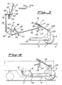
- Figure 1 shows an embodiment wherein the brush actuating motor is an electric motor.
- the levers (lever 5 in fig. 1) is L-shaped and comprises an arm on which said electric motor M is mounted.
- the shaft of the motor M bears a pulley PM around which a driving belt 8 is wound and, throug a pulley PS integral to the brush axis, directly transfers the movement of rotation to the brush 2, which movement results in the same direction as that of the vehicle on the surface to be cleaned.
- the floating arms 4 and 5 are placed in front of the brush 2 considering the direction of movement, and this fact, together with the direction of rotation of the brush, might lead to a crawling of same.
- at least one of the arms is provided with means to control the working position of the brush as well as the width and frequency of the oscillations of said arm during the operation of the device.
- said means to control the working position of the brush comprise a rigid linkage (26, 27, 33, 34, 35) which connects the floating arm 5 with an operating lever 37 which is operable by the operator; an adjusting screw 42, 43, or similar means engageable by the lever 37 to limit its downward run; and a spring or similar elastic means which engages said linkage to push the floating arm 5 and therefore the brush 2 towards the ground.
- the means to control the width and frequency of the oscillations of brush 2 comprise a damper in engagement with the rigid linkage to control the width and frequency of the oscillations when the brush 2 (and the arm 5) is pushed upwards.
- the control of the width of the oscillations, or better of the translations that take place when the brush is stressed upwards, is ensured by a pivot-slot connection between two elements of said linkage, preferably between the two elements immediately upstream the arm 5.
- the funtion of spring and damper is performed by a single element, consisting of a pneumatic spring 49 which acts on a three-armed lever 34 present in said rigid linkage.
- the sequence of its elements is as follows: the brush 2 is rotatably mounted in 1 on an end of the horizontal portion of the arm 5, the other end of which is pivoted or articulated in 25 to the frame of the vehicle.
- the arm 5 is pivoted in 25A to an end of a rod or rigid tie rod 26, the other end of which is fastened by means of said pivot-slot connection to a vertical lever 27, floating with respect to the frame of the vehicle thanks to a pivot 28 present on the lower end of said lever.
- the slot 30 is provided in one head 29 integral to the rigid tie rod 26, and is slidingly engaged with a pivot 31 integral to the floating lever 27 in the vicinity of its upper end.
- the length of the slot is approximately of 20-30 mm.
- the floating lever 27 is articulated in 32 to a second driving rod 33, hinged to a first arm of a three-armed lever 34 pivoted in 44 to the frame of the vehicle.
- the second arm of the lever 34 is hinged to a control rod 35 which is pivoted in 36 to the lower end of the operating lever 37 having an L-configuration and comprising an upper section 39 ending with a knob 41 to be actuated by the operator, and a shorter lower section 38.
- the operating lever 37 is furthermore pivoted in 40 to the frame of the vehicle and its upper end is movable in an elbow guide 37A between an operative position when the brush is lowered and a rest position with lifted brush.
- an adjusting screw 42 is provided, which is screwed in a seat or nut screw 43 integral with the frame, in a way to limit the maximum downward displacement of the lower section of the operating lever 37.
- the third arm integral to the lever 34, as indicated by reference 45, is connected through a movable stem 50 to said pneumatic spring or gas spring 49 which is pivoted at its other end, in 51, to the frame of the vehicle.
- the articulation of lever 34 is of the so-called shackle type, with the lever 47 rigidly fastened in 46 to the arm 45 of the lever 34 by means of a screw and with its free end pivoted in 48 to the stem of the gas spring 49.
- the screw 46 By loosening the screw 46 and rotating the section 47, it is possible to change the length of the lever arm, and therefore to vary the load of the gas spring 49.
- the gas spring 49 performs a double function in that it acts as a damper and moreover applies a load to the brush in such a way to provide the necessary strength to avoid the brush jumping. The use of separate damper and spring is thus avoided.
- the brush 20 is kept raised from the ground S, and this is obtained by the operator engaging the operating lever 37 in the non operative position of the elbow guide.
- the operating lever 37 is released and brought to said working position of the guide 37A and the linkage, which constitutes a rigid mechanically connected group, lowers.
- the gas spring 49 continues to exert a thrust F directed according to its own axis, which determines a couple with respect to the fulcrum 44 of the rigid lever system represented by the linkage group.
- the adjusting screw 42 is screwed and the lever 37 is released allowing the gas spring 49 to push the brush 20 against the ground, then the adjusting screw 42 is moved again until its end is in contact with the portion 38 of the lever 37.
- the motorised device is provided with means to adjust in horizontal direction the position of the brush to compensate its wear during its useful life, keeping it at the proper distance from the front wall of the brush box.
- the free end of the floating ⁇ ever is preferable mounted on an arm 11, turnable around the fulcrum 10 to position at least in horizontal direction the brush 2 with respect to the frame of the vehicle.
- the position of the free end 25 of the arm 11, where the floating lever 5 is pivoted, can be controlled in any known way, for instance by means of a cam.
- said position is controlled by an arm 11 pivoted in 10 and kept in position by a locking system 12.
- the lever 11 pivoted in 10 moves according to a circumference arc displacing the end 25 ahead and downwards, carrying the worn brush to gently rest on the front wall of the brush box and simultaneously on the ground, as indicated by dashed lines in figure 4.
- lever 11 The movement of lever 11 is caused by the weight of the elements hanging thereto (namely the brush 2 and the arm 5) and can be possibly helped by an elastic member (not shown).
Landscapes
- Engineering & Computer Science (AREA)
- Architecture (AREA)
- Civil Engineering (AREA)
- Structural Engineering (AREA)
- Vehicle Cleaning, Maintenance, Repair, Refitting, And Outriggers (AREA)
- Cleaning In General (AREA)
- Cleaning Of Streets, Tracks, Or Beaches (AREA)
Applications Claiming Priority (2)
| Application Number | Priority Date | Filing Date | Title |
|---|---|---|---|
| IT02062890A IT1248733B (it) | 1990-06-13 | 1990-06-13 | Dispositivo motorizzato per la pulizia di grandi superfici |
| IT2062890 | 1990-06-13 |
Publications (2)
| Publication Number | Publication Date |
|---|---|
| EP0462076A1 true EP0462076A1 (de) | 1991-12-18 |
| EP0462076B1 EP0462076B1 (de) | 1994-12-07 |
Family
ID=11169768
Family Applications (1)
| Application Number | Title | Priority Date | Filing Date |
|---|---|---|---|
| EP91830246A Expired - Lifetime EP0462076B1 (de) | 1990-06-13 | 1991-06-07 | Kraftfahrzeug zum Reinigen grosser Oberflächen |
Country Status (5)
| Country | Link |
|---|---|
| EP (1) | EP0462076B1 (de) |
| AT (1) | ATE115218T1 (de) |
| DE (1) | DE69105636T2 (de) |
| ES (1) | ES2067911T3 (de) |
| IT (1) | IT1248733B (de) |
Cited By (2)
| Publication number | Priority date | Publication date | Assignee | Title |
|---|---|---|---|---|
| EP0866172A3 (de) * | 1997-03-18 | 1999-05-19 | Applied Sweepers Limited | Saug- und Kehrvorrichtung |
| WO2022055492A1 (en) * | 2020-09-10 | 2022-03-17 | Jay Hirshberg | Object-gathering apparatus |
Citations (6)
| Publication number | Priority date | Publication date | Assignee | Title |
|---|---|---|---|---|
| US1369106A (en) * | 1917-01-27 | 1921-02-22 | Motorcycle Sweeper Company | Street-sweeper |
| DE704922C (de) * | 1937-01-28 | 1941-04-10 | Streicher Eisen U Stahlgiesser | Strassenkehrmaschine |
| DE2455200A1 (de) * | 1974-11-21 | 1976-05-26 | Kibo Kommunalmasch Gmbh & Co | Regelungsanordnung |
| GB2126633A (en) * | 1979-11-17 | 1984-03-28 | Hestair Eagle Ltd | Road sweeping apparatus |
| EP0134409A2 (de) * | 1983-09-09 | 1985-03-20 | Fmc Corporation | Konstanthalten der Kehrkontakt-Fläche eines Aufnehmbesens |
| FR2627787A1 (fr) * | 1988-02-26 | 1989-09-01 | Roussel Henri Pierre | Balayeuse-nettoyeuse de sols a conducteur accompagnant |
-
1990
- 1990-06-13 IT IT02062890A patent/IT1248733B/it active IP Right Grant
-
1991
- 1991-06-07 ES ES91830246T patent/ES2067911T3/es not_active Expired - Lifetime
- 1991-06-07 AT AT91830246T patent/ATE115218T1/de not_active IP Right Cessation
- 1991-06-07 EP EP91830246A patent/EP0462076B1/de not_active Expired - Lifetime
- 1991-06-07 DE DE69105636T patent/DE69105636T2/de not_active Expired - Fee Related
Patent Citations (6)
| Publication number | Priority date | Publication date | Assignee | Title |
|---|---|---|---|---|
| US1369106A (en) * | 1917-01-27 | 1921-02-22 | Motorcycle Sweeper Company | Street-sweeper |
| DE704922C (de) * | 1937-01-28 | 1941-04-10 | Streicher Eisen U Stahlgiesser | Strassenkehrmaschine |
| DE2455200A1 (de) * | 1974-11-21 | 1976-05-26 | Kibo Kommunalmasch Gmbh & Co | Regelungsanordnung |
| GB2126633A (en) * | 1979-11-17 | 1984-03-28 | Hestair Eagle Ltd | Road sweeping apparatus |
| EP0134409A2 (de) * | 1983-09-09 | 1985-03-20 | Fmc Corporation | Konstanthalten der Kehrkontakt-Fläche eines Aufnehmbesens |
| FR2627787A1 (fr) * | 1988-02-26 | 1989-09-01 | Roussel Henri Pierre | Balayeuse-nettoyeuse de sols a conducteur accompagnant |
Cited By (3)
| Publication number | Priority date | Publication date | Assignee | Title |
|---|---|---|---|---|
| EP0866172A3 (de) * | 1997-03-18 | 1999-05-19 | Applied Sweepers Limited | Saug- und Kehrvorrichtung |
| WO2022055492A1 (en) * | 2020-09-10 | 2022-03-17 | Jay Hirshberg | Object-gathering apparatus |
| US11965297B2 (en) | 2020-09-10 | 2024-04-23 | Jay Hirshberg | Object-gathering apparatus |
Also Published As
| Publication number | Publication date |
|---|---|
| EP0462076B1 (de) | 1994-12-07 |
| ES2067911T3 (es) | 1995-04-01 |
| IT9020628A1 (it) | 1991-12-13 |
| DE69105636T2 (de) | 1995-04-06 |
| ATE115218T1 (de) | 1994-12-15 |
| DE69105636D1 (de) | 1995-01-19 |
| IT1248733B (it) | 1995-01-26 |
| IT9020628A0 (de) | 1990-06-13 |
Similar Documents
| Publication | Publication Date | Title |
|---|---|---|
| US6199637B1 (en) | Subsoiling machine | |
| US4736575A (en) | Ride-on rotary lawnmower | |
| US11174607B2 (en) | Apparatus for collecting garbage and debris for a motor-sweeper | |
| US4525888A (en) | Maintaining constant pick-up broom pattern | |
| FR2612363A1 (fr) | Dispositif de coupe de vegetation | |
| EP0462076A1 (de) | Kraftfahrzeug zum Reinigen grosser Oberflächen | |
| US2749564A (en) | Attachment for sweeper | |
| CA2263024C (en) | Four bar linkage mounting for mowers | |
| JP3863641B2 (ja) | 除雪機の除雪高さ調節機構 | |
| EP0574600B1 (de) | Tragvorrichtung für einen Förderbandreiniger | |
| US10492655B2 (en) | Apparatus for collecting garbage and debris for a motor-sweeper | |
| EP0887468B1 (de) | Motorisierte Kehrmaschine | |
| EP0751736B1 (de) | Vorrichtung zur niveauregulierung und druckanpassung einer kehrwalze in einer industriellen kehrmaschine | |
| US3011193A (en) | Street sweeping machine | |
| JP3443823B2 (ja) | ブラシ支持装置 | |
| JPH07158012A (ja) | 舗装車両における回転式スクレーパ装置 | |
| US4140197A (en) | Trojan bar suspension device | |
| JP3703659B2 (ja) | 除雪機のベルトテンション機構 | |
| JP2004019098A (ja) | 清掃機のブラシ支持装置 | |
| KR950006498Y1 (ko) | 로타리의 캠식 작업깊이 조절장치 | |
| JP6865662B2 (ja) | 歩行型作業機 | |
| JPH05163711A (ja) | 床面清掃車 | |
| JP2002173922A (ja) | 除雪機の高低調節装置 | |
| CN120755333A (zh) | 一种铸造用倾转装置 | |
| AU624764B1 (en) | Apparatus for supporting belt cleaners |
Legal Events
| Date | Code | Title | Description |
|---|---|---|---|
| PUAI | Public reference made under article 153(3) epc to a published international application that has entered the european phase |
Free format text: ORIGINAL CODE: 0009012 |
|
| AK | Designated contracting states |
Kind code of ref document: A1 Designated state(s): AT CH DE ES FR GB IT LI NL |
|
| 17P | Request for examination filed |
Effective date: 19920611 |
|
| 17Q | First examination report despatched |
Effective date: 19930730 |
|
| RAP1 | Party data changed (applicant data changed or rights of an application transferred) |
Owner name: PULIMAT S.P.A. |
|
| ITF | It: translation for a ep patent filed | ||
| GRAA | (expected) grant |
Free format text: ORIGINAL CODE: 0009210 |
|
| AK | Designated contracting states |
Kind code of ref document: B1 Designated state(s): AT CH DE ES FR GB IT LI NL |
|
| REF | Corresponds to: |
Ref document number: 115218 Country of ref document: AT Date of ref document: 19941215 Kind code of ref document: T |
|
| REF | Corresponds to: |
Ref document number: 69105636 Country of ref document: DE Date of ref document: 19950119 |
|
| ET | Fr: translation filed | ||
| REG | Reference to a national code |
Ref country code: ES Ref legal event code: FG2A Ref document number: 2067911 Country of ref document: ES Kind code of ref document: T3 |
|
| PLBE | No opposition filed within time limit |
Free format text: ORIGINAL CODE: 0009261 |
|
| STAA | Information on the status of an ep patent application or granted ep patent |
Free format text: STATUS: NO OPPOSITION FILED WITHIN TIME LIMIT |
|
| 26N | No opposition filed | ||
| REG | Reference to a national code |
Ref country code: CH Ref legal event code: PFA Free format text: PULIMAT S.P.A.;PATENTANWAELTE SCHAAD, BALASS, MENZL & PARTNER AG TRANSFER- PATENTANWAELTE SCHAAD, BALASS, MENZL & PARTNER AG;ELECTROLUX EUROCLEAN S.P.A. Ref country code: CH Ref legal event code: NV |
|
| NLT1 | Nl: modifications of names registered in virtue of documents presented to the patent office pursuant to art. 16 a, paragraph 1 |
Owner name: ELECTROLUX EUROCLEAN ITALIA S.P.A. |
|
| REG | Reference to a national code |
Ref country code: FR Ref legal event code: CD |
|
| PGFP | Annual fee paid to national office [announced via postgrant information from national office to epo] |
Ref country code: FR Payment date: 19970510 Year of fee payment: 7 |
|
| PGFP | Annual fee paid to national office [announced via postgrant information from national office to epo] |
Ref country code: AT Payment date: 19970515 Year of fee payment: 7 |
|
| REG | Reference to a national code |
Ref country code: ES Ref legal event code: PC2A |
|
| PGFP | Annual fee paid to national office [announced via postgrant information from national office to epo] |
Ref country code: GB Payment date: 19970520 Year of fee payment: 7 |
|
| PGFP | Annual fee paid to national office [announced via postgrant information from national office to epo] |
Ref country code: DE Payment date: 19970523 Year of fee payment: 7 |
|
| PGFP | Annual fee paid to national office [announced via postgrant information from national office to epo] |
Ref country code: NL Payment date: 19970526 Year of fee payment: 7 |
|
| PGFP | Annual fee paid to national office [announced via postgrant information from national office to epo] |
Ref country code: CH Payment date: 19970603 Year of fee payment: 7 |
|
| PGFP | Annual fee paid to national office [announced via postgrant information from national office to epo] |
Ref country code: ES Payment date: 19970612 Year of fee payment: 7 |
|
| PG25 | Lapsed in a contracting state [announced via postgrant information from national office to epo] |
Ref country code: GB Free format text: LAPSE BECAUSE OF NON-PAYMENT OF DUE FEES Effective date: 19980607 Ref country code: AT Free format text: LAPSE BECAUSE OF NON-PAYMENT OF DUE FEES Effective date: 19980607 |
|
| PG25 | Lapsed in a contracting state [announced via postgrant information from national office to epo] |
Ref country code: ES Free format text: LAPSE BECAUSE OF EXPIRATION OF PROTECTION Effective date: 19980608 |
|
| PG25 | Lapsed in a contracting state [announced via postgrant information from national office to epo] |
Ref country code: LI Free format text: LAPSE BECAUSE OF NON-PAYMENT OF DUE FEES Effective date: 19980630 Ref country code: CH Free format text: LAPSE BECAUSE OF NON-PAYMENT OF DUE FEES Effective date: 19980630 |
|
| PG25 | Lapsed in a contracting state [announced via postgrant information from national office to epo] |
Ref country code: NL Free format text: LAPSE BECAUSE OF NON-PAYMENT OF DUE FEES Effective date: 19990101 |
|
| GBPC | Gb: european patent ceased through non-payment of renewal fee |
Effective date: 19980607 |
|
| REG | Reference to a national code |
Ref country code: CH Ref legal event code: PL |
|
| PG25 | Lapsed in a contracting state [announced via postgrant information from national office to epo] |
Ref country code: FR Free format text: LAPSE BECAUSE OF NON-PAYMENT OF DUE FEES Effective date: 19990226 |
|
| NLV4 | Nl: lapsed or anulled due to non-payment of the annual fee |
Effective date: 19990101 |
|
| PG25 | Lapsed in a contracting state [announced via postgrant information from national office to epo] |
Ref country code: DE Free format text: LAPSE BECAUSE OF NON-PAYMENT OF DUE FEES Effective date: 19990401 |
|
| REG | Reference to a national code |
Ref country code: FR Ref legal event code: ST |
|
| REG | Reference to a national code |
Ref country code: ES Ref legal event code: FD2A Effective date: 20000301 |
|
| PG25 | Lapsed in a contracting state [announced via postgrant information from national office to epo] |
Ref country code: IT Free format text: LAPSE BECAUSE OF NON-PAYMENT OF DUE FEES;WARNING: LAPSES OF ITALIAN PATENTS WITH EFFECTIVE DATE BEFORE 2007 MAY HAVE OCCURRED AT ANY TIME BEFORE 2007. THE CORRECT EFFECTIVE DATE MAY BE DIFFERENT FROM THE ONE RECORDED. Effective date: 20050607 |