EP0462090A1 - Procédure et construction de docteur pour l'élimination d'eau dans les perforations des rouleaux aspirants - Google Patents
Procédure et construction de docteur pour l'élimination d'eau dans les perforations des rouleaux aspirants Download PDFInfo
- Publication number
- EP0462090A1 EP0462090A1 EP91850157A EP91850157A EP0462090A1 EP 0462090 A1 EP0462090 A1 EP 0462090A1 EP 91850157 A EP91850157 A EP 91850157A EP 91850157 A EP91850157 A EP 91850157A EP 0462090 A1 EP0462090 A1 EP 0462090A1
- Authority
- EP
- European Patent Office
- Prior art keywords
- suction roll
- doctor blade
- face
- doctor
- blade
- Prior art date
- Legal status (The legal status is an assumption and is not a legal conclusion. Google has not performed a legal analysis and makes no representation as to the accuracy of the status listed.)
- Granted
Links
Images
Classifications
-
- D—TEXTILES; PAPER
- D21—PAPER-MAKING; PRODUCTION OF CELLULOSE
- D21G—CALENDERS; ACCESSORIES FOR PAPER-MAKING MACHINES
- D21G3/00—Doctors
- D21G3/005—Doctor knifes
-
- D—TEXTILES; PAPER
- D21—PAPER-MAKING; PRODUCTION OF CELLULOSE
- D21F—PAPER-MAKING MACHINES; METHODS OF PRODUCING PAPER THEREON
- D21F3/00—Press section of machines for making continuous webs of paper
- D21F3/02—Wet presses
- D21F3/10—Suction rolls, e.g. couch rolls
Definitions
- the invention concerns a doctor for a suction roll in a paper machine.
- doctor solutions are known in which a doctor is fitted to remove water that has remained in the perforations in the suction roll out of said perforations.
- the prior-art solutions are not sufficiently efficient. It follows from this that, out of the perforations in the suction roll, water still moves back into the felt and, thus, wetting of the felt occurs.
- the range of the angle ⁇ between the face plane of the doctor blade and the tangential direction of the suction roll in the area of the outlet side of the doctor blade is 2... 10°. If the range of the angle is larger or smaller than said number of degrees, the desired suction effect is not produced.
- the frame of the doctor blade is fitted to be pivotal on an articulation point, and it has been fitted so that it can be set against the suction roll by means of the force produced by a loading hose.
- the doctor blade itself, its frame part, is attached to a fixed base frame resiliently so that the doctor blade can be made to comply with the face form of the suction roll in all directions of width.
- a plastic rib is used as the doctor blade.
- the method in accordance with the invention for removing water out of a suction roll is mainly characterized in that the doctor blade is mounted with its slat face in such an angular position in relation to the face of the suction roll that the angle between the face plane of the doctor blade and the tangential direction of the face of the suction roll, when the tangent is drawn at the contact point between the tip of the doctor blade and the face of the suction roll, is within a range of 2...
- the doctor blade in accordance with the invention which is to be placed against the suction roll, is mainly characterized in that the doctor construction comprises a slat-shaped doctor blade, which comprises a slat face, at which the angle between the face plane of said slat face and the tangential direction of the face of the suction roll which is jointly operative with the doctor blade is within a range of 2... 10°, whereby an area of negative pressure is formed by means of the doctor blade in accordance with the invention between the face of the doctor blade and the face of the suction roll, water being removed by means of the negative pressure efficiently out of the perforations and/or grooves in the suction roll.
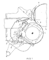
- Figure 1 is a schematic illustration of the area involving the solution in accordance with the invention.
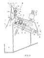
- Figure 2 is a side view of a doctor in accordance with the invention.
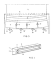
- Figure 3 is a sectional view taken along the line I-I in Fig. 2.
- Figure 4 is an axonometric view of a doctor blade.
- Fig. 1 shows a doctor construction 10 in accordance with the invention as fitted in its object of use.
- the doctor construction 10 is fitted in connection with a suction roll jointly operative with a granite roll in the area of the outlet side of a nip N.
- the senses of rotation of the rolls are indicated by arrows.
- the run of the felt H is denoted with the arrow L1
- the run of the paper web with the arrow L2.
- the doctor construction 10 is fitted to remove water from the outlet side of the nip N between the suction roll T, and the granite roll T2, and in particular the doctor 10 is fitted to remove water out of the perforations in the suction roll.
- water is also removed out of the space placed ahead of the doctor blade 11 as the front edge D of the doctor blade 11 guides the flow of the drain water into the sewer system M in the way indicated by the arrow E1.
- the active effect of the doctor blade is produced by the fact that it has been realized to regulate the angle between the face C of the doctor blade and the face of the suction roll to the range of 2... 10°, whereby in the space V between the face plane C of the doctor blade and the face plane T1′ of the roll T1 a negative pressure is formed (in Fig. 2), which absorbs water efficiently out of the perforations in the suction roll.
- Fig. 2 is a more detailed illustration of the doctor construction.
- a space V remains, in which a negative pressure is formed, which absorbs water efficiently out of the perforations F in the suction roll T1.
- the angle a between the face C of the doctor blade 11 and the tangent of the face T1′ of the suction roll jointly operative with the doctor blade in the area of the outlet side from the contact point between the suction roll and the doctor blade 11, seen in the sense of rotation of the suction roll is in the range of 2... 10°. Said range of degrees is optimal, an in said range an active suction effect is achieved, in which case, in the way illustrated in Fig.
- the water is absorbed out of the perforations F and falls down into the drain trough K.
- the slanting blade face D above the doctor blade 11 also collects flowing water and guides said water over the doctor blade construction to be passed, in the way indicated by the arrow E1, into the drain trough and further out of contact with the constructions.
- the doctor blade 11 is an oblong construction, which is preferably made of plastic and which is attached to the blade frame 12 by means of its holder 11a.
- a T-rail fastening, a dovetail joint, or an equivalent mode of joining is employed, in which case, when a grasping threading 11b is grasped by means of a tool, the doctor blade 11 can be pulled apart from the blade frame 12.
- a lock screw 11c prevents falling off of the doctor blade out of a counter-holder 12a fitted on the blade frame 12.
- the blade frame 12 is fitted to pivot on support of the articulation point 13, and said pivoting is produced by displacing a loading piece 14 by means of loading hoses 15.
- a deformation is produced in the loading hoses by passing compressed air into the loading hoses through a hose 16.
- the doctor is opened "by its own weight” when the pressure is discharged from the loading hoses.
- the articulated joint 13 is placed in the base frame 17, on which the loading-hose means are also fitted.
- the whole constructional solution is fixed to the frame part 18 placed underneath by means of screw devices 19.
- the basic frame 17 is loaded by means of screw devices 20 while the screw is guided by means of the threading in the bracket 20′.
- the screw device 20 the desired transverse deflection is obtained for the base frame 17 and for its articulation points 13, said deformation being transferred further through the blade frame 12 to the blade 11 itself.
- the shape of the tip of the blade 11 can be made to comply with the transverse profile and the crown form of the suction roll across the entire width of the suction roll. Said circumstance is essential if a negative pressure of the correct magnitude is to be provided in the space V between the doctor blade 11 and the face T1′ of the suction roll T1.
- the counter-screw is denoted with the reference numeral 21.
- the counter-screw can be displaced in the bracket 22 and locked by means of a screw 23 in the desired position.
- a protective shield 24 By means of a protective shield 24, any splash water and water that flows from the upper face of the blade 11 are passed into the drain system and sewer system M.
- Fig. 3 is a sectional view taken along the line I-I in Fig. 2.
- the base frame 17 is given the desired transverse shape.
- the base frame 17 is attached to the frame part 18 by means of screws 19 fitted into screw openings 25a provided in gaps 25 open from the side.
- the gaps make it possible that the base frame 17 and, thereby, the blade 11 can be deflected, when tensioned by the loading screws 19, into the shape corresponding to the desired crown form.
- Fig. 4 is an axonometric view of a doctor blade 11 made of plastic. By grasping the grasping threading 11b by means of a tool, the doctor blade is passed in the transverse direction out of the counter-holder 12a of the blade frame 12.
Landscapes
- Paper (AREA)
- Cleaning By Liquid Or Steam (AREA)
- Measurement Of Radiation (AREA)
- Stabilization Of Oscillater, Synchronisation, Frequency Synthesizers (AREA)
- Control Of Motors That Do Not Use Commutators (AREA)
Applications Claiming Priority (2)
| Application Number | Priority Date | Filing Date | Title |
|---|---|---|---|
| FI902910A FI87095C (fi) | 1990-06-11 | 1990-06-11 | Skavare till en sugvals |
| FI902910 | 1990-06-11 |
Publications (2)
| Publication Number | Publication Date |
|---|---|
| EP0462090A1 true EP0462090A1 (fr) | 1991-12-18 |
| EP0462090B1 EP0462090B1 (fr) | 1995-10-18 |
Family
ID=8530609
Family Applications (1)
| Application Number | Title | Priority Date | Filing Date |
|---|---|---|---|
| EP91850157A Expired - Lifetime EP0462090B1 (fr) | 1990-06-11 | 1991-06-10 | Procédure et construction de docteur pour l'élimination d'eau dans les perforations des rouleaux aspirants |
Country Status (6)
| Country | Link |
|---|---|
| US (1) | US5178731A (fr) |
| EP (1) | EP0462090B1 (fr) |
| AT (1) | ATE129304T1 (fr) |
| CA (1) | CA2043842C (fr) |
| DE (1) | DE69113870T2 (fr) |
| FI (1) | FI87095C (fr) |
Cited By (2)
| Publication number | Priority date | Publication date | Assignee | Title |
|---|---|---|---|---|
| EP3336248A1 (fr) * | 2016-12-19 | 2018-06-20 | PMT Italia S.p.A. | Dispositif de presse |
| CN108203891A (zh) * | 2016-12-20 | 2018-06-26 | Pmt意大利股份有限公司 | 压榨装置 |
Families Citing this family (6)
| Publication number | Priority date | Publication date | Assignee | Title |
|---|---|---|---|---|
| FI3832U1 (fi) * | 1998-11-16 | 1999-03-16 | Valmet Corp | Imutelan kaavin erityisesti paperikoneisiin |
| US6592721B1 (en) | 1999-05-12 | 2003-07-15 | International Paper Company | Apparatus for dewatering a suction papermaking roll |
| US6202252B1 (en) | 1999-06-03 | 2001-03-20 | Valmet Ltd. | Doctoring apparatus |
| FI20095815A7 (fi) | 2009-07-29 | 2011-01-30 | Metso Paper Inc | Kaavintaväline kuiturainakonetta varten ja kaavinsovitelma kuiturainakoneessa |
| EP3568054A4 (fr) * | 2017-01-13 | 2021-03-24 | Cornell University | Méthode et appareil de manipulation de la paroi latérale d'une lumière corporelle ou d'une cavité corporelle en vue de fournir une meilleure visualisation de celle-ci, et/ou un meilleur accès à celle-ci, et/ou une stabilisation d'instruments par rapport à celle-ci |
| DE102022113503A1 (de) * | 2022-05-30 | 2023-11-30 | Voith Patent Gmbh | Schaberhalter und Schabvorrichtung |
Citations (2)
| Publication number | Priority date | Publication date | Assignee | Title |
|---|---|---|---|---|
| FR1455562A (fr) * | 1965-11-18 | 1966-04-01 | Escher Wyss Gmbh | Machine à tamis circulaire à zone de formation de feuille raccourcie |
| US3829927A (en) * | 1972-05-04 | 1974-08-20 | Vickerys Ltd | Doctors for paper making machines |
Family Cites Families (8)
| Publication number | Priority date | Publication date | Assignee | Title |
|---|---|---|---|---|
| US2477339A (en) * | 1945-02-14 | 1949-07-26 | Lodding Engineering Corp | Doctor mechanism for rolls and cylinders |
| US2858747A (en) * | 1955-02-07 | 1958-11-04 | Wagner Rudolf Ernst | Rotary presses and the like |
| US3128207A (en) * | 1961-09-07 | 1964-04-07 | Beloit Iron Works | Trailing blade coater blade loading mechanism |
| US3198693A (en) * | 1964-08-21 | 1965-08-03 | Beloit Corp | Scavenging means for grooved press rolls |
| US3381607A (en) * | 1966-08-01 | 1968-05-07 | Mead Corp | Process and apparatus for removing liquid from a moving web of paper and the like |
| US4151797A (en) * | 1977-05-04 | 1979-05-01 | Mid America Tag And Label Company, Inc. | Doctor blade apparatus |
| GB8309530D0 (en) * | 1983-04-08 | 1983-05-11 | Beloit Walmsley Ltd | Paper forming |
| US4789432A (en) * | 1987-06-08 | 1988-12-06 | Thermo Electron Web Systems, Inc. | Doctoring apparatus |
-
1990
- 1990-06-11 FI FI902910A patent/FI87095C/fi active IP Right Grant
-
1991
- 1991-05-30 US US07/707,462 patent/US5178731A/en not_active Expired - Lifetime
- 1991-06-04 CA CA002043842A patent/CA2043842C/fr not_active Expired - Fee Related
- 1991-06-10 AT AT91850157T patent/ATE129304T1/de not_active IP Right Cessation
- 1991-06-10 EP EP91850157A patent/EP0462090B1/fr not_active Expired - Lifetime
- 1991-06-10 DE DE69113870T patent/DE69113870T2/de not_active Expired - Fee Related
Patent Citations (2)
| Publication number | Priority date | Publication date | Assignee | Title |
|---|---|---|---|---|
| FR1455562A (fr) * | 1965-11-18 | 1966-04-01 | Escher Wyss Gmbh | Machine à tamis circulaire à zone de formation de feuille raccourcie |
| US3829927A (en) * | 1972-05-04 | 1974-08-20 | Vickerys Ltd | Doctors for paper making machines |
Cited By (2)
| Publication number | Priority date | Publication date | Assignee | Title |
|---|---|---|---|---|
| EP3336248A1 (fr) * | 2016-12-19 | 2018-06-20 | PMT Italia S.p.A. | Dispositif de presse |
| CN108203891A (zh) * | 2016-12-20 | 2018-06-26 | Pmt意大利股份有限公司 | 压榨装置 |
Also Published As
| Publication number | Publication date |
|---|---|
| DE69113870T2 (de) | 1996-04-04 |
| EP0462090B1 (fr) | 1995-10-18 |
| ATE129304T1 (de) | 1995-11-15 |
| US5178731A (en) | 1993-01-12 |
| FI902910A0 (fi) | 1990-06-11 |
| FI902910L (fi) | 1991-12-12 |
| FI87095B (fi) | 1992-08-14 |
| FI87095C (fi) | 1992-11-25 |
| DE69113870D1 (de) | 1995-11-23 |
| CA2043842C (fr) | 1995-06-13 |
Similar Documents
| Publication | Publication Date | Title |
|---|---|---|
| EP0462090B1 (fr) | Procédure et construction de docteur pour l'élimination d'eau dans les perforations des rouleaux aspirants | |
| RU2426653C2 (ru) | Система удаления краски, предназначенная для печатной машины | |
| US7713384B2 (en) | Device for detachably fixing a holder for a doctor blade in a paper production plant | |
| JP2012515859A (ja) | 製紙機の改善された脱水性能をもたらすシステムおよび方法 | |
| US4537130A (en) | Stripper for a roller cleaning device | |
| JPH05228412A (ja) | 繊維質帯状体のための塗布装置 | |
| CN101910514A (zh) | 用于使幅材引领尾部脱离纤维幅材机中的移动表面的方法、刀架和刮刀设备 | |
| NO313842B1 (no) | Stövfjerningsinstallasjon pÕ maskin som produserer kreppapir | |
| EP0682992A2 (fr) | Méthode et dispositif pour l'enlèvement et la collection de poussière séparée d'une bande pour une machine à papier ou une machine de finition du papier | |
| JP3716168B2 (ja) | 抄紙機用のクリーニング装置 | |
| CA1247359A (fr) | Dispositif d'enduction biface du papier en feuille | |
| US4698134A (en) | Method for cleaning papermaking fabrics | |
| EP0763624B1 (fr) | Dispositif de lavage d'une toile dans une machine à papier ou carton | |
| EP0452655A1 (fr) | Dispositif dans une machine à papier | |
| EP2649236B1 (fr) | Porte-racle | |
| US6146502A (en) | Paper making machine with a traveling deckle board | |
| KR0159312B1 (ko) | 로울 세척장치 | |
| US5935386A (en) | Suction roll box | |
| US5354426A (en) | Apparatus and method for removing debris from forming wire | |
| WO2006090014A1 (fr) | Disposition dans la section de presse d’une machine de formation de bandes et racle | |
| US6353972B2 (en) | Apparatus for cleaning traveling flat bars of a carding machine | |
| JP4159786B2 (ja) | ドクター装置 | |
| JP2000170089A (ja) | プレストップロール用ドクター装置 | |
| US20070089848A1 (en) | Dewatering Arrangement on the Press Section of a Web-Forming Machine | |
| FI118814B (fi) | Menetelmä ja sovitelma kuiturainan käsittelemiseksi ennen kalanteria |
Legal Events
| Date | Code | Title | Description |
|---|---|---|---|
| PUAI | Public reference made under article 153(3) epc to a published international application that has entered the european phase |
Free format text: ORIGINAL CODE: 0009012 |
|
| 17P | Request for examination filed |
Effective date: 19910930 |
|
| AK | Designated contracting states |
Kind code of ref document: A1 Designated state(s): AT DE FR GB IT SE |
|
| 17Q | First examination report despatched |
Effective date: 19940810 |
|
| GRAA | (expected) grant |
Free format text: ORIGINAL CODE: 0009210 |
|
| AK | Designated contracting states |
Kind code of ref document: B1 Designated state(s): AT DE FR GB IT SE |
|
| REF | Corresponds to: |
Ref document number: 129304 Country of ref document: AT Date of ref document: 19951115 Kind code of ref document: T |
|
| REF | Corresponds to: |
Ref document number: 69113870 Country of ref document: DE Date of ref document: 19951123 |
|
| ITF | It: translation for a ep patent filed | ||
| ET | Fr: translation filed | ||
| PLBE | No opposition filed within time limit |
Free format text: ORIGINAL CODE: 0009261 |
|
| STAA | Information on the status of an ep patent application or granted ep patent |
Free format text: STATUS: NO OPPOSITION FILED WITHIN TIME LIMIT |
|
| 26N | No opposition filed | ||
| REG | Reference to a national code |
Ref country code: GB Ref legal event code: IF02 |
|
| PGFP | Annual fee paid to national office [announced via postgrant information from national office to epo] |
Ref country code: AT Payment date: 20080616 Year of fee payment: 18 |
|
| PGFP | Annual fee paid to national office [announced via postgrant information from national office to epo] |
Ref country code: IT Payment date: 20080625 Year of fee payment: 18 |
|
| PGFP | Annual fee paid to national office [announced via postgrant information from national office to epo] |
Ref country code: SE Payment date: 20080612 Year of fee payment: 18 Ref country code: DE Payment date: 20080620 Year of fee payment: 18 |
|
| PGFP | Annual fee paid to national office [announced via postgrant information from national office to epo] |
Ref country code: FR Payment date: 20080613 Year of fee payment: 18 |
|
| PGFP | Annual fee paid to national office [announced via postgrant information from national office to epo] |
Ref country code: GB Payment date: 20080620 Year of fee payment: 18 |
|
| GBPC | Gb: european patent ceased through non-payment of renewal fee |
Effective date: 20090610 |
|
| REG | Reference to a national code |
Ref country code: FR Ref legal event code: ST Effective date: 20100226 |
|
| PG25 | Lapsed in a contracting state [announced via postgrant information from national office to epo] |
Ref country code: FR Free format text: LAPSE BECAUSE OF NON-PAYMENT OF DUE FEES Effective date: 20090630 |
|
| PG25 | Lapsed in a contracting state [announced via postgrant information from national office to epo] |
Ref country code: GB Free format text: LAPSE BECAUSE OF NON-PAYMENT OF DUE FEES Effective date: 20090610 |
|
| PG25 | Lapsed in a contracting state [announced via postgrant information from national office to epo] |
Ref country code: AT Free format text: LAPSE BECAUSE OF NON-PAYMENT OF DUE FEES Effective date: 20090610 Ref country code: DE Free format text: LAPSE BECAUSE OF NON-PAYMENT OF DUE FEES Effective date: 20100101 |
|
| PG25 | Lapsed in a contracting state [announced via postgrant information from national office to epo] |
Ref country code: IT Free format text: LAPSE BECAUSE OF NON-PAYMENT OF DUE FEES Effective date: 20090610 |
|
| PG25 | Lapsed in a contracting state [announced via postgrant information from national office to epo] |
Ref country code: SE Free format text: LAPSE BECAUSE OF NON-PAYMENT OF DUE FEES Effective date: 20090611 |