EP0462341A1 - Synchronisiertes frequenzmoduliertes Verstärkersystem - Google Patents
Synchronisiertes frequenzmoduliertes Verstärkersystem Download PDFInfo
- Publication number
- EP0462341A1 EP0462341A1 EP90306817A EP90306817A EP0462341A1 EP 0462341 A1 EP0462341 A1 EP 0462341A1 EP 90306817 A EP90306817 A EP 90306817A EP 90306817 A EP90306817 A EP 90306817A EP 0462341 A1 EP0462341 A1 EP 0462341A1
- Authority
- EP
- European Patent Office
- Prior art keywords
- frequency modulated
- signal
- frequency
- broadcast
- transmitting
- Prior art date
- Legal status (The legal status is an assumption and is not a legal conclusion. Google has not performed a legal analysis and makes no representation as to the accuracy of the status listed.)
- Withdrawn
Links
Images



Classifications
-
- H—ELECTRICITY
- H04—ELECTRIC COMMUNICATION TECHNIQUE
- H04H—BROADCAST COMMUNICATION
- H04H20/00—Arrangements for broadcast or for distribution combined with broadcast
- H04H20/65—Arrangements characterised by transmission systems for broadcast
- H04H20/67—Common-wave systems, i.e. using separate transmitters operating on substantially the same frequency
-
- H—ELECTRICITY
- H03—ELECTRONIC CIRCUITRY
- H03L—AUTOMATIC CONTROL, STARTING, SYNCHRONISATION OR STABILISATION OF GENERATORS OF ELECTRONIC OSCILLATIONS OR PULSES
- H03L7/00—Automatic control of frequency or phase; Synchronisation
- H03L7/06—Automatic control of frequency or phase; Synchronisation using a reference signal applied to a frequency- or phase-locked loop
- H03L7/16—Indirect frequency synthesis, i.e. generating a desired one of a number of predetermined frequencies using a frequency- or phase-locked loop
- H03L7/22—Indirect frequency synthesis, i.e. generating a desired one of a number of predetermined frequencies using a frequency- or phase-locked loop using more than one loop
- H03L7/23—Indirect frequency synthesis, i.e. generating a desired one of a number of predetermined frequencies using a frequency- or phase-locked loop using more than one loop with pulse counters or frequency dividers
Definitions
- the present invention relates in general to a frequency modulated radio frequency synchronous repeater system for the transmission of frequency modulated broadcast signals, and more particularly to a frequency modulated radio frequency repeater system employing a synchronous frequency modulated booster system for the re-transmission of frequency modulated broadcast signals.
- Frequency modulated broadcast transmissions have been limited to audiences within a reception area.
- re-transmission sites have been installed in areas remotely located from the originating transmitter.
- booster transmitters and synchronous transmitter exciters were booster transmitters and synchronous transmitter exciters to increase the power level of the frequency modulated broadcast signals at a re-transmission site.
- phase shifts, delays and inconsistent modulation levels between the originating frequency modulated broadcast signal and the frequency modulated broadcast signal at the re-transmission site were used at a re-transmission site which caused phase shifts, delays and inconsistent modulation levels between the originating frequency modulated broadcast signal and the frequency modulated broadcast signal at the re-transmission site.
- Phase shifts, delays and inconsistent modulation levels between the originating frequency modulated radio frequency signal and the re-transmitted frequency modulated radio frequency signal resulted in signal degradation and noise interference in the coverage area intended for improvement by the re-transmitted frequency modulated broadcast signal of the booster transmitter.
- a device was employed to produce a reference signal for synchronizing and stabilizing the output of frequency modulated radio frequency signals transmitted at a re-transmission booster site.
- the device did not use a reference signal generated at the site of the originating transmitter or re-use the FM modulation in the original carrier.
- the output of the frequency modulated radio frequency signal of the transmitter at the re-transmission booster site was modified from the original FM signal in frequency and in phase.
- the output of the phase detector is a control signal which is proportional to the phase differences of the input signals to the phase detector.
- the error signal is applied to the voltage controlled crystal oscillator.
- the circuit described is part of a phase locked loop circuit.
- FM exciters were sold to accept the composite baseband signal from a stero generator, and STL system or monaural audio and SCA programming, and to generate its operating frequency with a digitally programmed, phase-locked frequency synthesis system.
- Such an FM exciter was sold by Continental Electronics Mfg. Co. of Dallas, Texas, as the Continental Type 802A FM exciter, and by Broadcast Electronics of Quincy, Illinois, as the Model FX-30.
- a synchronous frequency modulated booster system for a transmitter that re-transmits frequency modulated radio frequency signals at a booster site away from the originating program source.
- the synchronous frequency modulated booster system includes a synchronous FM transmitter exciter that converts incoming frequency modulated intermediate frequency signals transmitted at the site of an originating transmitter to the frequency modulated radio frequency signals transmitted by the originating transmitter and applies the frequency converted frequency modulated radio frequency modulated radio frequency signals to a booster transmitter that re-transmits the frequency modulated radio frequency signals.
- a synchronous frequency modulated booster system comprises a transmitter that re-transmits frequency modulated radio frequency signals.
- the synchronous frequency modulated booster system includes a synchronous FM exciter that receives an IF signal and a reference pilot signal generated at the originating transmitter for synchronizing the carrier frequency and modulation level of frequency modulated radio frequency signals applied to the transmitter for re-transmission with the frequency modulated radio frequency signals transmitted at the originating transmitter.
- An object of the present invention is to provide a method of synchronizing frequency modulated booster system for a transmitter that re-transmits frequency modulated radio frequency signals, which booster system includes a synchronous FM exciter for stabilizing the frequency of the booster transmitter, the baseband, group delays, and inconsistent modulation levels between frequency modulated radio frequency signals transmitted by an originating transmitter and the frequency modulated radio frequency signals re-transmitted from a remote transmitter.
- Another object of the present invention is to provide a synchronous frequency modulated booster system for a transmitter that re-transmits frequency modulated radio frequency signals
- booster system includes a synchronous FM exciter for receiving a reference signal from the site of the originating transmitter along with frequency modulated intermediate frequency signals for synchronizing the re-transmitted frequency modulated radio frequency signals with the frequency modulated radio frequency signals transmitted by the originating transmitter to preserve signal integrity and stability.
- Another object of the present invention is to provide an economical arrangement for intermediate frequency repeating transmitter links.
- a feature of the present invention is to obviate need for an additional subcarrier frequency which has been heretofore used for transmitting a synchronizing tone to lock the carrier frequency of the FM transmitter.
- Another feature of the present invention is that the modulation levels at all remote transmitters are synchronized.
- Another feature of the present invention is the minimization of audio phase delays for enhancing stereo quality.
- Another feature of the present invention is the elimination of an FM subcarrier to transmit a reference signal for synchronizing the frequency of the booster transmitter.
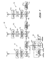
- Illustrated in Figure 1 is a serial feed frequency modulated radio frequency broadcast system or network 10 with boosters, which comprises an originating broadcast station 15 for broadcasting an originating frequency modulated radio frequency signal (FM) and re-transmitting broadcast stations 20 and 25 for re-transmitting, respectively, the frequency modulated radio frequency signals (FM) transmitted by the originating broadcast station 15.
- the re-transmitting broadcast stations 20 and 25 are on-site remotely located from the site of the originating broadcast station 15.
- the originating FM broadcast station 15 comprises a suitable studio 30, a conventional studio transmitter link (STL) receiver 35 with an intermediate frequency output, a synchronous FM exciter 40, and a conventional originating FM transmitter 45. Included in the studio 30 are an FM broadcast stereo generator 46, and conventional FM subcarrier generators for subsidiary communication authorization (SCA) equipment 47 and 48, all of which are connected to a conventional studio link (STL) transmitter 50 for transmitting a composite FM baseband signal from the studio to the originating broadcast station 15.
- SCA subsidiary communication authorization
- the FM broadcast stereo generator 46 is modified to accept a highly stable time base reference signal.
- This signal is 19 KHz or multiple of 19 KHz generated by a highly stable crystal oscillator, not shown, with a long term stability of 1 ppm per year.
- the highly stable crystal oscillator is included in the STL transmitter 50. In this manner, a highly stable time base reference signal is provided for phase locking the originating broadcast frequency and the rebroadcasting frequencies in the entire network 10 so that stability and accuracy of the broadcast frequencies are achieved.
- the output of the STL transmitter 50 is an FM signal which, in the exemplary embodiment, is a 950 megahertz (MHz) signal.
- the stereo generator 46 and the SCA equipment 47 and 48 modulate the carrier frequency generated by the STL transmitter 50 with the program to be broadcast to provide the FM signal of 950 MHz.
- the STL transmitter 50 applies a reference signal to the stereo generator 46.
- the reference signal is a 19 kilohertz (KHz) signal or a multiple of a 19 KHz frequency signal.
- the STL receiver 35 receives through a suitable studio link 55, the FM signal from the STL transmitter 50, and applies an FM signal to the synchronous FM exciter 40 and an FM signal to a conventional intermediate frequency (IF) STL transmitter or a one-way repeater 60.
- the FM signal applied to the synchronous FM exciter 40 from the STL receiver 35 is a 10.7 MHz signal and the FM signal applied to the IF repeater STL transmitter 60 is a 63 MHz signal, which is also the IF signal of the STL receiver 35.
- the studio link 55 in the exemplary embodiment, may be a conventional microwave link, telephone lines, or the like.
- the reference signal from the stereo generator 46 to the STL transmitter 50 is received by the STL receiver 35 with the 950 MHz signal and is present in both the 10.7 MHz signal applied to the synchronous FM exciter 40 and the 63 MHz signal applied to the IF STL transmitter 60.
- the synchronous FM exciter 40 which will be described in detail hereinafter, applies to the originating FM transmitter 45, an FM broadcast signal, the carrier frequency of which is generated by the synchronous FM exciter 40.
- the FM transmitter 45 transmits an FM broadcast signal in the range of 88 MHz-108 MHz.
- a conventional link 65 such as a microwave link, VHF or UHF link, inter-city relay and the like is employed for transmitting an FM IF signal to an STL receiver 70 of the re-transmitting FM broadcast booster station 20.
- the FM IF signal transmitted by the IF STL transmitter 60 is an FM 950 MHz signal.
- the IF STL transmitter 60 increases the carrier frequency from 63 MHz to 950 MHz, in the exemplary embodiment.
- the STL receiver 70 applies an FM signal to a synchronous FM exciter 75 of the re-transmitting station 20 and an FM signal to an IF repeater STL transmitter or one-way repeater 80 of the re-transmitting station 20.
- the signal applied to the synchronous FM exciter 75 in the exemplary embodiment, is 10.7 MHz FM signal with a 19 KHz reference signal in the composite baseband signals.
- the signal applied to the IF repeater STL transmitter 80 in the preferred embodiment, is 63 MHz FM signal with a 19 KHz reference signal in the composite baseband signals which is also the IF signal of the STL receiver 70.
- the synchronous FM exciter 75 which will be described in detail hereinafter, is similar in construction and operation to the synchronous FM exciter 40 of the originating transmission station 15.
- the output of the synchronous FM exciter 75 is an FM signal having a frequency in the range of 88 MHz-108 MHz.
- the output of the FM signal from the synchronous FM exciter 75 has the power level thereof amplified by the booster 85 to compensate for losses that may occur from the transmission of signals from the broadcast station 15 to the broadcast station 20 and increase the signal strength of the originating transmitter 15 without causing transmission interference with other booster stations of the network 10.
- the output signal of the re-transmitter 90 in the preferred embodiment, is in the range of 88 MHz-108 MHz.
- a conventional link 95 such as a microwave link, VHF or UHF link, inter-city relay and the like is employed for transmitting an FM IF signal to an STL receiver 100 of the re-transmitting FM broadcast booster station 25.
- the FM IF signal transmitted by the IF repeater STL transmitter 80 is an FM 950 MHz signal.
- the IF repeater STL transmitter increases the carrier frequency from 63 MHz to 960 MHz in the exemplary embodiment.
- the STL receiver 100 applies an FM signal to a synchronous FM exciter 105 of the re-transmitting station 25 and an FM signal to an IF repeater STL transmitter or one-way repeater 110 of a succeeding station.
- the signal applied to the synchronous FM exciter 105 in the exemplary embodiment, is a 10.7 MHz FM signal with a 19 KHz reference signal in the composite baseband frequencies.
- the signal applied to the IF repeater STL transmitter 110 in the preferred embodiment, is a 63 MHz FM signal with a 19 KHz reference signal in the composite baseband signals which is also the IF signal of the STL receiver 100.
- the synchronous FM exciter 105 which will be described in detail hereinafter, is similar in construction and operation to the synchronous FM exciter 75 of the re-transmission station 20.
- the output of the synchronous FM exciter 105 is an FM signal having a frequency in the range of 88 MHz-108 MHz.
- a suitable booster 115 of the re-transmission station 20 Connected to the output of the synchronous FM exciter 105 is a suitable booster 115 of the re-transmission station 20, which, in a conventional manner, amplifies the power of the FM signal applied to a re-transmitting or repeater transmitter 120 of the re-transmitting station 25.
- the output of the FM signal from the synchronous FM exciter 105 has the power level thereof amplified by the booster 115 to compensate for losses that may occur from the transmission of signals from the originating broadcast station 15 to the re-broadcast station 25 and, perhaps, increase the signal strength of the originating transmitter 15 without causing transmission interference with other booster stations of the network 10.
- the output signal of the re-transmitter 120 in the preferred embodiment, is in the range of 88 MHz-108 MHz.
- the studio STL transmitter 50 is in communication with the originating broadcast station 15, but is isolated from the FM re-broadcast stations 20 and 25 or any succeeding re-broadcast station of the network 10.
- the FM signal is transmitted successively from one transmitter to the succeeding transmitter in a serial fashion starting with the originating transmitter 45 and proceeding successively or in series in the order of proximity to the originating transmitter 45.
- FIG 2 Illustrated in Figure 2 is a parallel feed frequency modulated radio frequency broadcast system or network 125 with boosters, which is a modification of the FM radio frequency broadcast system or network 10 shown in Figure 1.
- Elements of the FM radio frequency system 125 similar in construction and operation to the elements of the FM radio frequency system or network 10 are designated with the same reference numeral but with a prime suffix.
- the FM radio frequency broadcast system 125 differs from the FM radio frequency broadcast system 10 in that the IF repeater STL transmitter 60 has been omitted.
- the STL transmitter 50' has the output thereof transmit the baseband composite signals directly to the STL receiver 70' of the re-transmitting broadcast station 20'.
- the originating transmitter 45' is boosted by the re-transmitting stations 20', 25' and any succeeding re-transmission station.
- the STL transmitter 50' of the studio 30' of the originating broadcast station 10' applies an FM signal to the STL receiver 35' of the originating broadcast station 10' and to the succeeding STL receiver 70' of the re-transmitting broadcast station 20'.
- the STL transmitter 50' applies an FM signal to the originating transmitter station 15' and the succeeding re-transmitter and repeater station 20'.
- the re-transmitting station 25' operates in the manner heretofore described in connection with the re-transmitting station 25 in Figure 1 and its reception in relation to re-broadcast station 20' is similar to that heretofore described in relation to re-broadcast station 25 and re-broadcast station 20 of Figure 1.
- FIG 3 Illustrated in Figure 3 is a parallel and serial feed FM radio frequency broadcast system or network 130 with boosters, which is a further modification of the FM radio frequency broadcast system 10 shown in Figure 1.
- Elements of the FM radio frequency system 130 or network similar in construction and operation to the elements of the radio frequency system 10 are designated with the same reference numeral but with a double prime suffix.
- the FM radio frequency broadcast system 130 differs from the FM radio broadcast system 10 in that the STL transmitter 50'' of the studio 30'' for the originating broadcast station 15'' has the output thereof additionally transmit the baseband composite signals to the STL receiver 100'' of the re-transmitting station 25'' through a suitable link 135.
- the input of the IF repeating STL receiver 100'' of the re-transmitting station 25'' does not receive the output of the IF repeater STL receiver 70'' of the re-transmitting station 20'' but receives the output of the STL transmitter 50'' of the studio 30'' of the originating broadcast station 15'' through the link 135.
- the link 135 may be a microwave link, VHF or UHF link, inter-city relays or the like.
- the FM broadcast system 130 shown in Figure 3 is employed when the terrain isolates the FM re-transmitting system 25'' from the FM re-transmitting system 20''.
- the STL transmitter 50'' in the studio 30'' sends an FM signal to the originating broadcast station 15'' and to the nearest unobstructed re-transmitting broadcast station 20'' and the originating broadcast station 15''.
- the FM signal is then relayed to the obstructed re-transmitting broadcast station 25'' from the STL transmitter 50'' at the originating broadcast station 15''.
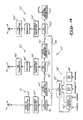
- FIG. 4 Illustrated in Figure 4 is an FM radio frequency broadcast system or network 140 with boosters, which is a still further modification of the FM radio frequency broadcast system or network 10.
- Elements of the FM radio frequency system or network 140 similar in construction and operation to the elements of the radio frequency system or network 10 are designated with the same reference numeral but with a triple prime suffix.
- the FM radio frequency broadcast system or network 140 differs from the FM radio frequency broadcast system or network 10 in that the reference time base signal from the STL receiver 35''' is applied over a separate path to an FM modulating exciter 40a.
- An IF repeater STL receiver-transmitter 60a is located at a relay point between the originating transmitter station 15''' and the booster station 20'''.
- the FM signal received by the IF repeater STL receiver-transmitter 60a from the originating transmitters 45''' is in the range of 88 MHz-108 MHz.
- the IF signal from the STL receiver 70''' is applied to the synchronous FM exciter 75'''.
- the FM exciter 40a is a modification of a conventional FM broadcast exciter and is arranged to accept an external time base reference signal for phase locking the broadcast frequency carrier in the range of 88-108 MHz.
- the external time base reference signal is in the frequency range of 2.5 KHz to 19 KHz and is generated from a conventional stable crystal oscillator, not shown, having a long term stability of a ppm per year.
- the time base reference signal for locking the FM broadcast exciter 40a is generated in the STL receiver 35'''.
- FIG. 5 Illustrated in Figure 5 is the synchronous FM exciter 75 shown in block diagram in Figure 1.
- the synchronous FM exciters 40 and 105 are similar in construction and operation to the synchronous FM exciter 75 and, hence, only the synchronous FM exciter 75 will be described in detail. It follows that the synchronous FM exciters 40', 75', 105', 40'', 75'', 105'', and 75''' are similar in construction and operation to the synchronous FM exciter 75.
- the synchronous FM exciter 75 has applied thereto from the STL receiver 70 an FM signal, which, in the exemplary embodiment, is a 10.7 MHz FM signal modulated by the composite signals for the FM broadcasting including a reference signal of 19 KHz, in the exemplary embodiment.
- the 10.7 MHz FM signal is applied to a conventional FM discriminator 141, which demodulates the 10.7 MHz signal into the reference signal of 19 KHz.
- the 19 KHz reference signal is applied to one input of a conventional phase detector of a phase locked loop circuit 143.
- a suitable reference signal is generated by a conventional voltage controlled crystal oscillator (VCXO) 145 of the phase locked loop circuit 143.
- VCXO voltage controlled crystal oscillator
- One output of the VCXO 145 is applied to a conventional frequency divider network 146 of the phase locked loop circuit 143.
- the output of the frequency divider network 146 which is, in the exemplary embodiment, a 19 KHz reference signal, is applied to the other input of the phase detector 142.
- the phase detector 142 produces in the output thereof an error signal whose amplitude is proportional to the difference in phase between the input signals applied to the phase detector 142.
- the phase error signal is applied to a phase error amplifier 150 of the phase locked loop circuit 143.
- the phase error signal produced in the output of phase error amplifier 150 is applied to the VCXO 145 to compensate for the phase error or difference applied to the inputs of the phase detector 142.
- the VCXO 145 is phase locked to the 19 KHz reference signal contained in the composite signal in the output of the FM discriminator 141.
- the stable reference signal in the output of the VCXO 145 is now phase locked with the reference signal of the composite signal in the output of the FM discriminator 141 and the IF frequency modulated signal sent by the originating broadcast station 15.
- the output of the VCXO 145 is applied to a conventional frequency divider network 154 of a phase locked loop circuit 155.
- the reference signal in the output of the frequency divider network 154 in the exemplary embodiment, is 10 KHz.
- the 10 KHz reference signal of the divider network 154 is applied to one input of a conventional phase detector 165 of a phase locked loop circuit 155.
- a conventional voltage controlled oscillator (VCO) 156 of the phase locked loop circuit 155 applies a frequency to one input of a conventional mixer circuit 160.
- the output frequency of the VCO 156 in the range of 77.3 MHz-97.3 MHz, is the difference between the input frequency from the STL receiver 70 and the broadcast frequency of the re-transmitting transmitter 90.
- Applied to another input of the mixer circuit 160 is the intermediate frequency FM signal from the STL receiver 70.
- the intermediate frequency FM signal of the STL receiver 70 is a 10.7 MHz FM signal.
- the mixer circuit 160 combines by adding the output signal from the VCO 156 and the output signal from the STL receiver 70 and produces in the output thereof the FM broadcast frequency signal in the range of 88 MHz-108 MHz.
- a suitable band-pass filter 161 Connected to the output of the mixer circuit 160 is a suitable band-pass filter 161, which passes FM signals in the frequency range of 88 MHz-108 MHz.
- the output of the band-pass filter 161 is applied to a conventional frequency divider 162 of the phase locked loop circuit 155.
- the frequency divider 162 produces in its output a 10 KHz signal, which is applied to one input of a phase detector 165 of the phase locked loop circuit 155.
- the output of the frequency divider 154 which, in the exemplary embodiment, is 10 KHz, is applied to the other input of the phase detector 165.
- the 10 KHz output signal from the frequency divider 154 is a reference signal.
- the 10 KHz output signal from the frequency divider 162 is a comparison signal.
- the phase detector 165 produces in the output thereof an error signal whose amplitude is proportional to the difference in phase between the input signals applied to the phase detector 165.
- the phase error signal is applied to a phase error amplifier 163 of the phase locked loop circuit 155.
- the phase error signal produced in the output of the phase error amplifier 163 is applied to the VCO 156 to compensate for the phase error or differences of the signals applied to the inputs of the phase detector 165.
- the sum of the frequency of the VCO 156 and the incoming IF signal in the exemplary embodiment, of 10.7 MHz, is phase locked to the 10 KHz reference signal in the output of the frequency divider 162 and is derived from the broadcast frequency by programming the programmable divider 162 in a well-known manner.
- the stable reference signal in the output of the VCXO 145 is now phase locked with the reference signal sampled from the output of the band-pass filter 161, which passes the range of broadcast frequencies.
- the FM broadcast signals in the output of the band-pass filter 161 have been stabilized in frequency and phase as well as modulation level with the IF frequency modulated signals sent by the originating broadcast station 15.
- the phase locked loop circuits 143 and 155 serve to maintain modulation and frequency integrity for the re-transmission station 20.
- the stations 15, 20 and 25 are synchronized to eliminate interference. Heterodyne and noise to the unsynchronized transmitters, phase shifts on the baseband, group delays and inconsistent modulation levels have been obviated to enhance broadcast program quality.
- the FM broadcast output signals of the band-pass filter 161 are applied to a suitable power amplifier 170, which amplifies the power level of the FM broadcast output signals of the band-pass filter 161.
- a suitable band-pass filter 171 Connected to the output of the power amplifier 170 is a suitable band-pass filter 171, which passes FM broadcast signals in the range of 88 MHz to 108 MHz.
- a suitable power amplifer 172 is connected to the band-pass filter 171 and its FM broadcast output signal is applied to the booster 85.
- the FM broadcast output signal of the booster 85 is applied to the re-transmitter 90 for broadcasting the FM signal that has originated from the broadcast studio 30.
- a conventional automatic level control (ALC) circuit 175 is coupled to the output of the power amplifier 172 and applies a compensating control voltage to the power amplifier 172 to automatically maintain power output level applied to the booster 85. Included in the ALC circuit 175 is an adjustable variable resistor 176 for setting a reference voltage applied to the level control circuiting of power amplifier 172 in a well-known manner.
- a synchronous FM exciter 180 Illustrated in Figure 6 is a synchronous FM exciter 180, which is a modification of the synchronous FM exciter 75 shown in Figure 5.
- Components of the synchronous FM exciter 180 similar in construction and operation to the components of the synchronous FM exciter 75 have been designated with the same reference numerals but with a suffix "a".
- the synchronous FM exciter 180 differs from the synchronous FM exciter 75 to the extent that a phase locked loop circuit 185 is interposed between the STL receiver 70 with the mixer 160a.
- the phase locked loop circuit 185 includes a phase detector 186.
- the STL receiver 70 applies the FM intermediate frequency modulated signal having a modulation level of ⁇ f1 in the output thereof to a suitable frequency divider circuit 187 of the phase locked loop circuit 185.
- the output of the frequency divider circuit 187 having a dividing ratio of N4 is applied to one input of the phase detector 186.
- the output of the frequency divider circuit 187 is an FM 5.35 MHz signal having a modulation level of 1 ⁇ 2 ⁇ f1, since N4 is chosen to be 2.
- phase locked loop circuit 185 Also included in the phase locked loop circuit 185 is a suitable voltage controlled oscillator 188, which applies a stable comparison signal to another input of the phase detector 186 through a suitable frequency divider circuit 189 having a dividing ratio of N5.
- the output of VCO 188 is 16.05 MHz and the stable comparison signal applied to the phase detector 186 is a 5.35 MHz having a modulation level of 3/2 ⁇ f1, since N5 is chosen to be 3.
- the phase detector 186 compares the phase of the signals applied to the inputs thereof. If there is a phase difference therebetween, the error or difference therebetween produces a voltage amplitude in the output of the phase detector 186 commensurate with such error or difference.
- the phase difference signal produced in the output of the phase detector 186 is applied to an error correction amplifier 190.
- the output of the error correction amplifier 190 is applied to the voltage controlled oscillator 188 to correct the phase error between the signals applied to the inputs of the phase detector 186.
- the frequency and the modulation characteristics of the VCO 188 may be calculated in the following manner: In this manner, the modulation level of an incoming FM carrier can be modified to a level of modulation acceptable to the succeeding STL receiver.
- the level of modulation of an FM signal applied to a transmitter for re-transmission can be synchronized and stabilized with the level of modulation of an FM radio frequency signal transmitted at an originating transmitter, when the FM intermediate frequency signal is modified to a level of modulation acceptable to the succeeding STL receiver.
Landscapes
- Engineering & Computer Science (AREA)
- Signal Processing (AREA)
- Transmitters (AREA)
- Radio Relay Systems (AREA)
Applications Claiming Priority (1)
| Application Number | Priority Date | Filing Date | Title |
|---|---|---|---|
| US07/326,744 US5046124A (en) | 1989-03-21 | 1989-03-21 | Frequency modulated radio frequency broadcast network employing a synchronous frequency modulated booster system |
Publications (1)
| Publication Number | Publication Date |
|---|---|
| EP0462341A1 true EP0462341A1 (de) | 1991-12-27 |
Family
ID=23273524
Family Applications (1)
| Application Number | Title | Priority Date | Filing Date |
|---|---|---|---|
| EP90306817A Withdrawn EP0462341A1 (de) | 1989-03-21 | 1990-06-21 | Synchronisiertes frequenzmoduliertes Verstärkersystem |
Country Status (2)
| Country | Link |
|---|---|
| US (2) | US5046124A (de) |
| EP (1) | EP0462341A1 (de) |
Cited By (2)
| Publication number | Priority date | Publication date | Assignee | Title |
|---|---|---|---|---|
| FR2688364A1 (fr) * | 1992-03-06 | 1993-09-10 | Telediffusion Fse | Procede et systeme permettant d'obtenir un reseau d'emetteurs fm, notamment monofrequence synchrone. |
| FR2725089A1 (fr) * | 1994-09-22 | 1996-03-29 | Sarl Ingira Ingenierie Radiote | Systeme pour reseaux de radiotelephonie isofrequence permettant la selection et la mise en phase de maniere stable des modulations de leurs relais |
Families Citing this family (11)
| Publication number | Priority date | Publication date | Assignee | Title |
|---|---|---|---|---|
| US5410588A (en) * | 1991-04-03 | 1995-04-25 | Kabushiki Kaisha Toshiba | Mobile radio communications system having a supervising radio transmitting station for transmitting a reference synchronizing signal to a first and second base stations via a radio link |
| CA2066946A1 (en) * | 1991-05-16 | 1992-11-17 | George Philip Vella-Coleiro | Apparatus and method for synchronizing a plurality of remote transmission and receiving stations |
| JPH084235B2 (ja) * | 1993-03-31 | 1996-01-17 | 日本電気株式会社 | 周波数制御装置 |
| US5594937A (en) * | 1994-09-02 | 1997-01-14 | Ghz Equipment Company | System for the transmission and reception of directional radio signals utilizing a gigahertz implosion concept |
| US5651010A (en) * | 1995-03-16 | 1997-07-22 | Bell Atlantic Network Services, Inc. | Simultaneous overlapping broadcasting of digital programs |
| US5970406A (en) * | 1996-12-31 | 1999-10-19 | Airnet Communication Corp. | Translator for time division multiple access wireless system having selective diversity circuits |
| US20050221816A1 (en) * | 2004-03-31 | 2005-10-06 | Hall Thomas M | System for and method of operating a radio station in a broadcast network |
| JP2010283535A (ja) * | 2009-06-03 | 2010-12-16 | Nagaoka Ido Denwa System Kk | 同期放送システム並びに同期放送方法 |
| JP6924678B2 (ja) * | 2017-11-22 | 2021-08-25 | 株式会社日立国際電気 | 伝送システム |
| KR102554868B1 (ko) * | 2021-04-09 | 2023-07-12 | 주식회사 포인투테크놀로지 | 광대역 rf 통신을 구현하기 위한 시스템 및 방법 |
| JP7595863B1 (ja) * | 2024-05-24 | 2024-12-09 | 山口放送株式会社 | Fm放送システム、fm送信装置、及びfm中継装置 |
Citations (3)
| Publication number | Priority date | Publication date | Assignee | Title |
|---|---|---|---|---|
| JPS57190413A (en) * | 1981-05-18 | 1982-11-24 | Matsushita Electric Ind Co Ltd | Receiver |
| EP0127918A1 (de) * | 1983-05-27 | 1984-12-12 | Philips Patentverwaltung GmbH | Fernsehempfänger mit einem Verarbeitungsteil zum Aufbereiten von Stereo-/Zweiton-Signalen |
| US4608699A (en) * | 1982-12-27 | 1986-08-26 | Motorola, Inc. | Simulcast transmission system |
Family Cites Families (18)
| Publication number | Priority date | Publication date | Assignee | Title |
|---|---|---|---|---|
| US2284415A (en) * | 1939-11-29 | 1942-05-26 | Rca Corp | Relay system |
| US2545197A (en) * | 1947-03-27 | 1951-03-13 | Rca Corp | Relay satellite broadcast system |
| NL168973C (nl) * | 1972-11-23 | 1982-05-17 | Philips Nv | Omroepstelsel. |
| US3902019A (en) * | 1974-06-14 | 1975-08-26 | Rockwell International Corp | Fm broadcast exciter apparatus |
| US4117405A (en) * | 1976-11-02 | 1978-09-26 | Louis Martinez | Narrow-band radio communication system |
| US4188582A (en) * | 1978-04-10 | 1980-02-12 | Motorola, Inc. | Simulcast transmission system having phase-locked remote transmitters |
| US4277833A (en) * | 1978-09-05 | 1981-07-07 | Dickey-John Corporation | Planter population monitor |
| US4208630A (en) * | 1978-10-19 | 1980-06-17 | Altran Electronics, Inc. | Narrow band paging or control radio system |
| US4317220A (en) * | 1979-02-05 | 1982-02-23 | Andre Martin | Simulcast transmission system |
| JPS5647131A (en) * | 1979-09-27 | 1981-04-28 | Toyo Commun Equip Co Ltd | Transmitter with phase synchronization system |
| US4322842A (en) * | 1979-10-23 | 1982-03-30 | Altran Electronics | Broadcast system for distribution automation and remote metering |
| US4506383A (en) * | 1980-01-04 | 1985-03-19 | Harris Corporation | Method and apparatus for relaying signals between a ground station and a satellite using a ground relay station |
| US4451930A (en) * | 1982-08-02 | 1984-05-29 | Motorola Inc. | Phase-locked receiver with derived reference frequency |
| SE435438B (sv) * | 1982-12-09 | 1984-09-24 | Ericsson Telefon Ab L M | Forfarande for instellning av radiosendare pa samtidig sendning |
| NL8401101A (nl) * | 1984-04-06 | 1985-11-01 | Philips Nv | Draaggolfsynchroniseersysteem en daarvoor geschikt basisstation. |
| US4710970A (en) * | 1985-09-11 | 1987-12-01 | Tft, Inc. | Method of and apparatus for generating a frequency modulated ultrahigh frequency radio transmission signal |
| US4696052A (en) * | 1985-12-31 | 1987-09-22 | Motorola Inc. | Simulcast transmitter apparatus having automatic synchronization capability |
| US4837853A (en) * | 1987-06-05 | 1989-06-06 | Motorola, Inc. | Dual port FM demodulation in phase locked receivers |
-
1989
- 1989-03-21 US US07/326,744 patent/US5046124A/en not_active Ceased
-
1990
- 1990-06-21 EP EP90306817A patent/EP0462341A1/de not_active Withdrawn
-
1992
- 1992-03-30 US US07/860,690 patent/USRE34499E/en not_active Expired - Lifetime
Patent Citations (3)
| Publication number | Priority date | Publication date | Assignee | Title |
|---|---|---|---|---|
| JPS57190413A (en) * | 1981-05-18 | 1982-11-24 | Matsushita Electric Ind Co Ltd | Receiver |
| US4608699A (en) * | 1982-12-27 | 1986-08-26 | Motorola, Inc. | Simulcast transmission system |
| EP0127918A1 (de) * | 1983-05-27 | 1984-12-12 | Philips Patentverwaltung GmbH | Fernsehempfänger mit einem Verarbeitungsteil zum Aufbereiten von Stereo-/Zweiton-Signalen |
Non-Patent Citations (1)
| Title |
|---|
| PATENT ABSTRACTS OF JAPAN, vol. 7, no. 36 (E-158)[1181], 8th February 1983; & JP-A-57 190 413 (MATSUSHITA) 24-11-1982 * |
Cited By (3)
| Publication number | Priority date | Publication date | Assignee | Title |
|---|---|---|---|---|
| FR2688364A1 (fr) * | 1992-03-06 | 1993-09-10 | Telediffusion Fse | Procede et systeme permettant d'obtenir un reseau d'emetteurs fm, notamment monofrequence synchrone. |
| EP0562896A1 (de) * | 1992-03-06 | 1993-09-29 | Etablissement Public Télédiffusion de France | Übertragungssteuerungsverfahren und -system eines monofregmenten und/oder FM-Sendernetzwerkes mit Überlappungszone |
| FR2725089A1 (fr) * | 1994-09-22 | 1996-03-29 | Sarl Ingira Ingenierie Radiote | Systeme pour reseaux de radiotelephonie isofrequence permettant la selection et la mise en phase de maniere stable des modulations de leurs relais |
Also Published As
| Publication number | Publication date |
|---|---|
| US5046124A (en) | 1991-09-03 |
| USRE34499E (en) | 1994-01-04 |
Similar Documents
| Publication | Publication Date | Title |
|---|---|---|
| US4608699A (en) | Simulcast transmission system | |
| US4117405A (en) | Narrow-band radio communication system | |
| US4901368A (en) | Frequency translation correction scheme for satellite communication system | |
| US4363129A (en) | Method and means of minimizing simulcast distortion in a receiver when using a same-frequency repeater | |
| US7218696B2 (en) | Synchronizing carrier frequencies of co-channel amplitude-modulated broadcast | |
| US5046124A (en) | Frequency modulated radio frequency broadcast network employing a synchronous frequency modulated booster system | |
| US4941150A (en) | Spread spectrum communication system | |
| EP0128210B1 (de) | Verfahren und vorrichtung zum synchronisieren von funküberträgern für synchronfunkausstrahlen | |
| EP0662270B1 (de) | Verfahren zur synchronisierung von funksenderfrequenzen im digitalen hörfunk im gleichwellenbetrieb | |
| US5065450A (en) | Frequency modulated radio frequency broadcast network employing a synchronous frequency modulated booster system | |
| US5127101A (en) | Simulcast auto alignment system | |
| US5046128A (en) | Frequency equalized simulcast broadcasting system and method | |
| US3778716A (en) | Coherent catv transmission system | |
| US3835253A (en) | Television communication system with time delay compensation | |
| US4491969A (en) | Satellite ground station | |
| US4466130A (en) | Two pilot frequency control for communication systems | |
| US5291518A (en) | Link system for radio paging service | |
| US3619782A (en) | Coherent catv transmission system | |
| JP2000151553A (ja) | 信号伝送装置 | |
| CA1193674A (en) | Two pilot frequency control for communication systems | |
| US4571621A (en) | Television transmitter | |
| CA2019851A1 (en) | Frequency modulated radio frequency broadcast network employing a synchronous frequency modulated booster system | |
| US6643518B1 (en) | Method and apparatus for synchronizing telecommunications devices via a transmission network | |
| US6456823B1 (en) | System and method for recovering a pilot tone in a local multipoint distribution system signal | |
| CA1114904A (en) | Narrow band communication system |
Legal Events
| Date | Code | Title | Description |
|---|---|---|---|
| PUAI | Public reference made under article 153(3) epc to a published international application that has entered the european phase |
Free format text: ORIGINAL CODE: 0009012 |
|
| AK | Designated contracting states |
Kind code of ref document: A1 Designated state(s): ES GB IT |
|
| STAA | Information on the status of an ep patent application or granted ep patent |
Free format text: STATUS: THE APPLICATION IS DEEMED TO BE WITHDRAWN |
|
| 18D | Application deemed to be withdrawn |
Effective date: 19920907 |