EP0462394A1 - Verbindungselement, insbesondere Fahrzeugstrebe, und Verfahren zur Herstellung - Google Patents
Verbindungselement, insbesondere Fahrzeugstrebe, und Verfahren zur Herstellung Download PDFInfo
- Publication number
- EP0462394A1 EP0462394A1 EP91107698A EP91107698A EP0462394A1 EP 0462394 A1 EP0462394 A1 EP 0462394A1 EP 91107698 A EP91107698 A EP 91107698A EP 91107698 A EP91107698 A EP 91107698A EP 0462394 A1 EP0462394 A1 EP 0462394A1
- Authority
- EP
- European Patent Office
- Prior art keywords
- tube
- connecting element
- tongues
- element according
- tongue
- Prior art date
- Legal status (The legal status is an assumption and is not a legal conclusion. Google has not performed a legal analysis and makes no representation as to the accuracy of the status listed.)
- Granted
Links
- 238000004519 manufacturing process Methods 0.000 title claims description 9
- 210000002105 tongue Anatomy 0.000 claims abstract description 37
- 239000000463 material Substances 0.000 claims abstract description 31
- 229910000679 solder Inorganic materials 0.000 claims abstract description 8
- 239000011324 bead Substances 0.000 claims abstract description 7
- 238000000034 method Methods 0.000 claims description 17
- XEEYBQQBJWHFJM-UHFFFAOYSA-N Iron Chemical compound [Fe] XEEYBQQBJWHFJM-UHFFFAOYSA-N 0.000 claims description 6
- 239000007769 metal material Substances 0.000 claims description 6
- 239000004033 plastic Substances 0.000 claims description 4
- 229920003023 plastic Polymers 0.000 claims description 4
- 229920001169 thermoplastic Polymers 0.000 claims description 4
- 239000004416 thermosoftening plastic Substances 0.000 claims description 4
- RYGMFSIKBFXOCR-UHFFFAOYSA-N Copper Chemical compound [Cu] RYGMFSIKBFXOCR-UHFFFAOYSA-N 0.000 claims description 3
- RTAQQCXQSZGOHL-UHFFFAOYSA-N Titanium Chemical compound [Ti] RTAQQCXQSZGOHL-UHFFFAOYSA-N 0.000 claims description 3
- 229910045601 alloy Inorganic materials 0.000 claims description 3
- 239000000956 alloy Substances 0.000 claims description 3
- 229910052782 aluminium Inorganic materials 0.000 claims description 3
- XAGFODPZIPBFFR-UHFFFAOYSA-N aluminium Chemical compound [Al] XAGFODPZIPBFFR-UHFFFAOYSA-N 0.000 claims description 3
- 229910052802 copper Inorganic materials 0.000 claims description 3
- 239000010949 copper Substances 0.000 claims description 3
- 238000005553 drilling Methods 0.000 claims description 3
- 229910052742 iron Inorganic materials 0.000 claims description 3
- 239000010936 titanium Substances 0.000 claims description 3
- 229910052719 titanium Inorganic materials 0.000 claims description 3
- 230000007704 transition Effects 0.000 claims description 2
- 229920002430 Fibre-reinforced plastic Polymers 0.000 claims 1
- 239000011151 fibre-reinforced plastic Substances 0.000 claims 1
- 239000002990 reinforced plastic Substances 0.000 claims 1
- 239000007767 bonding agent Substances 0.000 abstract 1
- 230000003014 reinforcing effect Effects 0.000 abstract 1
- 239000007787 solid Substances 0.000 abstract 1
- 238000007493 shaping process Methods 0.000 description 6
- 239000000853 adhesive Substances 0.000 description 3
- 230000001070 adhesive effect Effects 0.000 description 3
- 239000011248 coating agent Substances 0.000 description 3
- 238000000576 coating method Methods 0.000 description 3
- 238000003466 welding Methods 0.000 description 3
- 238000005260 corrosion Methods 0.000 description 2
- 230000007797 corrosion Effects 0.000 description 2
- 238000003754 machining Methods 0.000 description 2
- 229910052751 metal Inorganic materials 0.000 description 2
- 239000002184 metal Substances 0.000 description 2
- 229910000831 Steel Inorganic materials 0.000 description 1
- 238000010276 construction Methods 0.000 description 1
- 230000007423 decrease Effects 0.000 description 1
- 238000000465 moulding Methods 0.000 description 1
- 238000012805 post-processing Methods 0.000 description 1
- 238000007789 sealing Methods 0.000 description 1
- 238000005476 soldering Methods 0.000 description 1
- 239000010959 steel Substances 0.000 description 1
Images

Classifications
-
- B—PERFORMING OPERATIONS; TRANSPORTING
- B21—MECHANICAL METAL-WORKING WITHOUT ESSENTIALLY REMOVING MATERIAL; PUNCHING METAL
- B21D—WORKING OR PROCESSING OF SHEET METAL OR METAL TUBES, RODS OR PROFILES WITHOUT ESSENTIALLY REMOVING MATERIAL; PUNCHING METAL
- B21D53/00—Making other particular articles
- B21D53/84—Making other particular articles other parts for engines, e.g. connecting-rods
-
- B—PERFORMING OPERATIONS; TRANSPORTING
- B21—MECHANICAL METAL-WORKING WITHOUT ESSENTIALLY REMOVING MATERIAL; PUNCHING METAL
- B21J—FORGING; HAMMERING; PRESSING METAL; RIVETING; FORGE FURNACES
- B21J5/00—Methods for forging, hammering, or pressing; Special equipment or accessories therefor
- B21J5/06—Methods for forging, hammering, or pressing; Special equipment or accessories therefor for performing particular operations
- B21J5/063—Friction heat forging
- B21J5/066—Flow drilling
-
- B—PERFORMING OPERATIONS; TRANSPORTING
- B23—MACHINE TOOLS; METAL-WORKING NOT OTHERWISE PROVIDED FOR
- B23P—METAL-WORKING NOT OTHERWISE PROVIDED FOR; COMBINED OPERATIONS; UNIVERSAL MACHINE TOOLS
- B23P15/00—Making specific metal objects by operations not covered by a single other subclass or a group in this subclass
-
- F—MECHANICAL ENGINEERING; LIGHTING; HEATING; WEAPONS; BLASTING
- F16—ENGINEERING ELEMENTS AND UNITS; GENERAL MEASURES FOR PRODUCING AND MAINTAINING EFFECTIVE FUNCTIONING OF MACHINES OR INSTALLATIONS; THERMAL INSULATION IN GENERAL
- F16C—SHAFTS; FLEXIBLE SHAFTS; ELEMENTS OR CRANKSHAFT MECHANISMS; ROTARY BODIES OTHER THAN GEARING ELEMENTS; BEARINGS
- F16C7/00—Connecting-rods or like links pivoted at both ends; Construction of connecting-rod heads
- F16C7/02—Constructions of connecting-rods with constant length
-
- B—PERFORMING OPERATIONS; TRANSPORTING
- B23—MACHINE TOOLS; METAL-WORKING NOT OTHERWISE PROVIDED FOR
- B23P—METAL-WORKING NOT OTHERWISE PROVIDED FOR; COMBINED OPERATIONS; UNIVERSAL MACHINE TOOLS
- B23P2700/00—Indexing scheme relating to the articles being treated, e.g. manufactured, repaired, assembled, connected or other operations covered in the subgroups
- B23P2700/04—Connecting rods
-
- B—PERFORMING OPERATIONS; TRANSPORTING
- B23—MACHINE TOOLS; METAL-WORKING NOT OTHERWISE PROVIDED FOR
- B23P—METAL-WORKING NOT OTHERWISE PROVIDED FOR; COMBINED OPERATIONS; UNIVERSAL MACHINE TOOLS
- B23P2700/00—Indexing scheme relating to the articles being treated, e.g. manufactured, repaired, assembled, connected or other operations covered in the subgroups
- B23P2700/14—Suspension elements of automobile vehicles
-
- B—PERFORMING OPERATIONS; TRANSPORTING
- B60—VEHICLES IN GENERAL
- B60G—VEHICLE SUSPENSION ARRANGEMENTS
- B60G2204/00—Indexing codes related to suspensions per se or to auxiliary parts
- B60G2204/40—Auxiliary suspension parts; Adjustment of suspensions
- B60G2204/422—Links for mounting suspension elements
-
- B—PERFORMING OPERATIONS; TRANSPORTING
- B60—VEHICLES IN GENERAL
- B60G—VEHICLE SUSPENSION ARRANGEMENTS
- B60G2206/00—Indexing codes related to the manufacturing of suspensions: constructional features, the materials used, procedures or tools
- B60G2206/01—Constructional features of suspension elements, e.g. arms, dampers, springs
- B60G2206/10—Constructional features of arms
- B60G2206/11—Constructional features of arms the arm being a radius or track or torque or steering rod or stabiliser end link
-
- B—PERFORMING OPERATIONS; TRANSPORTING
- B60—VEHICLES IN GENERAL
- B60G—VEHICLE SUSPENSION ARRANGEMENTS
- B60G2206/00—Indexing codes related to the manufacturing of suspensions: constructional features, the materials used, procedures or tools
- B60G2206/01—Constructional features of suspension elements, e.g. arms, dampers, springs
- B60G2206/70—Materials used in suspensions
- B60G2206/71—Light weight materials
- B60G2206/7101—Fiber-reinforced plastics [FRP]
-
- B—PERFORMING OPERATIONS; TRANSPORTING
- B60—VEHICLES IN GENERAL
- B60G—VEHICLE SUSPENSION ARRANGEMENTS
- B60G2206/00—Indexing codes related to the manufacturing of suspensions: constructional features, the materials used, procedures or tools
- B60G2206/01—Constructional features of suspension elements, e.g. arms, dampers, springs
- B60G2206/70—Materials used in suspensions
- B60G2206/71—Light weight materials
- B60G2206/7102—Aluminium alloys
-
- B—PERFORMING OPERATIONS; TRANSPORTING
- B60—VEHICLES IN GENERAL
- B60G—VEHICLE SUSPENSION ARRANGEMENTS
- B60G2206/00—Indexing codes related to the manufacturing of suspensions: constructional features, the materials used, procedures or tools
- B60G2206/01—Constructional features of suspension elements, e.g. arms, dampers, springs
- B60G2206/70—Materials used in suspensions
- B60G2206/71—Light weight materials
- B60G2206/7104—Thermoplastics
-
- B—PERFORMING OPERATIONS; TRANSPORTING
- B60—VEHICLES IN GENERAL
- B60G—VEHICLE SUSPENSION ARRANGEMENTS
- B60G2206/00—Indexing codes related to the manufacturing of suspensions: constructional features, the materials used, procedures or tools
- B60G2206/01—Constructional features of suspension elements, e.g. arms, dampers, springs
- B60G2206/70—Materials used in suspensions
- B60G2206/72—Steel
-
- B—PERFORMING OPERATIONS; TRANSPORTING
- B60—VEHICLES IN GENERAL
- B60G—VEHICLE SUSPENSION ARRANGEMENTS
- B60G2206/00—Indexing codes related to the manufacturing of suspensions: constructional features, the materials used, procedures or tools
- B60G2206/01—Constructional features of suspension elements, e.g. arms, dampers, springs
- B60G2206/80—Manufacturing procedures
- B60G2206/81—Shaping
- B60G2206/8103—Shaping by folding or bending
-
- B—PERFORMING OPERATIONS; TRANSPORTING
- B60—VEHICLES IN GENERAL
- B60G—VEHICLE SUSPENSION ARRANGEMENTS
- B60G2206/00—Indexing codes related to the manufacturing of suspensions: constructional features, the materials used, procedures or tools
- B60G2206/01—Constructional features of suspension elements, e.g. arms, dampers, springs
- B60G2206/80—Manufacturing procedures
- B60G2206/82—Joining
- B60G2206/8201—Joining by welding
-
- B—PERFORMING OPERATIONS; TRANSPORTING
- B60—VEHICLES IN GENERAL
- B60G—VEHICLE SUSPENSION ARRANGEMENTS
- B60G2206/00—Indexing codes related to the manufacturing of suspensions: constructional features, the materials used, procedures or tools
- B60G2206/01—Constructional features of suspension elements, e.g. arms, dampers, springs
- B60G2206/80—Manufacturing procedures
- B60G2206/82—Joining
- B60G2206/8208—Joining by hemming or seaming, e.g. by folding of the rim
Definitions
- the present invention relates to a connecting element, in particular a vehicle strut, with eyes arranged at both ends for receiving joints, bearings or fastening elements.
- the invention further relates to a method for its production.
- Fasteners of this type have so far been designed as forged, cast or sheet metal parts. Forged and cast parts are massive due to the manufacturing process and accordingly have a comparatively high weight. The production is complex and expensive. Machining is also necessary.
- the object of the present invention is therefore to develop a connecting element, in particular a vehicle strut, which is light and torsionally rigid and which is also inexpensive to produce. Another object is to provide a method with which such a connecting element can be produced by simple deformation steps, without the use of complicated tools and without complex post-processing.
- the connecting element according to the present invention consists of a tube or a tube-like profile.
- the pipe ends are first flattened, so that the pipe walls taper from the undeformed area and merge into flat tongues towards the ends.
- the eyes are then molded into these tongues by flow drilling.
- the material is not removed, but pressed apart by a rotating bolt. This creates eyes with massive walls that protrude from the tongues like a bulge.
- the walls must ensure a firm hold of the joints, bearings or fasteners to be accommodated. Sufficient wall thickness is required for this. If too little material is available to form the eye walls, for example when using very thin-walled pipes, the following measures can help.
- the outer part of the tongues can be bent back by 180 degrees, so that the material thickness in the eye area corresponds to four times the pipe wall thickness.
- blocks of material can be inserted into the end regions of the tube before flattening.
- the blocks can have any cross section. They should preferably consist of a material that welds firmly to the pipe material under the deformation conditions or when using elevated temperature. The deformation properties should roughly correspond to those of the pipe material.
- a further possibility for providing the material required for working out the eyes is to use tubes whose inside diameter decreases towards the tube ends, with the outside diameter remaining the same. Such tubes are commonly referred to as "butted tubes" and are used, for example, in the manufacture of frames for racing bicycles. The measures listed can also be combined if necessary. In any case, a sufficient amount of material is guaranteed even with light, thin-walled pipes.
- a stiffening bead can be formed in the area of the deformed pipe ends. This is preferably arranged in a fork shape on the outer sides of the tongues. The shaping of the stiffening bead can be carried out simultaneously with the flattening of the pipe ends using a suitably designed tool.
- the tongues opposite each other can be molded in the flattening of the pipe ends so that the tongue planes are rotated against each other at any angle with respect to the pipe axis.
- the pipe itself can be bent as desired. This should preferably be done before machining the pipe ends.
- An improvement in the strength or stability of the connecting element according to the invention can be achieved by coating the inner tube walls with an adhesion-promoting layer, e.g. an adhesive. This results in a firm connection of the tube walls lying against each other in the tongue area. At the same time, unavoidable cavities in this area are sealed, thus effectively preventing crevice corrosion.
- an adhesion-promoting layer e.g. an adhesive
- tubes made of metallic materials are used.
- Materials with good cold formability such as aluminum, copper, titanium, iron (steel) or their alloys, are particularly suitable.
- Welded or soldered pipes can also be used if there are clean weld seams or solder joints and the area of the weld seams or solder joints is deformable to the same extent as the actual pipe material.
- a coating with a solder material matched to the tube material can also be applied to the tube inner walls (at least in the end regions).
- the heat of deformation or the use of elevated temperature during the deformation results in firm soldering or welding of the tube walls in the tongue area. This increases the torsional rigidity of the fastener. At the same time, crevice corrosion is also prevented in this case by filling or sealing the cavities with the solder material.
- tubes made of a plastic material can also be used.
- Thermoplastics that soften under the influence of heat and thus enable easy forming are preferred. At the same time, welding of the flattened pipe walls is guaranteed.
- reinforced, especially fiber-reinforced thermoplastics should be used.
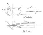
- Fig. 1 shows a partial view of the connecting element before the shaping of the eyes.
- the end of the tube 1 is flattened into a tongue 4.
- an external stiffening bead 6 is arranged on both sides.
- the outer ends 8 of the tongue 4 were punched out round.
- the gap 5 between the tube walls in the area of the tongue 4 can for example be filled with an adhesive or a solder material.
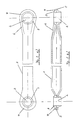
- Fig. 2 shows a possible embodiment of the finished connecting element.
- the eyes 2 were molded into the tongues 4 by flow drilling.
- the eye walls 3 are formed by the material pressed outwards.
- the axes of the eyes 2 run perpendicular to the tongue plane.
- the tongues 4 lying opposite one another are aligned, so the axes of the eyes 2 run parallel to one another.
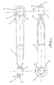
- FIG 3 shows a further embodiment of the connecting element according to the invention.
- the tongues 4 arranged on both sides are rotated relative to one another by an angle of 90 degrees [in relation to the axis of the connecting element].
- the axes of the eyes 2 accordingly run at right angles to one another. The angle can be chosen according to the design requirements.
- the connecting element 4 shows the end region of a further variant of the connecting element in cross section.
- the condition before the shaping of the eyes is shown.
- the outer part of the tongue 4 is bent back by 180 degrees, so that the material thickness here corresponds approximately to four times the wall thickness of the tube 1. This ensures that a sufficient amount of material is available for molding the eyes, even with thin-walled tubes.
- the connecting element according to the invention is light and stable. It is made from an inexpensive mass product (pipe). According to the proposed manufacturing process, only simple forming steps are necessary. The tool costs are minimal. The process is accordingly simple and inexpensive.
Landscapes
- Engineering & Computer Science (AREA)
- Mechanical Engineering (AREA)
- General Engineering & Computer Science (AREA)
- Mutual Connection Of Rods And Tubes (AREA)
- Body Structure For Vehicles (AREA)
- Vehicle Body Suspensions (AREA)
Abstract
Description
- Die vorliegende Erfindung betrifft ein Verbindungselement, insbesondere eine Fahrzeugstrebe, mit beidends angeordneten Augen zur Aufnahme von Gelenken, Lagern oder Befestigungselementen. Die Erfindung betrifft weiterhin ein Verfahren zu dessen Herstellung.
- Verbindungselemente dieser Art werden bisher als Schmiede-, Guß- oder Blechformteile ausgeführt. Dabei sind Schmiede- und Gußteile bedingt durch das Herstellungsverfahren massiv und weisen dementsprechend ein vergleichsweise hohes Gewicht auf. Die Herstellung ist aufwendig und kostspielig. Zudem ist eine spanende Nachbearbeitung notwendig.
- Im Fahrzeugbau, bei dem derartige Verbindungselemente vornehmlich als Streben Verwendung finden sind insbesondere Gewichtseinsparungen sowie einfache, kostengünstige Herstellungsverfahren von besonderer Bedeutung. Gleichzeitig müssen hohe Festigkeitsanforderungen erfüllt werden. Verbindungselemente aus Blechformteilen sind zwar leicht, die Herstellung erfordert aber hohe Werkzeugkosten und zusätzliche Schweißarbeiten.
- Aufgabe der vorliegenden Erfindung ist es daher, ein Verbindungselement, insbesondere eine Fahrzeugstrebe, zu entwickeln, das leicht und verwindungssteif ist und zudem kostengünstig herstellbar ist. Eine weitere Aufgabe ist es, ein Verfahren anzugeben, mit dem ein derartiges Verbindungselement durch einfache Verformungsschritte hergestellt werden kann, ohne Anwendung komplizierter Werkzeuge und ohne eine aufwendige Nachbearbeitung.
- Diese Aufgabe wird erfindungsgemäß gelöst durch die in den Ansprüchen angegebenen Merkmale.
Das Verbindungselement gemäß der vorliegenden Erfindung besteht aus einem Rohr bzw. einem rohrähnlichen Profil. Die Rohrenden werden zunächst abgeplattet, so daß die Rohrwandungen vom unverformten Bereich aus spitz aufeinanderzulaufen und zu den Enden hin in flache Zungen übergehen. In diese Zungen werden anschliessend die Augen durch Fließbohren eingeformt. Dabei wird das Material nicht entfernt, sondern durch einen sich drehenden Bolzen auseinandergepreßt. Dadurch entstehen Augen mit massiven Wandungen, die wulstartig aus den Zungen herausragen. Die Wandungen müssen einen festen Halt der aufzunehmenden Gelenke, Lager oder Befestigungselemente gewährleisten. Dazu ist eine ausreichende Wandstärke erforderlich. Steht zur Ausbildung der Augenwandungen zu wenig Material zur Verfügung, z.B. beim Einsatz sehr dünnwandiger Rohre, können die folgenden Maßnahmen Abhilfe schaffen. - Zum einen kann nach der Abplattung der Rohrenden der äußere Teil der Zungen um 180 Grad zurückgebogen werden, so daß die Materialdicke im Augenbereich der vierfachen Rohrwandstärke entspricht. Zum anderen können vor der Abplattung Materialblöcke in die Endbereiche des Rohres eingelegt werden. Die Blöcke können einen beliebigen Querschnitt aufweisen. Sie sollten vorzugsweise aus einem Material bestehen, das unter den Verformungsbedingungen bzw. bei Anwendung erhöhter Temperatur mit dem Rohrmaterial fest verschweißt. Die Verformungseigenschaften sollten dabei denen des Rohrmaterials in etwa entsprechen. Eine weitere Möglichkeit zur Bereitstellung des für die Herausarbeitung der Augen erforderlichen Materials ist die Verwendung von Rohren, deren Innendurchmesser zu den Rohrenden hin abnimmt, bei gleichbleibendem Außendurchmesser. Derartige Rohre werden handelsüblich als "butted tubes" bezeichnet und finden z.B. Verwendung bei der Herstellung von Rahmen für Rennräder. Die angeführten Maßnahmen können falls erforderlich auch kombiniert werden. In jedem Fall wird auch bei leichten, dünnwandigen Rohren eine ausreichende Materialmenge gewährleistet.
- Zur Erhöhung der Verwindungssteifigkeit des Verbindungselementes kann im Bereich der verformten Rohrenden eine Versteifungswulst eingeformt werden. Diese ist vorzugsweise gabelförmig an den Außenseiten der Zungen angeordnet. Die Einformung der Versteifungswulst kann durch ein entsprechend ausgebildetes Werkzeug gleichzeitig mit der Abplattung der Rohrenden erfolgen.
- Entsprechend den Konstruktionsanforderungen können die einander gegenüberliegenden Zungen bei der Abplattung der Rohrenden so eingeformt werden, daß die Zungenebenen in einem beliebigen Winkel, bezogen auf die Rohrachse, gegeneinander gedreht sind. Falls erforderlich, kann auch das Rohr selbst beliebig gebogen werden. Dies sollte vorzugsweise vor der Bearbeitung der Rohrenden erfolgen.
- Zur Erleichterung der Formgebung und um das Auftreten von Rissen auszuschließen kann es je nach Umformbarkeit der eingesetzten Werkstoffe vorteilhaft sein, die Verformungsschritte bei erhöhten Temperaturen durchzuführen.
- Eine Verbesserung der Festigkeit bzw. Stabilität des erfindungsgemäßen Verbindngselementes kann erreicht werden durch Beschichtung der Rohrinnenwandungen mit einer haftvermittelnden Schicht, z.B. einem Klebstoff. Diese bewirkt eine feste Verbindung der im Zungenbereich aneinanderliegenden Rohrwandungen. Gleichzeitig werden unvermeidbare Hohlräume in diesem Bereich abgedichtet und so eine Spaltkorrosion wirksam verhindert.
- In bevorzugter Ausführungsform des erfindungsgemäßen Verbindungselementes werden Rohre aus metallischen Werkstoffen verwendet. Besonders geeignet sind dabei Werkstoffe mit guter Kaltumformbarkeit, wie z.B. Aluminium, Kupfer, Titan, Eisen (Stahl) oder deren Legierungen. Auch geschweißte oder gelötete Rohre können eingesetzt werden, wenn saubere Schweißnähte bzw. Lötstellen vorliegen und der Bereich der Schweißnähte bzw. Lötstellen in gleichem Maße verformbar ist wie das eigentliche Rohrmaterial.
- Bei Wahl eines metallischen Werkstoffes kann anstelle einer Klebstoffbeschichtung auch eine Beschichtung mit einem auf den Rohrwerkstoff abgestimmten Lotmaterial auf die Rohrinnenwandungen (zumindest in den Endbereichen) aufgebracht werden. Durch die Verformungswärme oder auch durch Anwendung erhöhter Temperatur bei der Verformung erfolgt eine feste Verlötung bzw. Verschweißung der Rohrwandungen im Zungenbereich. Dadurch wird die Verwindungssteifigkeit des Befestigungselementes erhöht. Gleichzeitig wird auch in diesem Fall eine Spaltkorrosion verhindert durch Ausfüllen bzw. Abdichten der Hohlräume mit dem Lotmaterial.
- In Anwendungsfällen mit geringeren Anforderungen an die Festigkeit bzw. Stabilität des Verbindungselementes können auch Rohre aus einem Kunststoffmaterial verwendet werden. Vorzuziehen sind hier Thermoplaste, die unter Wärmeeinwirkung erweichen und so eine leichte Umformung ermöglichen. Gleichzeitig ist eine Verschweißung der abgeplatteten Rohrwandungen gewährleistet. Bei höheren Festigkeitsanforderungen sollten verstärkte, insbesondere faserverstärkte Thermoplaste eingesetzt werden.
- Nachfolgend wird die Erfindung anhand von Skizzen beispielhaft erläutert.
Es zeigen: - Fig. 1:
- Teilansicht des Verbindungselementes vor der Einformung der Augen [a) Aufsicht, b) Querschnitt]
- Fig. 2:
- Verbindungselement mit parallelem Verlauf der Augenachsen [a) Aufsicht, b) Querschnitt]
- Fig. 3:
- Verbindungselement mit rechtwinkligem Verlauf der Augenachsen [Teilschnitte]
- Fig. 4:
- Verbindungselement mit abgewinkelter Zunge vor der Einformung der Augen [Teilansicht im Querschnitt]
- Fig. 1 zeigt eine Teilansicht des Verbindungselementes vor der Einformung der Augen. Das Ende des Rohres 1 ist zu einer Zunge 4 abgeplattet. Im Übergang vom unverformten Bereich des Rohres 1 zur Zunge 4 ist beidseitig eine außenliegende Versteifungswulst 6 angeordnet. Die äußeren Enden 8 der Zunge 4 wurden rund abgestanzt. Der Spalt 5 zwischen den Rohrwandungen im Bereich der Zunge 4 kann beispielsweise mit einem Klebstoff oder einem Lotmaterial gefüllt sein.
- Fig. 2 zeigt eine mögliche Ausführungsform des fertigen Verbindungselementes. Die Augen 2 wurden durch Fließbohren in die Zungen 4 eingeformt. Die Augenwandungen 3 werden gebildet durch das dabei nach außen gepreßte Material. Die Achsen der Augen 2 verlaufen senkrecht zur Zungenebene. Die einander gegenüberliegenden Zungen 4 sind fluchtend angeordnet, dementsprechend verlaufen die Achsen der Augen 2 parallel zueinander.
- Fig. 3 zeigt eine weiter Ausführungsform des erfindungsgemäßen Verbindungselementes. Hier sind die beidends angeordneten Zungen 4 um einen Winkel von 90 Grad gegeneinander gedreht [bezogen auf die Achse des Verbindungselementes]. Die Achsen der Augen 2 verlaufen dementsprechend rechtwinklig zueinander. Der Winkel kann entsprechend den Konstruktionsanforderungen beliebig gewählt werden.
- Fig. 4 zeigt den Endbereich einer weiteren Variante des Verbindungselementes im Querschnitt. Dargestellt ist der Zustand vor der Einformung der Augen. In diesem Fall ist der äußere Teil der Zunge 4 um 180 Grad zurückgebogen, so daß die Materialdicke hier etwa der vierfachen Wandstärke des Rohres 1 entspricht. Auf diese Weise wird gewährleistet, daß auch bei dünnwandigen Rohren eine ausreichende Materialmenge für die Einformung der Augen zur Verfügung steht.
- Das erfindungsgemäße Verbindungselement ist leicht und stabil. Es wird aus einem preiswerten Massenprodukt (Rohr) hergestellt. Nach dem vorgeschlagenen Herstellverfahren sind ausschließlich einfache Umformungsschritte notwendig. Die Werkzeugkosten sind minimal. Das Verfahren ist dementsprechend einfach und kostengünstig.
Claims (27)
- Verbindungselement, insbesondere Fahrzeugstrebe, mit beidends angeordneten Augen zur Aufnahme von Gelenken, Lagern oder Befestigungselementen, dadurch gekennzeichnet, daß das Verbindungselement aus einem Rohr (1) besteht, an dessen Enden die Rohrwandungen spitz zulaufen und in Zungen (4) enden, wobei die Zungen (4) mit je einem Auge (2) versehen sind, dessen Achse senkrecht zur Zungenebene verläuft.
- Verbindungselement nach Anspruch 1, dadurch gekennzeichnet, daß die äußeren Enden der Zungen (4) abgerundet sind.
- Verbindungselement nach einem der vorhergehenden Ansprüche, dadurch gekennzeichnet, daß im Übergang zwischen dem Rohr (1) und der Zunge (4) beidseitig eine außenliegende gabelförmige Versteifungswulst (6) angeordnet ist.
- Verbindungselement nach einem der vorhergehenden Ansprüche, dadurch gekennzeichnet, daß die Zungen (4) so angeordnet sind, daß die Zungenebenen achsial in einem beliebigen Winkel gegeneinander gedreht sind.
- Verbindungselement nach einem der vorhergehenden Ansprüche, dadurch gekennzeichnet, daß das Rohr (1) gebogen ist.
- Verbindungselement nach einem der vorhergehenden Ansprüche, dadurch gekennzeichnet, daß ein Spalt (5) zwischen den Rohrwandungen im Bereich der Zungen (4) mit einer haftvermittelnden Schicht ausgefüllt ist.
- Verbindungselement nach einem der vorhergehenden Ansprüche, dadurch gekennzeichnet, daß der äußere Teil der Zunge (4) um 180 ° abgewinkelt ist.
- Verbindungselement nach einem der vorhergehenden Ansprüche, dadurch gekennzeichnet, daß das Rohr (1) aus einem metallischen Werkstoff besteht.
- Verbindungselement nach Anspruch 8, dadurch gekennzeichnet, daß der metallische Werkstoff ausgewählt ist aus der Gruppe Aluminium, Kupfer, Titan, Eisen oder deren Legierungen.
- Verbindungselement nach einem der Ansprüche 8 oder 9, dadurch gekennzeichnet, daß der Spalt (5) zwischen den Rohrwandungen im Bereich der Zungen (4) mit einem Lotmaterial bzw. einem mit den Rohrwerkstoffen verschweißbaren Material ausgefüllt ist.
- Verbindungselement nach einem der Ansprüche 1 bis 7, dadurch gekennzeichnet, daß das Rohr aus einem Kunststoff, vorzugsweise einem Thermoplast, besteht.
- Verbindungselement nach Anspruch 11, dadurch gekennzeichnet, daß der Kunststoff verstärkt, vorzugsweise faserverstärkt ist.
- Verfahren zur Herstellung eines Verbindungselementes, insbesondere einer Fahrzeugstrebe, mit beidends angeordneten Augen zur Aufnahme von Gelenken, Lagern oder Befestigungselementen, dadurch gekennzeichnet, daß das Verbindungselement aus einem Rohr (1) besteht, dessen Enden zu Zungen (4) abgeplattet werden, und in jede der Zungen (4) ein Auge (2) durch Fließbohren eingeformt wird.
- Verfahren nach Anspruch 13, dadurch gekennzeichnet, daß die äußeren Ecken (8) der Zungen (4) rund abgestanzt werden.
- Verfahren nach Anspruch 13 oder 14, dadurch gekennzeichnet, daß bei der Abplattung der Rohrenden beidseitig eine außenliegende Versteifungswulst (6) angeformt wird, die sich vom unverformten Bereich des Rohres (1) bis in die Zunge (4) erstreckt.
- Verfahren nach einem der Ansprüche 13 bis 15, dadurch gekennzeichnet, daß die Abplattung der Rohrenden in einem beliebigen Winkel achsial gegeneinander gedreht durchgeführt wird.
- Verfahren nach einem der Ansprüche 13 bis 16, dadurch gekennzeichnet, daß das Rohr (1) vor der Abplattung der Enden gebogen wird.
- Verfahren nach einem der Ansprüche 13 bis 17, dadurch gekennzeichnet, daß die Verformungsschritte bei erhöhter Temperatur durchgeführt werden.
- Verfahren nach einem der Ansprüche 13 bis 18, dadurch gekennzeichnet, daß die Rohrenden vor der Abplattung innenseitig mit einer haftvermittelnden Schicht versehen werden.
- Verfahren nach einem der Ansprüche 13 bis 19, dadurch gekennzeichnet, daß der äußere Teil der Zunge (4) vor der Einformung der Augen um 180 ° zurückgebogen wird.
- Verfahren nach einem der Ansprüche 13 bis 20, dadurch gekennzeichnet, daß vor der Abplattung in die Rohrenden ein Material eingelegt wird, das mit dem Rohrwerkstoff verschweißbar ist.
- Verfahren nach einem der Ansprüche 13 bis 21, dadurch gekennzeichnet, daß ein Rohr verwendet wird, dessen Wandstärke bei gleichbleibendem Außendurchmesser zu den Enden hin zunimmt.
- Verfahren nach einem der Ansprüche 13 bis 22, dadurch gekennzeichnet, daß als Rohrmaterial ein metallischer Werkstoff angewendet wird.
- Verfahren nach einem der Ansprüche 13 bis 23, dadurch gekennzeichnet, daß als metallischer Werkstoff Aluminium, Kupfer, Titan, Eisen oder deren Legierungen eingesetzt werden.
- Verfahren nach Ansprüche 23 oder Anspruch 24, dadurch gekennzeichnet, daß die Innenseiten der Rohrenden vor der Abplattung mit einem Lotmaterial beschichtet werden.
- Verfahren nach einem der Ansprüche 13 bis 22, dadurch gekennzeichnet, daß als Rohrmaterial ein Kunststoff, vorzugsweise ein Thermoplast, verwendet wird.
- Verfahren nach Ansprüche 26, dadurch gekennzeichnet, daß als Rohrmaterial ein verstärkter Kunststoff, vorzugsweise ein faserverstärkter Kunststoff eingesetzt wird.
Applications Claiming Priority (2)
| Application Number | Priority Date | Filing Date | Title |
|---|---|---|---|
| DE4019270A DE4019270A1 (de) | 1990-06-16 | 1990-06-16 | Verbindungselement, insbesondere fahrzeugstrebe, und verfahren zur herstellung |
| DE4019270 | 1990-06-16 |
Publications (2)
| Publication Number | Publication Date |
|---|---|
| EP0462394A1 true EP0462394A1 (de) | 1991-12-27 |
| EP0462394B1 EP0462394B1 (de) | 1995-03-08 |
Family
ID=6408532
Family Applications (1)
| Application Number | Title | Priority Date | Filing Date |
|---|---|---|---|
| EP91107698A Expired - Lifetime EP0462394B1 (de) | 1990-06-16 | 1991-05-13 | Verbindungselement, insbesondere Fahrzeugstrebe, und Verfahren zur Herstellung |
Country Status (3)
| Country | Link |
|---|---|
| EP (1) | EP0462394B1 (de) |
| AT (1) | ATE119633T1 (de) |
| DE (2) | DE4019270A1 (de) |
Cited By (8)
| Publication number | Priority date | Publication date | Assignee | Title |
|---|---|---|---|---|
| WO1998057764A1 (fr) * | 1997-06-18 | 1998-12-23 | Vallourec Composants Automobiles Vitry | Procede pour la liaison de deux pieces tubulaires l'une a l'autre |
| WO1999028638A1 (de) * | 1997-12-02 | 1999-06-10 | Daimler-Benz Aktiengesellschaft | Pleuelstange für eine hubkolbenmaschine sowie verfahren zu ihrer herstellung |
| FR2777846A1 (fr) * | 1998-04-23 | 1999-10-29 | Jidosha Denki Kogyo Kk | Tige de liaison articulee pour un dispositif d'essuie-glace |
| WO2014019787A1 (de) * | 2012-08-02 | 2014-02-06 | Zf Friedrichshafen Ag | Fahrwerkstrebe aus organoblech |
| NL2009479C2 (nl) * | 2012-09-18 | 2014-03-19 | Valk Systemen Bvvd | Bediening van een luchtraam in de kassenbouw. |
| CN107363479A (zh) * | 2017-07-20 | 2017-11-21 | 江苏省常熟环通实业有限公司 | 一种健身器材用异形焊管的制备方法 |
| EP3213944A4 (de) * | 2014-10-28 | 2018-06-27 | Nhk Spring Co., Ltd. | Verbindungsarmelement |
| CN113399815A (zh) * | 2021-06-24 | 2021-09-17 | 内蒙古工业大学 | 一种流体导通支管与干管卷边焊接设备 |
Families Citing this family (6)
| Publication number | Priority date | Publication date | Assignee | Title |
|---|---|---|---|---|
| DE4300642C1 (de) * | 1993-01-13 | 1993-11-25 | Vaw Ver Aluminium Werke Ag | Verfahren zur Herstellung von Verbindungselementen mit Augen |
| DE4343841C3 (de) * | 1993-12-22 | 2000-09-14 | Daimler Chrysler Ag | Verfahren zum Herstellen eines Achslenkers |
| DE10301915A1 (de) * | 2003-01-17 | 2004-08-05 | Voith Turbo Gmbh & Co. Kg | Verfahren zur Herstellung eines Tragelementes für einen Rahmen aus einem Basiselement |
| DE102009031763A1 (de) * | 2009-07-06 | 2011-01-13 | Aktiebolaget Skf | Pleuel und Verfahren zu seiner Herstellung |
| DE102010049565A1 (de) * | 2010-10-25 | 2012-04-26 | Daimler Ag | Drehstabfeder für ein Kraftfahrzeug |
| DE102013205440B4 (de) | 2013-03-27 | 2025-06-12 | Bayerische Motoren Werke Aktiengesellschaft | Verfahren zur Herstellung eines Faserverbundbauteils mit verstärktem Anbindungsabschnitt zur lokalen Krafteinleitung |
Citations (8)
| Publication number | Priority date | Publication date | Assignee | Title |
|---|---|---|---|---|
| GB129926A (en) * | 1919-01-07 | 1919-07-24 | Alfred Angus Scott | Improvements in Struts or Ties. |
| FR494623A (fr) * | 1916-12-18 | 1919-09-13 | Frederic Schaefer | Bielle perfectionnée |
| FR1531619A (fr) * | 1967-05-24 | 1968-07-05 | Procédé de fabrication de bielles tubulaires | |
| FR2077485A1 (de) * | 1970-01-22 | 1971-10-29 | Creuzet Robert | |
| FR2385935A1 (fr) * | 1977-04-01 | 1978-10-27 | Aerospatiale | Procede permettant la realisation d'un embout fixe pour une bielle de commande, et bielle ainsi obtenue |
| EP0013648A1 (de) * | 1979-01-15 | 1980-07-23 | AEROSPATIALE Société Nationale Industrielle | Verfahren zur Herstellung einer Pleuelstange oder einer Treibstange |
| GB2053766A (en) * | 1979-07-24 | 1981-02-11 | Fulmer Res Inst Ltd | Improvements in or relating to mounting connectors on elongate members |
| GB2165912A (en) * | 1984-10-11 | 1986-04-23 | Trico Pty Ltd | Link |
-
1990
- 1990-06-16 DE DE4019270A patent/DE4019270A1/de not_active Withdrawn
-
1991
- 1991-05-13 DE DE59104844T patent/DE59104844D1/de not_active Expired - Fee Related
- 1991-05-13 EP EP91107698A patent/EP0462394B1/de not_active Expired - Lifetime
- 1991-05-13 AT AT91107698T patent/ATE119633T1/de not_active IP Right Cessation
Patent Citations (8)
| Publication number | Priority date | Publication date | Assignee | Title |
|---|---|---|---|---|
| FR494623A (fr) * | 1916-12-18 | 1919-09-13 | Frederic Schaefer | Bielle perfectionnée |
| GB129926A (en) * | 1919-01-07 | 1919-07-24 | Alfred Angus Scott | Improvements in Struts or Ties. |
| FR1531619A (fr) * | 1967-05-24 | 1968-07-05 | Procédé de fabrication de bielles tubulaires | |
| FR2077485A1 (de) * | 1970-01-22 | 1971-10-29 | Creuzet Robert | |
| FR2385935A1 (fr) * | 1977-04-01 | 1978-10-27 | Aerospatiale | Procede permettant la realisation d'un embout fixe pour une bielle de commande, et bielle ainsi obtenue |
| EP0013648A1 (de) * | 1979-01-15 | 1980-07-23 | AEROSPATIALE Société Nationale Industrielle | Verfahren zur Herstellung einer Pleuelstange oder einer Treibstange |
| GB2053766A (en) * | 1979-07-24 | 1981-02-11 | Fulmer Res Inst Ltd | Improvements in or relating to mounting connectors on elongate members |
| GB2165912A (en) * | 1984-10-11 | 1986-04-23 | Trico Pty Ltd | Link |
Non-Patent Citations (2)
| Title |
|---|
| PATENT ABSTRACTS OF JAPAN, Band 9, Nr. 179 (M-399)[1902], 24. Juli 1985; & JP-A-60 49 115 (TOYOTA JIDOSHA K.K.) 18-03-1985 * |
| PATENT ABSTRACTS OF JAPAN, Band 9, Nr. 215 (M-409)[1938], 3. September 1985; & JP-A-60 76 409 (TOYOTA JIDOSHA K.K.) 30-04-1985 * |
Cited By (11)
| Publication number | Priority date | Publication date | Assignee | Title |
|---|---|---|---|---|
| WO1998057764A1 (fr) * | 1997-06-18 | 1998-12-23 | Vallourec Composants Automobiles Vitry | Procede pour la liaison de deux pieces tubulaires l'une a l'autre |
| FR2764827A1 (fr) * | 1997-06-18 | 1998-12-24 | Vallourec Vitry | Procede pour la liaison de deux pieces tubulaires l'une a l'autre, ensemble mecanique correspondant, et application, notamment aux bras de suspension pour vehicule automobile |
| US6250657B1 (en) | 1997-06-18 | 2001-06-26 | Vallourec Composants Automobiles | Method for mutually connecting two tubular parts |
| WO1999028638A1 (de) * | 1997-12-02 | 1999-06-10 | Daimler-Benz Aktiengesellschaft | Pleuelstange für eine hubkolbenmaschine sowie verfahren zu ihrer herstellung |
| FR2777846A1 (fr) * | 1998-04-23 | 1999-10-29 | Jidosha Denki Kogyo Kk | Tige de liaison articulee pour un dispositif d'essuie-glace |
| WO2014019787A1 (de) * | 2012-08-02 | 2014-02-06 | Zf Friedrichshafen Ag | Fahrwerkstrebe aus organoblech |
| NL2009479C2 (nl) * | 2012-09-18 | 2014-03-19 | Valk Systemen Bvvd | Bediening van een luchtraam in de kassenbouw. |
| EP3213944A4 (de) * | 2014-10-28 | 2018-06-27 | Nhk Spring Co., Ltd. | Verbindungsarmelement |
| US10220666B2 (en) | 2014-10-28 | 2019-03-05 | Nhk Spring Co., Ltd. | Link arm member |
| CN107363479A (zh) * | 2017-07-20 | 2017-11-21 | 江苏省常熟环通实业有限公司 | 一种健身器材用异形焊管的制备方法 |
| CN113399815A (zh) * | 2021-06-24 | 2021-09-17 | 内蒙古工业大学 | 一种流体导通支管与干管卷边焊接设备 |
Also Published As
| Publication number | Publication date |
|---|---|
| DE59104844D1 (de) | 1995-04-13 |
| DE4019270A1 (de) | 1991-12-19 |
| ATE119633T1 (de) | 1995-03-15 |
| EP0462394B1 (de) | 1995-03-08 |
Similar Documents
| Publication | Publication Date | Title |
|---|---|---|
| EP0775884B1 (de) | Wärmetauscher und ein Verfahren zur Herstellung eines Wärmetauschers | |
| EP0462394B1 (de) | Verbindungselement, insbesondere Fahrzeugstrebe, und Verfahren zur Herstellung | |
| DE69219333T2 (de) | Verfahren zum verbinden von verzinkten aluminiumbestandteilen | |
| DE60226336T2 (de) | Verfahren zum innenhochdruckumformen von gegenständen und damit hergestellter gegenstand | |
| DE102008020467A1 (de) | Verfahren zur Herstellung eines Hilfsrahmens, eines Kraftfahrzeugs sowie Hilfsrahmen eines Kraftfahrzeugs | |
| DE2417640A1 (de) | Rohranschlussverbindung | |
| EP0936011A1 (de) | Verfahren zum Verbinden von wenigstens zwei Bauteilen | |
| DE3523921A1 (de) | Verbundprofil und verfahren zu seiner herstellung | |
| DE4120844C1 (de) | ||
| EP0522282B1 (de) | Verbindung von Hohlteilen sowie Verfahren zu ihrer Herstellung | |
| DE102014101979B3 (de) | Verbindungsanordnung sowie Verfahren zur Herstellung einer Verbindungsanordnung und Kraftfahrzeugbauteil | |
| DE9006777U1 (de) | Verbindungselement, insbesondere Fahrzeugstrebe | |
| DE4228238A1 (de) | Fachwerk mit Hohlteilen, Verfahren zu seiner Herstellung und seine Verwendung | |
| DE102005010086B4 (de) | Durch einen Hydroforming-Prozess hergestellte überlappende Verbindung und Verfahren zum Verbinden rohrförmiger Elemente | |
| DE102015100261B4 (de) | Träger für ein Kraftfahrzeug und Herstellungsverfahren für einen Träger für ein Kraftfahrzeug | |
| DE19738948C2 (de) | Verbindungsbauteil für eine Schweißkonstruktion | |
| EP0823296A2 (de) | Verfahren zur Herstellung von korrosionsbeständigen Wärme-übertragern | |
| EP0900604A1 (de) | Umformbares, bereits vorgeformtes, dünnwandiges Halbfabrikat aus insbesondere Metall | |
| WO2012000572A1 (de) | Verbindungsanordnung eines aus einem metallischen faserverstärker aufweisenden verbundbauteils mit einem weiteren bauteil; verfahren zu deren herstellung | |
| EP1556185B1 (de) | Verfahren zur herstellung eines spurstangengehäuses | |
| EP0305462B1 (de) | Vorrichtung zum verschweissen rohrförmiger kunststoffteile | |
| EP0822025A1 (de) | Verfahren zur Herstellung von korrosionsbeständigen Wärmeübertragern | |
| DE102007035014B4 (de) | Verfahren zum Herstellen einer Fügeverbindung | |
| DE4343841C3 (de) | Verfahren zum Herstellen eines Achslenkers | |
| DE102010031890B3 (de) | Verfahren zum Herstellen einer stoffschlüssigen Verbindung und Hohlprofilverbindung |
Legal Events
| Date | Code | Title | Description |
|---|---|---|---|
| PUAI | Public reference made under article 153(3) epc to a published international application that has entered the european phase |
Free format text: ORIGINAL CODE: 0009012 |
|
| AK | Designated contracting states |
Kind code of ref document: A1 Designated state(s): AT BE CH DE ES FR GB IT LI NL SE |
|
| 17P | Request for examination filed |
Effective date: 19920604 |
|
| RAP1 | Party data changed (applicant data changed or rights of an application transferred) |
Owner name: VAW ALUMINIUM AG |
|
| 17Q | First examination report despatched |
Effective date: 19930913 |
|
| GRAA | (expected) grant |
Free format text: ORIGINAL CODE: 0009210 |
|
| AK | Designated contracting states |
Kind code of ref document: B1 Designated state(s): AT BE CH DE ES FR GB IT LI NL SE |
|
| PG25 | Lapsed in a contracting state [announced via postgrant information from national office to epo] |
Ref country code: IT Free format text: LAPSE BECAUSE OF FAILURE TO SUBMIT A TRANSLATION OF THE DESCRIPTION OR TO PAY THE FEE WITHIN THE PRE;WARNING: LAPSES OF ITALIAN PATENTS WITH EFFECTIVE DATE BEFORE 2007 MAY HAVE OCCURRED AT ANY TIME BEFORE 2007. THE CORRECT EFFECTIVE DATE MAY BE DIFFERENT FROM THE ONE RECORDED.SCRIBED TIME-LIMIT Effective date: 19950308 Ref country code: GB Effective date: 19950308 Ref country code: FR Effective date: 19950308 Ref country code: NL Free format text: LAPSE BECAUSE OF NON-PAYMENT OF DUE FEES Effective date: 19950308 Ref country code: ES Free format text: THE PATENT HAS BEEN ANNULLED BY A DECISION OF A NATIONAL AUTHORITY Effective date: 19950308 Ref country code: BE Effective date: 19950308 |
|
| REF | Corresponds to: |
Ref document number: 119633 Country of ref document: AT Date of ref document: 19950315 Kind code of ref document: T |
|
| REF | Corresponds to: |
Ref document number: 59104844 Country of ref document: DE Date of ref document: 19950413 |
|
| PG25 | Lapsed in a contracting state [announced via postgrant information from national office to epo] |
Ref country code: AT Effective date: 19950513 |
|
| PG25 | Lapsed in a contracting state [announced via postgrant information from national office to epo] |
Ref country code: LI Effective date: 19950531 Ref country code: CH Effective date: 19950531 |
|
| PG25 | Lapsed in a contracting state [announced via postgrant information from national office to epo] |
Ref country code: SE Effective date: 19950608 |
|
| EN | Fr: translation not filed | ||
| NLV1 | Nl: lapsed or annulled due to failure to fulfill the requirements of art. 29p and 29m of the patents act | ||
| GBV | Gb: ep patent (uk) treated as always having been void in accordance with gb section 77(7)/1977 [no translation filed] |
Effective date: 19950308 |
|
| PLBE | No opposition filed within time limit |
Free format text: ORIGINAL CODE: 0009261 |
|
| STAA | Information on the status of an ep patent application or granted ep patent |
Free format text: STATUS: NO OPPOSITION FILED WITHIN TIME LIMIT |
|
| REG | Reference to a national code |
Ref country code: CH Ref legal event code: PL |
|
| 26N | No opposition filed | ||
| PGFP | Annual fee paid to national office [announced via postgrant information from national office to epo] |
Ref country code: DE Payment date: 20090525 Year of fee payment: 19 |
|
| PG25 | Lapsed in a contracting state [announced via postgrant information from national office to epo] |
Ref country code: DE Free format text: LAPSE BECAUSE OF NON-PAYMENT OF DUE FEES Effective date: 20101201 |