EP0462404A1 - Système d'injection de combustible pour moteurs à combustion interne - Google Patents
Système d'injection de combustible pour moteurs à combustion interne Download PDFInfo
- Publication number
- EP0462404A1 EP0462404A1 EP19910108163 EP91108163A EP0462404A1 EP 0462404 A1 EP0462404 A1 EP 0462404A1 EP 19910108163 EP19910108163 EP 19910108163 EP 91108163 A EP91108163 A EP 91108163A EP 0462404 A1 EP0462404 A1 EP 0462404A1
- Authority
- EP
- European Patent Office
- Prior art keywords
- fuel injection
- injection
- valve
- pump
- fuel
- Prior art date
- Legal status (The legal status is an assumption and is not a legal conclusion. Google has not performed a legal analysis and makes no representation as to the accuracy of the status listed.)
- Granted
Links
- 238000002347 injection Methods 0.000 title claims abstract description 117
- 239000007924 injection Substances 0.000 title claims abstract description 117
- 239000000446 fuel Substances 0.000 title claims abstract description 70
- 238000002485 combustion reaction Methods 0.000 title claims abstract description 34
- 238000013461 design Methods 0.000 abstract description 2
- 238000010586 diagram Methods 0.000 description 7
- 239000000203 mixture Substances 0.000 description 6
- 230000005281 excited state Effects 0.000 description 2
- 230000010349 pulsation Effects 0.000 description 2
- 238000007142 ring opening reaction Methods 0.000 description 2
- 230000001360 synchronised effect Effects 0.000 description 2
- 230000006978 adaptation Effects 0.000 description 1
- 230000003197 catalytic effect Effects 0.000 description 1
- 238000010276 construction Methods 0.000 description 1
- 238000011161 development Methods 0.000 description 1
- 230000007613 environmental effect Effects 0.000 description 1
- 239000003344 environmental pollutant Substances 0.000 description 1
- 239000008240 homogeneous mixture Substances 0.000 description 1
- 238000000034 method Methods 0.000 description 1
- 239000000243 solution Substances 0.000 description 1
- 238000013517 stratification Methods 0.000 description 1
- 238000013519 translation Methods 0.000 description 1
- 238000011144 upstream manufacturing Methods 0.000 description 1
Images
Classifications
-
- F—MECHANICAL ENGINEERING; LIGHTING; HEATING; WEAPONS; BLASTING
- F02—COMBUSTION ENGINES; HOT-GAS OR COMBUSTION-PRODUCT ENGINE PLANTS
- F02M—SUPPLYING COMBUSTION ENGINES IN GENERAL WITH COMBUSTIBLE MIXTURES OR CONSTITUENTS THEREOF
- F02M63/00—Other fuel-injection apparatus having pertinent characteristics not provided for in groups F02M39/00 - F02M57/00 or F02M67/00; Details, component parts, or accessories of fuel-injection apparatus, not provided for in, or of interest apart from, the apparatus of groups F02M39/00 - F02M61/00 or F02M67/00; Combination of fuel pump with other devices, e.g. lubricating oil pump
- F02M63/0003—Fuel-injection apparatus having a cyclically-operated valve for connecting a pressure source, e.g. constant pressure pump or accumulator, to an injection valve held closed mechanically, e.g. by springs, and automatically opened by fuel pressure
- F02M63/0007—Fuel-injection apparatus having a cyclically-operated valve for connecting a pressure source, e.g. constant pressure pump or accumulator, to an injection valve held closed mechanically, e.g. by springs, and automatically opened by fuel pressure using electrically actuated valves
-
- F—MECHANICAL ENGINEERING; LIGHTING; HEATING; WEAPONS; BLASTING
- F02—COMBUSTION ENGINES; HOT-GAS OR COMBUSTION-PRODUCT ENGINE PLANTS
- F02M—SUPPLYING COMBUSTION ENGINES IN GENERAL WITH COMBUSTIBLE MIXTURES OR CONSTITUENTS THEREOF
- F02M59/00—Pumps specially adapted for fuel-injection and not provided for in groups F02M39/00 -F02M57/00, e.g. rotary cylinder-block type of pumps
- F02M59/20—Varying fuel delivery in quantity or timing
- F02M59/36—Varying fuel delivery in quantity or timing by variably-timed valves controlling fuel passages to pumping elements or overflow passages
- F02M59/366—Valves being actuated electrically
-
- F—MECHANICAL ENGINEERING; LIGHTING; HEATING; WEAPONS; BLASTING
- F02—COMBUSTION ENGINES; HOT-GAS OR COMBUSTION-PRODUCT ENGINE PLANTS
- F02B—INTERNAL-COMBUSTION PISTON ENGINES; COMBUSTION ENGINES IN GENERAL
- F02B2275/00—Other engines, components or details, not provided for in other groups of this subclass
- F02B2275/14—Direct injection into combustion chamber
-
- F—MECHANICAL ENGINEERING; LIGHTING; HEATING; WEAPONS; BLASTING
- F02—COMBUSTION ENGINES; HOT-GAS OR COMBUSTION-PRODUCT ENGINE PLANTS
- F02D—CONTROLLING COMBUSTION ENGINES
- F02D41/00—Electrical control of supply of combustible mixture or its constituents
- F02D41/30—Controlling fuel injection
- F02D41/3011—Controlling fuel injection according to or using specific or several modes of combustion
- F02D41/3017—Controlling fuel injection according to or using specific or several modes of combustion characterised by the mode(s) being used
- F02D41/3023—Controlling fuel injection according to or using specific or several modes of combustion characterised by the mode(s) being used a mode being the stratified charge spark-ignited mode
- F02D41/3029—Controlling fuel injection according to or using specific or several modes of combustion characterised by the mode(s) being used a mode being the stratified charge spark-ignited mode further comprising a homogeneous charge spark-ignited mode
-
- F—MECHANICAL ENGINEERING; LIGHTING; HEATING; WEAPONS; BLASTING
- F02—COMBUSTION ENGINES; HOT-GAS OR COMBUSTION-PRODUCT ENGINE PLANTS
- F02D—CONTROLLING COMBUSTION ENGINES
- F02D41/00—Electrical control of supply of combustible mixture or its constituents
- F02D41/30—Controlling fuel injection
- F02D41/38—Controlling fuel injection of the high pressure type
- F02D41/3809—Common rail control systems
-
- Y—GENERAL TAGGING OF NEW TECHNOLOGICAL DEVELOPMENTS; GENERAL TAGGING OF CROSS-SECTIONAL TECHNOLOGIES SPANNING OVER SEVERAL SECTIONS OF THE IPC; TECHNICAL SUBJECTS COVERED BY FORMER USPC CROSS-REFERENCE ART COLLECTIONS [XRACs] AND DIGESTS
- Y02—TECHNOLOGIES OR APPLICATIONS FOR MITIGATION OR ADAPTATION AGAINST CLIMATE CHANGE
- Y02T—CLIMATE CHANGE MITIGATION TECHNOLOGIES RELATED TO TRANSPORTATION
- Y02T10/00—Road transport of goods or passengers
- Y02T10/10—Internal combustion engine [ICE] based vehicles
- Y02T10/12—Improving ICE efficiencies
Definitions
- the invention is based on a fuel injection system according to the preamble of claim 1.
- a single pump with a pump piston is provided as the high-pressure feed pump, which carries out several suction and delivery strokes via a multiple cam per revolution of the cam.
- the distributor valves provided in the known pump are solenoid valves which are acted upon in the closing direction by the electromotive force and in the opening direction by the delivery pressure of the pump piston during its delivery stroke. By dropping these solenoid valves, the start of injection is controlled, while the end of injection is controlled by a common electromagnetically operated control valve which is brought into the closed position when current is applied and is brought into the open position by interrupting the current supply by the pump delivery pressure.
- the multiple pump pistons provide a more uniform delivery with a high pressure level in the injection lines of only slight ripple. Any ripple that occurs nevertheless is synchronized with the respective injection processes in order to avoid scattered injection quantities.
- the ripple of the delivery pressure curve is substantially reduced over time in the phases of the injection, so that the same output pressures are present at the closing time of the fuel injection quantity control valve.
- the fuel can advantageously at different times at z. B. a four-stroke internal combustion engine.
- the fuel injection is advantageously carried out directly in the combustion chamber of the internal combustion engine, it being possible to provide both diesel internal combustion engines and spark-ignited internal combustion engines as the internal combustion engine. Since the distributor valves are advantageously not exposed to the high injection pressure at the time of switching, they can be manufactured much more simply and cost-effectively.
- An advantageous embodiment of the distributor valves is characterized in claim 6.
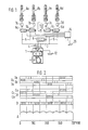
- FIG. 1 shows a schematic illustration of the fuel injection system according to the invention
- FIG. 2 shows a control diagram for Control of the distributor valves and the fuel quantity control valve via the crankshaft angle
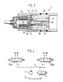
- FIG. 3 shows an exemplary embodiment of a distributor valve
- FIG. 4 shows a second exemplary embodiment of the invention with 3/3 solenoid valves in a schematic representation.
- a fuel injection system is described below with which fuel is injected directly into the combustion chambers of an internal combustion engine. This is possible both with self-igniting internal combustion engines and in a particularly advantageous manner with spark-ignited internal combustion engines, where, unlike with self-igniting internal combustion engines, the injection point in large crankshaft angle ranges of e.g. B. 0 to 360 degrees crankshaft angle can be selected. In such a system, e.g. B.
- a high-pressure pump 1 which can be designed as a known intermittently delivering in-line injection pump, radial piston injection pump or axial piston pump.
- a continuously delivering pump in particular a gear pump, can also be used to reduce pressure pulsations.
- the high-pressure injection pump has a plurality of pump pistons which are driven by corresponding drive cams and deliver fuel under high pressure in a fuel distributor.
- FIG. 1 shows three delivery lines 4 which, starting from the three pump work spaces of the three-cylinder high-pressure injection pumps, open into a distributor 3. From this branch injection lines 5, in each of which a 2/2 solenoid valve 6a to 6d serving as a distributor valve is arranged. Downstream of this valve there is a pressure valve 7a to 7d in the injection line, which is followed by the fuel injection valve 8a to 8d.
- a relief line 11 also branches off from the distributor 3 via an electrically controlled fuel injection quantity control valve 9, likewise designed as a 2/2 solenoid valve.
- the relief line 11 leads back to a fuel reservoir 12, from which the high-pressure injection pump is also supplied with fuel. Instead, the relief line can lead into a fuel supply space, which is kept at a low outlet pressure by a pre-feed pump.
- the high-pressure injection pump delivers the fuel with a constant delivery stroke to the distributor 3 in an uncontrolled manner.
- This is first relieved via the fuel injection quantity control valve 9, which is open when de-energized, and via the relief line 11, so that the fuel pressure required for injection is not reached.
- the distribution valves 6 are initially all closed and in the non-excited state.
- the solenoid valve assigned to the corresponding fuel injection valve 8, controlled by a control device 14 is opened so that the connection between the distributor 3 and the injection valve 8 is established. Only then is the fuel injection quantity control valve 9 closed.
- the high fuel pressure required before the injection then builds up, which is therefore only effective at the injection valve 8 controlled by the opened distributor valve 6.
- the fuel injection quantity control valve 9 is opened again and then the previously open distributor valve 6 is closed.
- the pressure control valve 7a to 7d is a valve of the type used in connection with injection lines in fuel injection pumps. It is a valve that opens in the delivery direction and closes at the end of the delivery, either relieving the pressure on the fuel injection line via a return suction collar or keeping it at a desired pressure level using a pressure relief valve.
- FIG. 2 An example of control times is shown in the diagram in FIG.
- the diagram part A of FIG. 2 shows the pulsating delivery of the high-pressure injection pump with three pump pistons and a corresponding translation of the drive between the fuel injection pump and the internal combustion engine.
- Diagram B shows the closing times of the normally open fuel injection quantity control valve 9.
- the opening times of the distributor valves are shown above this, the representation Ca representing the opening times of the control valve 6a and Cd showing the opening times of the distributor valve 6d.
- the injection times are shown as blocks, the sequences Da to Dd representing the injection times of the valves 8a to 8d.
- Suitable catalytic converters can also be connected downstream of such an internal combustion engine.
- the fuel is introduced into the combustion chamber during the suction stroke in the first or second quadrant of the crank stroke of the four-stroke internal combustion engine, so that the fuel can mix with the introduced air or distribute it homogeneously until the ignition point can.
- the fuel is most advantageously introduced into the combustion chamber at times of high air movement, which is estimated to drive in the region of the second quadrant of the crank path of the respective engine cylinder the crank arm lies.
- such an internal combustion engine can also be operated with a significantly leaner mixture.
- it is necessary to introduce the fuel shortly before ignition so that an ignitable mixture prevails near the spark plug.
- the air supply in such an operation is usually unthrottled, so that the combustion chamber is optimally filled.
- the start of injection must be placed late in the third and fourth quadrants of the crankshaft travel.
- a continuously delivering high pressure pump can be used or the drive of the high pressure injection pump can be selected so that the cam driving the pump piston gives the pump piston a constant delivery speed in the area of the expected injection.
- This is achieved with a so-called constant lift cam.
- constant stroke cams it is also possible to supply two injectors with fuel in succession from a single pump stroke of a pump piston of the high pressure injection pump, so that either the drive speed or the number of pump pistons of the high pressure injection pump can be reduced.
- the adaptation of the high-pressure injection pump to the internal combustion engine to be supplied must also take into account the number of cylinders in addition to the combustion process. The gear ratio must be selected accordingly.
- FIG. 1 it was shown that a 2/2-way solenoid valve is used in the injection line for each injection valve, which is closed in the non-excited state.
- a 3/3 solenoid valve 106a, 106b for every two injection valves, which in its de-energized idle position has closed the connection between fuel distributor 3 and fuel injection valves and in one excited position controls one of two injection valves and controls another fuel injector in its other excited position.
- the distributor valve 7 has a valve body 16 which has an annular groove 17 on the end face, between which and an axial bore 18 an annular valve seat 20 is formed. This has a central end ring opening 21 which is connected to the injection line 5 leading to the fuel injection valve. This leads parallel to the axis of the valve body from the ring opening 21 to the injection valve.
- the axial bore is connected to the distributor-side injection line 5, which opens radially into the valve body 16 and there into the axial bore 18.
- An annular, disk-shaped valve closing member 23, provided with a central opening 27, works together with the valve seat and is at the same time the armature of an electromagnet 24, which is placed tightly on the end face of the valve body 16.
- a return spring 26 is clamped between the core 25 of the electromagnet and the valve closing member, which holds the valve closing member in contact with the valve seat 20 and thereby closes the further fuel injection line 5 from the axial bore 18.
- the valve seat is designed here as a double seat valve and allows large flow cross sections to be opened quickly.
- the armature, as an annular disc has only a small mass and can thus quickly move from its open position into contact with the core 25 in the closed position.
- the closed position of the valve closing member is supported when pressure is applied from the side of the injection line through the surface of the valve closing member facing away from the valve seat, since the area between the valve closing member and the core 25 and the rest of the surrounding area, such as the annular groove 17 with the axial bore 18 in this position via the middle opening 27 of the valve closing member is connected.
- the fuel injection times can be varied within a very wide range in order to control, in particular, spark-ignited internal combustion engines that work with direct injection.
- the system is simple and inexpensive, and the various operating parameters such as the position of the accelerator pedal 29, the speed, the load conditions and environmental influences can be taken into account with a corresponding control device 14.
Landscapes
- Engineering & Computer Science (AREA)
- Chemical & Material Sciences (AREA)
- Combustion & Propulsion (AREA)
- Mechanical Engineering (AREA)
- General Engineering & Computer Science (AREA)
- Fuel-Injection Apparatus (AREA)
- High-Pressure Fuel Injection Pump Control (AREA)
- Electrical Control Of Air Or Fuel Supplied To Internal-Combustion Engine (AREA)
Applications Claiming Priority (2)
| Application Number | Priority Date | Filing Date | Title |
|---|---|---|---|
| DE4019586 | 1990-06-20 | ||
| DE4019586A DE4019586A1 (de) | 1990-06-20 | 1990-06-20 | Kraftstoffeinspritzsystem fuer brennkraftmaschinen |
Publications (2)
| Publication Number | Publication Date |
|---|---|
| EP0462404A1 true EP0462404A1 (fr) | 1991-12-27 |
| EP0462404B1 EP0462404B1 (fr) | 1994-04-13 |
Family
ID=6408695
Family Applications (1)
| Application Number | Title | Priority Date | Filing Date |
|---|---|---|---|
| EP91108163A Expired - Lifetime EP0462404B1 (fr) | 1990-06-20 | 1991-05-21 | Système d'injection de combustible pour moteurs à combustion interne |
Country Status (5)
| Country | Link |
|---|---|
| US (1) | US5213084A (fr) |
| EP (1) | EP0462404B1 (fr) |
| JP (1) | JPH04231677A (fr) |
| DE (2) | DE4019586A1 (fr) |
| ES (1) | ES2053234T3 (fr) |
Cited By (4)
| Publication number | Priority date | Publication date | Assignee | Title |
|---|---|---|---|---|
| WO1993022554A1 (fr) * | 1992-04-25 | 1993-11-11 | Robert Bosch Gmbh | Dispositif d'injection de carburant pour moteurs a combustion interne |
| GB2275307A (en) * | 1993-02-18 | 1994-08-24 | Bosch Gmbh Robert | I.c.engine high pressure distributor fuel injection system |
| EP0590362B1 (fr) * | 1992-09-29 | 1996-10-23 | Steyr Nutzfahrzeuge Ag | Agencement de came d'entraînement pour entrainer le piston d'une pompe d'injection pour un moteur à combustion interne |
| WO2002055872A1 (fr) * | 2001-01-12 | 2002-07-18 | Robert Bosch Gmbh | Systeme d'injection de carburant |
Families Citing this family (18)
| Publication number | Priority date | Publication date | Assignee | Title |
|---|---|---|---|---|
| US5297523A (en) * | 1993-02-26 | 1994-03-29 | Caterpillar Inc. | Tuned actuating fluid inlet manifold for a hydraulically-actuated fuel injection system |
| US5353766A (en) * | 1993-09-08 | 1994-10-11 | Cummins Engine Company, Inc. | Distributor for a high pressure fuel system |
| US5441027A (en) * | 1993-05-24 | 1995-08-15 | Cummins Engine Company, Inc. | Individual timing and injection fuel metering system |
| DE4318078A1 (de) * | 1993-06-01 | 1994-12-08 | Bosch Gmbh Robert | Kraftstoffeinspritzeinrichtung für Brennkraftmaschinen |
| GB2310889A (en) * | 1996-03-05 | 1997-09-10 | Lucas Ind Plc | Fuel supply system for solenoid-actuated fuel injectors |
| JP4445072B2 (ja) * | 1998-10-20 | 2010-04-07 | ヴェルトジィレ シュヴァイツ アクチェンゲゼルシャフト | ディーゼルエンジンのシリンダへの液体噴射装置及びディーゼルエンジン |
| JP4023020B2 (ja) * | 1999-02-19 | 2007-12-19 | トヨタ自動車株式会社 | 高圧燃料噴射系の燃料圧制御装置 |
| DE19918423A1 (de) * | 1999-04-23 | 2000-10-26 | Denys F Hackert | Einspritzanlage für flüssige Medien |
| DE19938169A1 (de) * | 1999-08-16 | 2001-03-01 | Bosch Gmbh Robert | Kraftstoffeinspritzeinrichtung |
| DE19939448A1 (de) * | 1999-08-20 | 2001-03-01 | Bosch Gmbh Robert | Injektor |
| DE10036868B4 (de) * | 2000-07-28 | 2004-07-29 | Robert Bosch Gmbh | Injektor für ein einen Hochdrucksammelraum umfassendes Einspritzsystem |
| US6568369B1 (en) | 2000-12-05 | 2003-05-27 | Caterpillar Inc | Common rail injector with separately controlled pilot and main injection |
| JP3884252B2 (ja) * | 2001-09-27 | 2007-02-21 | 三菱電機株式会社 | 高圧燃料供給装置用電磁弁 |
| AR055395A1 (es) * | 2005-08-26 | 2007-08-22 | Vertex Pharma | Compuestos inhibidores de la actividad de la serina proteasa ns3-ns4a del virus de la hepatitis c |
| CN102434349A (zh) * | 2011-09-30 | 2012-05-02 | 中国南方航空工业(集团)有限公司 | 燃油喷射系统以及具有该系统的航空发动机 |
| JP5672457B2 (ja) * | 2012-02-24 | 2015-02-18 | 三菱自動車工業株式会社 | 燃料貯留装置 |
| US9422898B2 (en) * | 2013-02-12 | 2016-08-23 | Ford Global Technologies, Llc | Direct injection fuel pump |
| US9638126B2 (en) * | 2013-04-12 | 2017-05-02 | Delbert Vosburg | Electronically controlled lean out device for mechanical fuel injected engines |
Citations (5)
| Publication number | Priority date | Publication date | Assignee | Title |
|---|---|---|---|---|
| FR1270580A (fr) * | 1960-07-18 | 1961-09-01 | Perfectionnements apportés à des dispositifs d'injection de combustible pour des moteurs à mouvement alternatif | |
| US3851635A (en) * | 1969-05-14 | 1974-12-03 | F Murtin | Electronically controlled fuel-supply system for compression-ignition engine |
| GB2060051A (en) * | 1979-10-05 | 1981-04-29 | Lucas Industries Ltd | Electrically-operated I.C. engine fuel injection systems |
| GB2165895A (en) * | 1984-10-06 | 1986-04-23 | Bosch Gmbh Robert | Fuel injection in internal combustion engines |
| EP0307947A2 (fr) * | 1987-09-16 | 1989-03-22 | Nippondenso Co., Ltd. | Pompe haute pression à débit variable |
Family Cites Families (9)
| Publication number | Priority date | Publication date | Assignee | Title |
|---|---|---|---|---|
| US4156560A (en) * | 1977-11-09 | 1979-05-29 | The United States Of America As Represented By The Secretary Of The Army | Electrically-controlled fuel injector |
| FR2449795B1 (fr) * | 1979-02-24 | 1986-11-28 | Huber Motorenbau Inst | Systeme d'injection pour moteur a combustion interne |
| DE3148671A1 (de) * | 1981-12-09 | 1983-07-21 | Robert Bosch Gmbh, 7000 Stuttgart | Kraftstoffeinspritzvorrichtung fuer brennkraftmaschinen, insbesondere fuer dieselmotoren |
| JPS58132139U (ja) * | 1982-03-02 | 1983-09-06 | 株式会社ボッシュオートモーティブ システム | 燃料噴射ポンプの燃料カツト装置 |
| US4674448A (en) * | 1985-07-04 | 1987-06-23 | Sulzer Brothers Limited | Fuel injection system for a multi-cylinder reciprocating internal combustion engine |
| US4757795A (en) * | 1986-04-21 | 1988-07-19 | Stanadyne, Inc. | Method and apparatus for regulating fuel injection timing and quantity |
| JP2521086B2 (ja) * | 1987-04-06 | 1996-07-31 | 株式会社ゼクセル | 燃料噴射ポンプの制御装置 |
| US5058553A (en) * | 1988-11-24 | 1991-10-22 | Nippondenso Co., Ltd. | Variable-discharge high pressure pump |
| US5109822A (en) * | 1989-01-11 | 1992-05-05 | Martin Tiby M | High pressure electronic common-rail fuel injection system for diesel engines |
-
1990
- 1990-06-20 DE DE4019586A patent/DE4019586A1/de not_active Withdrawn
-
1991
- 1991-05-13 US US07/699,016 patent/US5213084A/en not_active Expired - Fee Related
- 1991-05-21 EP EP91108163A patent/EP0462404B1/fr not_active Expired - Lifetime
- 1991-05-21 ES ES91108163T patent/ES2053234T3/es not_active Expired - Lifetime
- 1991-05-21 DE DE59101356T patent/DE59101356D1/de not_active Expired - Fee Related
- 1991-06-18 JP JP3145743A patent/JPH04231677A/ja active Pending
Patent Citations (5)
| Publication number | Priority date | Publication date | Assignee | Title |
|---|---|---|---|---|
| FR1270580A (fr) * | 1960-07-18 | 1961-09-01 | Perfectionnements apportés à des dispositifs d'injection de combustible pour des moteurs à mouvement alternatif | |
| US3851635A (en) * | 1969-05-14 | 1974-12-03 | F Murtin | Electronically controlled fuel-supply system for compression-ignition engine |
| GB2060051A (en) * | 1979-10-05 | 1981-04-29 | Lucas Industries Ltd | Electrically-operated I.C. engine fuel injection systems |
| GB2165895A (en) * | 1984-10-06 | 1986-04-23 | Bosch Gmbh Robert | Fuel injection in internal combustion engines |
| EP0307947A2 (fr) * | 1987-09-16 | 1989-03-22 | Nippondenso Co., Ltd. | Pompe haute pression à débit variable |
Non-Patent Citations (1)
| Title |
|---|
| PATENT ABSTRACTS OF JAPAN vol. 8, no. 64 (M-285)(1501) 27. März 1984 & JP-A-58 214 666 (SANWA ) 13. Dezember 1983 * |
Cited By (5)
| Publication number | Priority date | Publication date | Assignee | Title |
|---|---|---|---|---|
| WO1993022554A1 (fr) * | 1992-04-25 | 1993-11-11 | Robert Bosch Gmbh | Dispositif d'injection de carburant pour moteurs a combustion interne |
| EP0590362B1 (fr) * | 1992-09-29 | 1996-10-23 | Steyr Nutzfahrzeuge Ag | Agencement de came d'entraînement pour entrainer le piston d'une pompe d'injection pour un moteur à combustion interne |
| GB2275307A (en) * | 1993-02-18 | 1994-08-24 | Bosch Gmbh Robert | I.c.engine high pressure distributor fuel injection system |
| GB2275307B (en) * | 1993-02-18 | 1996-06-05 | Bosch Gmbh Robert | A fuel-injection system for internal combustion engines |
| WO2002055872A1 (fr) * | 2001-01-12 | 2002-07-18 | Robert Bosch Gmbh | Systeme d'injection de carburant |
Also Published As
| Publication number | Publication date |
|---|---|
| EP0462404B1 (fr) | 1994-04-13 |
| DE59101356D1 (de) | 1994-05-19 |
| DE4019586A1 (de) | 1992-01-02 |
| US5213084A (en) | 1993-05-25 |
| JPH04231677A (ja) | 1992-08-20 |
| ES2053234T3 (es) | 1994-07-16 |
Similar Documents
| Publication | Publication Date | Title |
|---|---|---|
| EP0462404B1 (fr) | Système d'injection de combustible pour moteurs à combustion interne | |
| DE3112381C2 (fr) | ||
| DE3788406T2 (de) | Elektronisch gesteuertes Einspritzsystem. | |
| DE3436768C2 (fr) | ||
| DE1808650A1 (de) | Kraftstoffeinspritzvorrichtung | |
| DE10023033A1 (de) | Verfahren zum Betreiben eines Kraftstoffzumesssystems einer direkteinspritzenden Brennkraftmaschine | |
| DE2126653A1 (de) | Kraftstoffeinspritzeinrichtung für Brennkraftmaschinen | |
| DE3148671C2 (fr) | ||
| DE2430733A1 (de) | Brennstoffeinspritzpumpe | |
| EP0114991B1 (fr) | Dispositif d'injection de carburant pour moteurs à combustion | |
| DE3634509A1 (de) | Verfahren zur lieferung von kraftstoff in einen verbrennungsmotor | |
| DE3823827A1 (de) | Kraftstoffeinspritzeinrichtung fuer brennkraftmaschinen, insbesondere pumpeduese | |
| DE2126787A1 (de) | Kraftstoffeinspntzeinrichtung fur Brennkraftmaschinen | |
| EP0287580A1 (fr) | Dispositif d'injection de carburant pour moteur a combustion interne, en particulier des moteurs diesel. | |
| EP0760425B1 (fr) | Dispositif d'injection | |
| DE19545162B4 (de) | Brennstoffeinspritzvorrichtung mit federvorgespanntem Steuerventil | |
| EP0178487B1 (fr) | Dispositif d'injection de carburant pour moteurs à combustion interne | |
| DE3382635T2 (de) | Verfahren und geraet fuer die genaue steuerung der kraftstoffeinspritzung in einer brennkraftmaschine. | |
| DE4341739C1 (de) | Einspritzsystem | |
| EP0327819B1 (fr) | Pompe à injection à carburant pour moteurs à combustion interne | |
| EP0298254A1 (fr) | Pompe à injection de combustible | |
| DE3437973A1 (de) | Kraftstoffeinspritzpumpe fuer brennkraftmaschinen | |
| DE19812170A1 (de) | Kraftstoffeinspritzanlage für eine mehrzylindrige Brennkraftmaschine | |
| DE2550722B2 (de) | Ventilgesteuerte hubkolben-brennkraftmaschine | |
| EP0540529B1 (fr) | Dispositif d'injection de carburant pour moteurs a combustion interne a allumage par etincelle |
Legal Events
| Date | Code | Title | Description |
|---|---|---|---|
| PUAI | Public reference made under article 153(3) epc to a published international application that has entered the european phase |
Free format text: ORIGINAL CODE: 0009012 |
|
| AK | Designated contracting states |
Kind code of ref document: A1 Designated state(s): DE ES FR GB IT |
|
| RAP3 | Party data changed (applicant data changed or rights of an application transferred) |
Owner name: ROBERT BOSCH GMBH |
|
| 17P | Request for examination filed |
Effective date: 19920603 |
|
| 17Q | First examination report despatched |
Effective date: 19930205 |
|
| GRAA | (expected) grant |
Free format text: ORIGINAL CODE: 0009210 |
|
| AK | Designated contracting states |
Kind code of ref document: B1 Designated state(s): DE ES FR GB IT |
|
| ET | Fr: translation filed | ||
| GBT | Gb: translation of ep patent filed (gb section 77(6)(a)/1977) |
Effective date: 19940419 |
|
| REF | Corresponds to: |
Ref document number: 59101356 Country of ref document: DE Date of ref document: 19940519 |
|
| ITF | It: translation for a ep patent filed | ||
| REG | Reference to a national code |
Ref country code: ES Ref legal event code: FG2A Ref document number: 2053234 Country of ref document: ES Kind code of ref document: T3 |
|
| PLBE | No opposition filed within time limit |
Free format text: ORIGINAL CODE: 0009261 |
|
| STAA | Information on the status of an ep patent application or granted ep patent |
Free format text: STATUS: NO OPPOSITION FILED WITHIN TIME LIMIT |
|
| 26N | No opposition filed | ||
| PGFP | Annual fee paid to national office [announced via postgrant information from national office to epo] |
Ref country code: GB Payment date: 19970506 Year of fee payment: 7 |
|
| PGFP | Annual fee paid to national office [announced via postgrant information from national office to epo] |
Ref country code: FR Payment date: 19970523 Year of fee payment: 7 |
|
| PGFP | Annual fee paid to national office [announced via postgrant information from national office to epo] |
Ref country code: ES Payment date: 19970531 Year of fee payment: 7 |
|
| PGFP | Annual fee paid to national office [announced via postgrant information from national office to epo] |
Ref country code: DE Payment date: 19970724 Year of fee payment: 7 |
|
| PG25 | Lapsed in a contracting state [announced via postgrant information from national office to epo] |
Ref country code: GB Free format text: LAPSE BECAUSE OF NON-PAYMENT OF DUE FEES Effective date: 19980521 |
|
| PG25 | Lapsed in a contracting state [announced via postgrant information from national office to epo] |
Ref country code: ES Free format text: LAPSE BECAUSE OF NON-PAYMENT OF DUE FEES Effective date: 19980522 |
|
| PG25 | Lapsed in a contracting state [announced via postgrant information from national office to epo] |
Ref country code: FR Free format text: LAPSE BECAUSE OF NON-PAYMENT OF DUE FEES Effective date: 19980531 |
|
| GBPC | Gb: european patent ceased through non-payment of renewal fee |
Effective date: 19980521 |
|
| PG25 | Lapsed in a contracting state [announced via postgrant information from national office to epo] |
Ref country code: DE Free format text: LAPSE BECAUSE OF NON-PAYMENT OF DUE FEES Effective date: 19990302 |
|
| REG | Reference to a national code |
Ref country code: FR Ref legal event code: ST |
|
| REG | Reference to a national code |
Ref country code: ES Ref legal event code: FD2A Effective date: 20000403 |
|
| PG25 | Lapsed in a contracting state [announced via postgrant information from national office to epo] |
Ref country code: IT Free format text: LAPSE BECAUSE OF NON-PAYMENT OF DUE FEES;WARNING: LAPSES OF ITALIAN PATENTS WITH EFFECTIVE DATE BEFORE 2007 MAY HAVE OCCURRED AT ANY TIME BEFORE 2007. THE CORRECT EFFECTIVE DATE MAY BE DIFFERENT FROM THE ONE RECORDED. Effective date: 20050521 |