EP0462462A1 - Procédé et dispositif de teinture des textiles - Google Patents
Procédé et dispositif de teinture des textiles Download PDFInfo
- Publication number
- EP0462462A1 EP0462462A1 EP91109372A EP91109372A EP0462462A1 EP 0462462 A1 EP0462462 A1 EP 0462462A1 EP 91109372 A EP91109372 A EP 91109372A EP 91109372 A EP91109372 A EP 91109372A EP 0462462 A1 EP0462462 A1 EP 0462462A1
- Authority
- EP
- European Patent Office
- Prior art keywords
- brushes
- steam
- conveyor belt
- textile
- liquor
- Prior art date
- Legal status (The legal status is an assumption and is not a legal conclusion. Google has not performed a legal analysis and makes no representation as to the accuracy of the status listed.)
- Granted
Links
- 239000004753 textile Substances 0.000 title claims abstract description 80
- 238000000034 method Methods 0.000 title claims abstract description 32
- 238000004043 dyeing Methods 0.000 title claims abstract description 8
- 239000000463 material Substances 0.000 claims abstract description 12
- 239000004744 fabric Substances 0.000 claims abstract description 9
- 239000003973 paint Substances 0.000 claims description 42
- 238000004026 adhesive bonding Methods 0.000 claims description 6
- 239000002245 particle Substances 0.000 claims description 5
- 238000004040 coloring Methods 0.000 claims description 4
- 229920002457 flexible plastic Polymers 0.000 claims description 3
- 238000010438 heat treatment Methods 0.000 claims description 3
- 239000007769 metal material Substances 0.000 claims description 3
- 238000003801 milling Methods 0.000 claims description 3
- 239000011248 coating agent Substances 0.000 claims description 2
- 238000000576 coating method Methods 0.000 claims description 2
- 239000003086 colorant Substances 0.000 claims description 2
- 239000000835 fiber Substances 0.000 claims description 2
- 229920003023 plastic Polymers 0.000 claims description 2
- 239000004033 plastic Substances 0.000 claims description 2
- 238000011084 recovery Methods 0.000 claims description 2
- 229910001220 stainless steel Inorganic materials 0.000 claims description 2
- 239000010935 stainless steel Substances 0.000 claims description 2
- 239000003292 glue Substances 0.000 claims 1
- 238000010422 painting Methods 0.000 claims 1
- 238000003825 pressing Methods 0.000 claims 1
- 239000003082 abrasive agent Substances 0.000 description 4
- 239000000126 substance Substances 0.000 description 3
- 238000005406 washing Methods 0.000 description 3
- 230000000694 effects Effects 0.000 description 2
- 239000013013 elastic material Substances 0.000 description 2
- 206010020751 Hypersensitivity Diseases 0.000 description 1
- 238000005299 abrasion Methods 0.000 description 1
- 208000026935 allergic disease Diseases 0.000 description 1
- 230000007815 allergy Effects 0.000 description 1
- 230000015572 biosynthetic process Effects 0.000 description 1
- 239000007844 bleaching agent Substances 0.000 description 1
- 230000002860 competitive effect Effects 0.000 description 1
- 239000003599 detergent Substances 0.000 description 1
- 208000037265 diseases, disorders, signs and symptoms Diseases 0.000 description 1
- 238000004090 dissolution Methods 0.000 description 1
- 238000005516 engineering process Methods 0.000 description 1
- 230000007613 environmental effect Effects 0.000 description 1
- 238000003912 environmental pollution Methods 0.000 description 1
- 239000012530 fluid Substances 0.000 description 1
- 239000006260 foam Substances 0.000 description 1
- 238000005470 impregnation Methods 0.000 description 1
- 238000003754 machining Methods 0.000 description 1
- 238000004519 manufacturing process Methods 0.000 description 1
- 239000008262 pumice Substances 0.000 description 1
- 230000000284 resting effect Effects 0.000 description 1
- 239000004576 sand Substances 0.000 description 1
- 239000007858 starting material Substances 0.000 description 1
- 238000011144 upstream manufacturing Methods 0.000 description 1
Images



Classifications
-
- D—TEXTILES; PAPER
- D06—TREATMENT OF TEXTILES OR THE LIKE; LAUNDERING; FLEXIBLE MATERIALS NOT OTHERWISE PROVIDED FOR
- D06B—TREATING TEXTILE MATERIALS USING LIQUIDS, GASES OR VAPOURS
- D06B1/00—Applying liquids, gases or vapours onto textile materials to effect treatment, e.g. washing, dyeing, bleaching, sizing or impregnating
- D06B1/10—Applying liquids, gases or vapours onto textile materials to effect treatment, e.g. washing, dyeing, bleaching, sizing or impregnating by contact with a member carrying the treating material
- D06B1/12—Applying liquids, gases or vapours onto textile materials to effect treatment, e.g. washing, dyeing, bleaching, sizing or impregnating by contact with a member carrying the treating material by rubbing contact, e.g. with brushes or pads
-
- D—TEXTILES; PAPER
- D06—TREATMENT OF TEXTILES OR THE LIKE; LAUNDERING; FLEXIBLE MATERIALS NOT OTHERWISE PROVIDED FOR
- D06B—TREATING TEXTILE MATERIALS USING LIQUIDS, GASES OR VAPOURS
- D06B1/00—Applying liquids, gases or vapours onto textile materials to effect treatment, e.g. washing, dyeing, bleaching, sizing or impregnating
- D06B1/04—Applying liquids, gases or vapours onto textile materials to effect treatment, e.g. washing, dyeing, bleaching, sizing or impregnating by pouring or allowing to flow on to the surface of the textile material
-
- D—TEXTILES; PAPER
- D06—TREATMENT OF TEXTILES OR THE LIKE; LAUNDERING; FLEXIBLE MATERIALS NOT OTHERWISE PROVIDED FOR
- D06P—DYEING OR PRINTING TEXTILES; DYEING LEATHER, FURS OR SOLID MACROMOLECULAR SUBSTANCES IN ANY FORM
- D06P7/00—Dyeing or printing processes combined with mechanical treatment
Definitions
- the invention relates to a method for dyeing textiles, in which the surfaces of the textiles are mechanically processed at the same time as the dyeing in such a way that signs of wear occur and that the fabric softens.
- a method for this in which either the finished piece or the starting material (by the meter) is initially used is completely provided with the color, whereupon the color is washed out up to 95% in a washing and wear process and at the same time the wear effect is achieved during this washing process by adding abrasives such as sand and / or pumice or the like.
- a disadvantage of this known method is that it is relatively time-consuming, on the one hand, because most of the previously applied paint has to be removed again, which also means that a relatively high amount of energy is used, and on the other hand, the environment is removed by the color removed from the fabric pieces is heavily burdened. In addition, the cost of materials for color and detergents is considerable.
- the invention is accordingly based on the object of providing a method of the type mentioned at the outset with which it is possible to keep both the energy and material expenditure and the environmental impact as low as possible.
- the textile pieces can also be soaked with the dye liquor so that the coloring is reflected on the back of the textile, i.e. on the side of the textiles facing away from the brushes, which can be favored in particular by the steam liquor being acted upon by steam, which is drawn in and pulling through the textile pieces favored.
- the steam is normal wet steam with a temperature of about 100 ° to 120 ° C.
- Any excess portions of the dye liquor that pass the textile pieces can expediently be collected and returned to the dye liquor.
- the device expediently consists of a series of horizontally arranged receptacles for the paint liquor with separate outlet channels which are directed at the bristles of the brushes which are arranged rotatably below the containers.
- At least one conveyor belt runs continuously below the brushes, on which the textile pieces are placed.
- the conveyor belt bears against the bristles of the brushes under pretension.
- the textiles are not only colored by the brushes, but are also processed in their surface in the manner described above due to the pretension.
- the conveyor belt expediently consists of an elastic material provided with openings so that the excess liquor of paint can pass through the conveyor belt into a receiving trough which is expediently arranged below the conveyor belt.
- a rubber in particular a textile fiber reinforced rubber.
- the device is designed such that the front and the back of the textile pieces can be processed in the same way in one operation.
- a deflection device and a second conveyor belt arranged below the first are expediently provided, which are also acted upon by brushes which run above the second conveyor belt.
- the textile pieces are thus conveyed into the deflection device by the first conveyor belt, then gripped by the second conveyor belt and pulled through the device for the second time.
- the deflection device can consist of a guide plate which guides the textile pieces to the second conveyor belt.
- the individual receptacles have at least one steam line at their exits are connected, the supply channel for the supply of the paint liquor to the brushes can also supply the steam at the same time, so that the impregnation is brought about. It is also advantageous if at least one compressed air line is arranged in the receptacles, which has outlet openings facing the interior of the individual receptacles, in order to swirl the paint liquor and keep it moving, so that paint components cannot settle.
- the feed channels for the paint liquor can be shut off individually, appropriate shut-off valves being expediently arranged in the immediate vicinity of the surfaces of the brushes.
- These feed channels can also be provided with a bypass which feeds the paint liquor past the valves past the second row of processing brushes assigned to the second conveyor belt, so that the closed valves can be bypassed.
- steam can be expediently fed to the brushes by means of a steam nozzle in the region of the guide plate before processing the back of the textile pieces, so that steam also dampens the back of the textile pieces to be treated.
- the arrangement according to the invention can be used in many different ways.
- the intensity of the color in the individual receptacles can be different; Different colors can be provided in the individual containers, and the valves can be adjusted in sections so that either no or a different amount of liquor reaches the brushes.
- the receptacles can be heated, and the temperatures in the individual receptacles can be different, so that this results in different drawing speeds for the dye liquor.
- the distance between the axes or shafts of the brushes and the conveyor belts can also be adjustable, so that in this way the pretension with which the weary processing of the textiles is carried out changes.
- All brushes can be provided with a common drive, for example a chain drive, so that a single drive motor is sufficient to drive the brushes.
- intermediate brushes can be arranged, which have a smaller diameter and are not necessarily used for the application of paint, but only for the wearing treatment of the surfaces of the textiles.
- the conveyor belts can be subdivided, or the brushes can run at different speeds, so that folds result in the pieces of tissue that are subject to particular wear and tear from the brushes. For the same reasons, it is possible to provide further intermediate brushes which rotate in the opposite direction to the main brushes which determine the direction of conveyance.
- Another brush set in each row of brushes can be used as a hold-down.
- the additional device expediently has a plurality of steam nozzles and at least one supply line for the supply of Heating steam and / or wet steam to the steam nozzles.
- the paint nozzles can also be acted upon by a compressed air line and / or by the steam lines.
- a container containing the paint can expediently be assigned to the compressed air line, which container there has the shape of a Venturi tube for removing paint particles.
- the hold-down brushes which are arranged between the processing brushes and have a much smaller diameter than these, are not designed as bristle brushes, as in the previous exemplary embodiments, but as sponge brushes, which consist of a cylindrical tubular fitting mounted on a shaft, which is firmly connected to the shaft by gluing or the like.
- sponge brushes has the advantage that due to the stronger adhesion to the piece of textile Crumple zones result, which form a pattern or line formation on the textile piece and have a higher coloring than the surroundings.
- such sponge brushes are generally not used as wearing tools, but rather as crumple and application brushes for the colored material.
- squeezing can also be brought about by the fact that in the area of the folds due to the pushing together of the textile piece in this area there is a stronger color print and thus a reproduction of the pattern thus produced.
- the hold-down brushes made of sponges can be adjusted forwards, backwards, upwards or downwards in their position relative to the neighboring bristle brushes, a different setting of the height of the waves carrying the sponges to the surface of the conveyor belt also being considered is coming. If the shaft is brought closer to the conveyor belt, this means that the cylindrical sponge coating is compressed more in this area, which at the same time means a higher pressure on the textile piece in this area and thus leads to patterns which deviate therefrom.
- the contour applied by means of the sponges is inherently much clearer than that which arises according to the first embodiment by bristle brushes, for example by the hold-down brushes, so that in the sponge version the contour applied in any case despite the dissolution by the downstream bristle brushes largely preserved.
- the sponge roller brushes can run in opposite directions to the adjacent bristle brush rollers, which leads to a further increase in the resolution of the contour due to the relative movement caused thereby.
- the textile pieces can also be guided along on a smooth and flat sliding surface by means of the brushes, their feed being effected by the main brushes acting in the feed direction.
- This main feed is not affected by the fact that occasionally opposed Working brushes, such as the hold-down brushes or the sponge roller brushes, are provided, since the feed forces applied by the main brushes are in any case a multiple of the forces of the counter-rotating sponge brush rollers.
- This sliding surface can consist of a polished stainless steel, a smooth, wear-resistant plastic or the like, so that the movement of the textile pieces along this surface is not hindered.
- the sliding surface can be provided with openings pointing downwards, through which the excess paint or the excess paint material (the paint liquor) can drip off and be collected there.
- the liquor discharged in this way can be reintroduced into the liquor tank in the upper region of the device.
- certain forms of patterns can also be deliberately achieved by physically applying pattern pieces to the surface of the sponge brush roller, which can be done by gluing or, for example, by applying a sponge brush roller over the entire surface a network is maintained, which holds the above items on this.
- a network has the advantage that the contour that is to be created by the sample appears to be dissolved (smoothed).
- the sample can consist of a textile, a flexible plastic, but also of a flexible metal material.
- Another possibility for generating the pattern is that recesses are made in the surface of the sponge roller brushes, for example by milling, which form the pattern contours.
- the net drawn over the sample pieces and the sponge rollers can also be a textile material, for example a coarse-meshed textile material, the stitches of which can then be found as a pattern on the textile piece to be dyed.
- a plurality of rotating and driven brushes 1 are provided, which apply the dye liquor to the textiles to be processed.
- the paint liquor is located in a row of receptacles 2, each of which has separate outlets 3 in the form of shaft-like channels or lines, which are directed towards the bristles of the brushes 1 arranged below the container 2.
- outlets 3 in the form of shaft-like channels or lines, which are directed towards the bristles of the brushes 1 arranged below the container 2.
- FIG. 1 the perspective representation of the containers 2, the outlets 3 and the brushes 1 is only indicated schematically in FIG. 1.
- the outlet lines 3 for the paint liquor can be shut off individually by shut-off valves 4, the shut-off valves 4 being arranged in the immediate vicinity of the surfaces of the brushes 1.
- the outlet lines 3 can also be provided with a bypass 5, which feeds the paint liquor past the valves 4 past a second row of outlet lines 6 with valves 7 and via these to a second row of brushes 8.
- This type of direction of movement is also represented in FIG. 2 by the arrow 11.
- the pieces of textile to be processed are thus entered into the device above the conveyor belt 9 on the right in FIGS. 1 and 2 and processed in the manner described by the rotating brushes 1 resting on this conveyor belt under tension.
- the dye liquor is fed to the textile pieces via the feed chutes 3 and the brushes 1 and, in addition, due to the prestressing, they are also machined in their surface.
- the conveyor belt 9 is provided in the area of its upper run in a manner known per se with small support rollers 12, so that the pre-tension is maintained over the entire length of the conveyor belt.
- the conveyor belt 9 consists of an elastic material provided with openings so that the excess liquor of paint can get down into a receiving trough 13 arranged below the conveyor belt 9.
- a deflection device in the form of a guide plate 14 which the textile pieces conveyed out of the first brush set 1 in the direction of arrow 15 and processed on one side, the second lower brush set with the brushes 8 feeds.
- the textile pieces are deflected in the direction of arrow 16 by the guide plate 14. They then pass through the second lower brush set in the direction of arrows 17 and are conveyed out at 18.
- the structure of the lower conveyor belt 19, which is guided over rollers 20 and the upper run of which is also held against the brushes 8 by support rollers 12, corresponds to that of the upper conveyor belt 9.
- the individual receptacles 2 are in the area of their container-side outputs with a steam line 21, so that via the outlet line 3 for the paint liquor steam can also be supplied to brushes 1 and 8.
- a compressed air line 22 can be arranged in each of the containers 2, which has outlet openings facing the interior of the individual containers, so that air is blown into the containers in order to swirl the paint liquor and keep it moving.
- At least one steam nozzle 23 can be provided in the region of the guide plate 14, so that the back of the textile pieces to be treated is also moistened by the steam during the deflection.
- the distance between the brush axes and the conveyor belts 9 and 19 can be adjustable, so that the pretension between the conveyor belt surface and the bristles can be changed.
- the main brushes 1 which are essentially used for processing are arranged next to one another on common shafts 26 and also one behind the other.
- Smaller intermediate brushes 24 can be arranged in the spaces that result, which may not be used for the application of paint, but only for the wearing treatment of the surfaces of the textiles.
- they can act as hold-downs for the textiles in order to prevent the textiles to be treated from being pulled up or displaced.
- additional intermediate brushes 25 can be provided which rotate in the opposite direction to the main brushes 1 which determine the conveying direction and thus produce folds which are subject to particular wear and tear from the brushes.
- Fig. 3 shows a schematic representation of the brush sets 1 and 8, and their common drive 29 and 30, which can be a chain drive, for example.
- the intermediate brushes 25 shown here and rotating in the opposite direction are actuated by appropriate guidance of the common drive.
- the forces which can be transmitted to the textiles by the intermediate brushes 25 moving in the opposite direction can amount to approximately 25% of the total forces acting on the textiles.
- the speed of the drive can be infinitely variable so that the brushes 1 of the upper brush set can rotate at a different speed than the brushes 8 of the lower brush set.
- FIG. 4 shows a schematic representation of the small intermediate brushes 24 which act as hold-down devices (cf. also FIG. 2) for the upper and lower brush set of the device.
- These intermediate brushes 24 can also be provided with drives 31 and 32 designed as a chain drive, the chain drives here also being controllable.
- the intermediate brushes 24 and 25 (see FIG. 2), including their drives, can be detachably inserted as a structural unit between the main brushes 1.
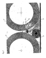
- an additional device 40 is arranged between two rotating main brushes 8, with which a dyeing process as such can be further refined compared to that according to the above-mentioned embodiments and thus improved.
- the body of the additional device 40 has schematically indicated steam nozzles 41 which, as shown, can be directed against at least one of the rotating brushes 8 and which can be acted upon by a steam line 42, for example by a steam heating line.
- the line 42 is also connected to the base body of the additional device 40.
- the steam nozzles 41 can alternatively or simultaneously be subjected to wet steam via a further line 43.
- the steam nozzles are adjustable according to the requirements.
- paint nozzles 44 are provided, which can be connected to a compressed air line, not shown, and / or can be acted upon by the steam lines 42 and 43.
- the paint supply is located in a container, not shown, to which the compressed air line can be guided in the form of a Venturi tube, so that the paint can be supplied to the paint nozzles 44 in an atomized form.
- the paint particles emerge finely distributed from the paint nozzles 44, so that they can be gripped by the brushes 8 and 24 and introduced into the fabric 45 in the manner described.
- the known methods also have a dye consumption which is up to 50 times higher, as well as a high consumption of chemicals, bleaching agents and abrasives, the latter not being able to be rinsed out of the fabric without residues despite intensive rinsing of 70 l and more per part.
- the arrangement according to the invention almost completely dispenses with the use of the chemicals and abrasives mentioned above, so that rinsing out is no longer necessary.
- the method carried out with the arrangement according to the invention is otherwise disposal-free and correspondingly skin-friendly.
- the fabric is dyed step by step and in layers only up to the desired color level and since a basic dyeing has to be washed out again, this environmentally harmful operation is completely eliminated.
- the brush technique on which the invention is based achieves a significantly higher degree of softness, so that the fabric becomes comparatively more fluid.
- the arrangement according to the invention makes it possible to produce differently colored textiles or clothing items in a single operation.
- Fig. 6 shows a perspective view of a modified embodiment in which the hold-down rollers 24 (see FIG. 2) are not designed as bristle brush rollers, but as sponge rollers. These consist of a tubular shaped piece 51, which is attached to the associated shaft 50 by gluing or the like. The tubular shaped part 51 made of sponge can sit on the shaft 50 under prestress.
- the sponge roller 52 thus formed serves primarily not to wear out the textile pieces to be treated, but rather to apply paint in the manner described above, the textile pieces being squeezed and crumpled by the sponge rollers 52, so that a stronger ink application occurs in the fold area thus produced .
- the shaft 50 can be moved more or less close to the conveyor belt 9 or to the upstream and downstream brush rollers 1 upwards, downwards and to the side in order to influence the identity of the paint application and possibly the subsequent resolution of the contour in the desired manner .
- Appropriate adjustment devices for the shaft 50 are provided for this purpose.
- the tubular foam covering 51 can also be covered by a net 53 and fastened to the shaft 50, the net, as shown, being of large mesh so that the individual meshes 54 are on the surface map the sponge roller 52.
- the net 53 can be guided around the sponge roller 52 in the direction of the arrows 55, the free ends 56 of the net 53 overlapping.
- certain preformed patterns 57 can be physically applied, which can be done by gluing or by the fact that the net 53 simultaneously holds these patterns. In the latter case, in addition to the pattern 57, the image of the meshes 54 would be found on the sponge roller 52.
- the pattern 57 can consist of a textile, a flexible plastic or also of a flexible metal material.
Landscapes
- Engineering & Computer Science (AREA)
- Textile Engineering (AREA)
- Treatment Of Fiber Materials (AREA)
- Coloring (AREA)
Applications Claiming Priority (2)
| Application Number | Priority Date | Filing Date | Title |
|---|---|---|---|
| DE4018835A DE4018835A1 (de) | 1990-06-13 | 1990-06-13 | Verfahren und vorrichtung zur einfaerbung von textilien |
| DE4018835 | 1990-06-13 |
Publications (2)
| Publication Number | Publication Date |
|---|---|
| EP0462462A1 true EP0462462A1 (fr) | 1991-12-27 |
| EP0462462B1 EP0462462B1 (fr) | 1994-08-10 |
Family
ID=6408285
Family Applications (1)
| Application Number | Title | Priority Date | Filing Date |
|---|---|---|---|
| EP91109372A Expired - Lifetime EP0462462B1 (fr) | 1990-06-13 | 1991-06-07 | Procédé et dispositif de teinture des textiles |
Country Status (6)
| Country | Link |
|---|---|
| US (1) | US5195202A (fr) |
| EP (1) | EP0462462B1 (fr) |
| AT (1) | ATE109841T1 (fr) |
| DE (2) | DE4018835A1 (fr) |
| DK (1) | DK0462462T3 (fr) |
| ES (1) | ES2062616T3 (fr) |
Cited By (1)
| Publication number | Priority date | Publication date | Assignee | Title |
|---|---|---|---|---|
| US6790661B1 (en) * | 1999-07-16 | 2004-09-14 | Verax Biomedical, Inc. | System for detecting bacteria in blood, blood products, and fluids of tissues |
Families Citing this family (1)
| Publication number | Priority date | Publication date | Assignee | Title |
|---|---|---|---|---|
| CN108950937A (zh) * | 2018-07-20 | 2018-12-07 | 绍兴绍恩机械有限公司 | 一种高效清洗及过滤布毛机构 |
Citations (2)
| Publication number | Priority date | Publication date | Assignee | Title |
|---|---|---|---|---|
| DE2425168A1 (de) * | 1973-05-30 | 1975-01-02 | Quikoton Ag | Verfahren zur herstellung eines gefaerbten textilen flaechengebildes und danach hergestellte textilien |
| DE3524557A1 (de) * | 1985-07-10 | 1987-01-15 | Mageba Textilmaschinen Gmbh | Vorrichtung zur behandlung von laufenden baendern |
Family Cites Families (9)
| Publication number | Priority date | Publication date | Assignee | Title |
|---|---|---|---|---|
| AT29129B (de) * | 1906-08-27 | 1907-07-10 | Carl Kuebler | Verfahren zur gleichmäßigen Auftragen geringfügiger Flüssigkeitsmengen auf Stoffe. |
| US2199093A (en) * | 1937-12-22 | 1940-04-30 | Harry C Wolfenden | Dye spattering machine |
| US2648088A (en) * | 1949-07-26 | 1953-08-11 | Dewey And Almy Chem Comp | Textile print blanket washing equipment |
| US2820358A (en) * | 1954-08-20 | 1958-01-21 | Ind Rayon Corp | Apparatus for applying a treating solution to reels and the like |
| CA959721A (en) * | 1969-12-17 | 1974-12-24 | Cecil M. Burns | Precision deposition onto a textile substrate |
| GB1458046A (en) * | 1973-10-02 | 1976-12-08 | Special Equipment Ltd | Carpet treating machines |
| DE3377147D1 (en) * | 1982-08-16 | 1988-07-28 | Toray Industries | Apparatus for raising or cropping surface of textile fabrics |
| US4648250A (en) * | 1984-06-15 | 1987-03-10 | Suminoe Textile Co., Ltd. | Apparatus for dyeing a web of fabric continuously |
| US4951366A (en) * | 1989-02-07 | 1990-08-28 | Geller George R | Method for modifying fabrics to produce varied effects |
-
1990
- 1990-06-13 DE DE4018835A patent/DE4018835A1/de not_active Withdrawn
-
1991
- 1991-06-07 EP EP91109372A patent/EP0462462B1/fr not_active Expired - Lifetime
- 1991-06-07 DE DE59102475T patent/DE59102475D1/de not_active Expired - Fee Related
- 1991-06-07 DK DK91109372.2T patent/DK0462462T3/da active
- 1991-06-07 ES ES91109372T patent/ES2062616T3/es not_active Expired - Lifetime
- 1991-06-07 AT AT91109372T patent/ATE109841T1/de not_active IP Right Cessation
- 1991-06-13 US US07/713,378 patent/US5195202A/en not_active Expired - Fee Related
Patent Citations (2)
| Publication number | Priority date | Publication date | Assignee | Title |
|---|---|---|---|---|
| DE2425168A1 (de) * | 1973-05-30 | 1975-01-02 | Quikoton Ag | Verfahren zur herstellung eines gefaerbten textilen flaechengebildes und danach hergestellte textilien |
| DE3524557A1 (de) * | 1985-07-10 | 1987-01-15 | Mageba Textilmaschinen Gmbh | Vorrichtung zur behandlung von laufenden baendern |
Cited By (1)
| Publication number | Priority date | Publication date | Assignee | Title |
|---|---|---|---|---|
| US6790661B1 (en) * | 1999-07-16 | 2004-09-14 | Verax Biomedical, Inc. | System for detecting bacteria in blood, blood products, and fluids of tissues |
Also Published As
| Publication number | Publication date |
|---|---|
| EP0462462B1 (fr) | 1994-08-10 |
| ATE109841T1 (de) | 1994-08-15 |
| US5195202A (en) | 1993-03-23 |
| DE59102475D1 (de) | 1994-09-15 |
| DE4018835A1 (de) | 1991-12-19 |
| ES2062616T3 (es) | 1994-12-16 |
| DK0462462T3 (da) | 1994-09-26 |
Similar Documents
| Publication | Publication Date | Title |
|---|---|---|
| DE69306464T2 (de) | Verfahren und Vorrichtung zum Behandeln eines bandförmigen Materials | |
| DE202004000662U1 (de) | Maschine zum Bedrucken der Schmalseiten plattenförmiger Werkstücke | |
| DE1710743B1 (de) | Verfahren und Vorrichtung zur Behandlung von Pol- oder Florgeweben | |
| DE2143065A1 (de) | Verfahren und Vorrichtung zur Bearbeitung von Florgeweben | |
| DE2438887A1 (de) | Verfahren und vorrichtung zum behandeln schlauchfoermiger textilware im nasszustand | |
| EP0462462B1 (fr) | Procédé et dispositif de teinture des textiles | |
| DE3141508A1 (de) | Verfahren und vorrichtung zum reinigen, oeffnen und orientieren des flors von samtstoffen und aehnlichen materialien | |
| DE60201460T2 (de) | Vorrichtung und Verfahren zur Nassbehandlung einer strangförmigen Warenbahn | |
| DE1460452C3 (de) | Verfahren zur Veredlung einer synthetischen Textilstoffbahn | |
| DE9318650U1 (de) | Auftragevorrichtung für die Beschichtung mit Lack o.dgl. | |
| EP0075073B1 (fr) | Procédé et appareil de traitement au mouillé de matières textiles | |
| DE69501471T2 (de) | Vorrichtung zum künstlichen altern und nachbehandeln von einem stoff | |
| DE2446233A1 (de) | Verfahren und vorrichtung zur bildung einer fadenlage, wie eines vlieses oder dgl., auf einer transporteinrichtung | |
| DE2430135A1 (de) | Vorrichtung zum beeinflussen, insbesondere waschen, von tuchware | |
| DE102006030551A1 (de) | Vorrichtung zum Aufbringen von härtbarem, reibungserzeugendem Material auf einer Bandware | |
| DE19905317A1 (de) | Vorrichtung zum Auftragen eines flüssigen oder pastösen Auftragsmediums auf einen laufenden Untergrund | |
| DE2756065C3 (de) | Verfahren und Vorrichtung zum mustergemäßen Scheren der Fasern von Florware | |
| DE2549143A1 (de) | Verfahren und vorrichtung zum bearbeiten von textilmaterialien | |
| EP1841911A1 (fr) | Procede et dispositif pour realiser des motifs dans des matieres colorees par un traitement par jets d'eau | |
| DE2221679A1 (de) | Verfahren und Vorrichtung zum Behandeln von Textilstoffen in einem Behandlungsbad | |
| DE2928565A1 (de) | Vorrichtung zum praegen einer auf ein textilgut aufgebrachten beschichtungsmasse | |
| DE3023000A1 (de) | Verfahren und vorrichtung zum rueckdrehen, entzwirnen bzw. kreppen einer stoffbahn | |
| DE10130094B4 (de) | Abquetsch- und Formmaschine für Maschenware | |
| DE3013738A1 (de) | Vorrichtung zum entwaessern eines poroesen stoffes, insbesondere eines teppichs | |
| EP0093353A2 (fr) | Dispositif pour l'étendage ou le lissage de matériaux plats, mous et flexibles, notamment des peaux entières en cuir naturel |
Legal Events
| Date | Code | Title | Description |
|---|---|---|---|
| PUAI | Public reference made under article 153(3) epc to a published international application that has entered the european phase |
Free format text: ORIGINAL CODE: 0009012 |
|
| AK | Designated contracting states |
Kind code of ref document: A1 Designated state(s): AT BE CH DE DK ES FR GB GR IT LI LU NL SE |
|
| 17P | Request for examination filed |
Effective date: 19920616 |
|
| 17Q | First examination report despatched |
Effective date: 19930917 |
|
| ITF | It: translation for a ep patent filed | ||
| RAP1 | Party data changed (applicant data changed or rights of an application transferred) |
Owner name: HAMANN, HANS-JOERG |
|
| RIN1 | Information on inventor provided before grant (corrected) | ||
| GRAA | (expected) grant |
Free format text: ORIGINAL CODE: 0009210 |
|
| AK | Designated contracting states |
Kind code of ref document: B1 Designated state(s): AT BE CH DE DK ES FR GB GR IT LI LU NL SE |
|
| REF | Corresponds to: |
Ref document number: 109841 Country of ref document: AT Date of ref document: 19940815 Kind code of ref document: T |
|
| GBT | Gb: translation of ep patent filed (gb section 77(6)(a)/1977) |
Effective date: 19940810 |
|
| REF | Corresponds to: |
Ref document number: 59102475 Country of ref document: DE Date of ref document: 19940915 |
|
| REG | Reference to a national code |
Ref country code: DK Ref legal event code: T3 |
|
| REG | Reference to a national code |
Ref country code: GR Ref legal event code: FG4A Free format text: 3012918 |
|
| ET | Fr: translation filed | ||
| REG | Reference to a national code |
Ref country code: ES Ref legal event code: FG2A Ref document number: 2062616 Country of ref document: ES Kind code of ref document: T3 |
|
| EAL | Se: european patent in force in sweden |
Ref document number: 91109372.2 |
|
| PLBE | No opposition filed within time limit |
Free format text: ORIGINAL CODE: 0009261 |
|
| STAA | Information on the status of an ep patent application or granted ep patent |
Free format text: STATUS: NO OPPOSITION FILED WITHIN TIME LIMIT |
|
| 26N | No opposition filed | ||
| PGFP | Annual fee paid to national office [announced via postgrant information from national office to epo] |
Ref country code: GB Payment date: 19971021 Year of fee payment: 7 |
|
| PGFP | Annual fee paid to national office [announced via postgrant information from national office to epo] |
Ref country code: ES Payment date: 19971226 Year of fee payment: 7 |
|
| PGFP | Annual fee paid to national office [announced via postgrant information from national office to epo] |
Ref country code: DK Payment date: 19971229 Year of fee payment: 7 |
|
| PGFP | Annual fee paid to national office [announced via postgrant information from national office to epo] |
Ref country code: SE Payment date: 19971230 Year of fee payment: 7 Ref country code: GR Payment date: 19971230 Year of fee payment: 7 |
|
| PGFP | Annual fee paid to national office [announced via postgrant information from national office to epo] |
Ref country code: LU Payment date: 19980115 Year of fee payment: 7 Ref country code: BE Payment date: 19980115 Year of fee payment: 7 |
|
| PG25 | Lapsed in a contracting state [announced via postgrant information from national office to epo] |
Ref country code: LU Free format text: LAPSE BECAUSE OF NON-PAYMENT OF DUE FEES Effective date: 19980607 Ref country code: GB Free format text: LAPSE BECAUSE OF NON-PAYMENT OF DUE FEES Effective date: 19980607 |
|
| PG25 | Lapsed in a contracting state [announced via postgrant information from national office to epo] |
Ref country code: SE Free format text: LAPSE BECAUSE OF NON-PAYMENT OF DUE FEES Effective date: 19980608 Ref country code: ES Free format text: LAPSE BECAUSE OF EXPIRATION OF PROTECTION Effective date: 19980608 |
|
| PG25 | Lapsed in a contracting state [announced via postgrant information from national office to epo] |
Ref country code: GR Free format text: LAPSE BECAUSE OF NON-PAYMENT OF DUE FEES Effective date: 19980630 Ref country code: DK Free format text: LAPSE BECAUSE OF NON-PAYMENT OF DUE FEES Effective date: 19980630 Ref country code: BE Free format text: LAPSE BECAUSE OF NON-PAYMENT OF DUE FEES Effective date: 19980630 |
|
| PGFP | Annual fee paid to national office [announced via postgrant information from national office to epo] |
Ref country code: FR Payment date: 19980930 Year of fee payment: 8 |
|
| BERE | Be: lapsed |
Owner name: HAMANN HANS-JORG Effective date: 19980630 |
|
| GBPC | Gb: european patent ceased through non-payment of renewal fee |
Effective date: 19980607 |
|
| EUG | Se: european patent has lapsed |
Ref document number: 91109372.2 |
|
| PG25 | Lapsed in a contracting state [announced via postgrant information from national office to epo] |
Ref country code: FR Free format text: THE PATENT HAS BEEN ANNULLED BY A DECISION OF A NATIONAL AUTHORITY Effective date: 19990630 |
|
| REG | Reference to a national code |
Ref country code: ES Ref legal event code: FD2A Effective date: 20000201 |
|
| REG | Reference to a national code |
Ref country code: DK Ref legal event code: EBP |
|
| REG | Reference to a national code |
Ref country code: FR Ref legal event code: ST |
|
| PGFP | Annual fee paid to national office [announced via postgrant information from national office to epo] |
Ref country code: DE Payment date: 20031218 Year of fee payment: 13 |
|
| PGFP | Annual fee paid to national office [announced via postgrant information from national office to epo] |
Ref country code: CH Payment date: 20031219 Year of fee payment: 13 |
|
| PGFP | Annual fee paid to national office [announced via postgrant information from national office to epo] |
Ref country code: AT Payment date: 20031223 Year of fee payment: 13 |
|
| PGFP | Annual fee paid to national office [announced via postgrant information from national office to epo] |
Ref country code: NL Payment date: 20031231 Year of fee payment: 13 |
|
| PG25 | Lapsed in a contracting state [announced via postgrant information from national office to epo] |
Ref country code: AT Free format text: LAPSE BECAUSE OF NON-PAYMENT OF DUE FEES Effective date: 20040607 |
|
| PG25 | Lapsed in a contracting state [announced via postgrant information from national office to epo] |
Ref country code: LI Free format text: LAPSE BECAUSE OF NON-PAYMENT OF DUE FEES Effective date: 20040630 Ref country code: CH Free format text: LAPSE BECAUSE OF NON-PAYMENT OF DUE FEES Effective date: 20040630 |
|
| PG25 | Lapsed in a contracting state [announced via postgrant information from national office to epo] |
Ref country code: NL Free format text: LAPSE BECAUSE OF NON-PAYMENT OF DUE FEES Effective date: 20050101 Ref country code: DE Free format text: LAPSE BECAUSE OF NON-PAYMENT OF DUE FEES Effective date: 20050101 |
|
| REG | Reference to a national code |
Ref country code: CH Ref legal event code: PL |
|
| NLV4 | Nl: lapsed or anulled due to non-payment of the annual fee |
Effective date: 20050101 |
|
| PG25 | Lapsed in a contracting state [announced via postgrant information from national office to epo] |
Ref country code: IT Free format text: LAPSE BECAUSE OF NON-PAYMENT OF DUE FEES Effective date: 20050607 |