EP0462484A2 - Presse à balles pour former des balles cylindriques de fourrage - Google Patents
Presse à balles pour former des balles cylindriques de fourrage Download PDFInfo
- Publication number
- EP0462484A2 EP0462484A2 EP91109459A EP91109459A EP0462484A2 EP 0462484 A2 EP0462484 A2 EP 0462484A2 EP 91109459 A EP91109459 A EP 91109459A EP 91109459 A EP91109459 A EP 91109459A EP 0462484 A2 EP0462484 A2 EP 0462484A2
- Authority
- EP
- European Patent Office
- Prior art keywords
- roller
- drivers
- baling press
- press according
- covering
- Prior art date
- Legal status (The legal status is an assumption and is not a legal conclusion. Google has not performed a legal analysis and makes no representation as to the accuracy of the status listed.)
- Granted
Links
- 239000000203 mixture Substances 0.000 claims abstract description 6
- 238000005299 abrasion Methods 0.000 claims abstract description 5
- 239000011347 resin Substances 0.000 claims abstract description 5
- 229920005989 resin Polymers 0.000 claims abstract description 5
- 239000000969 carrier Substances 0.000 claims description 6
- 239000007858 starting material Substances 0.000 claims description 6
- 238000000034 method Methods 0.000 claims description 5
- 238000011144 upstream manufacturing Methods 0.000 claims description 3
- 238000003306 harvesting Methods 0.000 abstract description 6
- 239000010902 straw Substances 0.000 abstract description 3
- 230000015572 biosynthetic process Effects 0.000 description 8
- 230000000694 effects Effects 0.000 description 3
- 230000000149 penetrating effect Effects 0.000 description 2
- 244000025254 Cannabis sativa Species 0.000 description 1
- 239000011248 coating agent Substances 0.000 description 1
- 238000000576 coating method Methods 0.000 description 1
- 239000000463 material Substances 0.000 description 1
- 239000004460 silage Substances 0.000 description 1
- 238000004804 winding Methods 0.000 description 1
Images


Classifications
-
- A—HUMAN NECESSITIES
- A01—AGRICULTURE; FORESTRY; ANIMAL HUSBANDRY; HUNTING; TRAPPING; FISHING
- A01F—PROCESSING OF HARVESTED PRODUCE; HAY OR STRAW PRESSES; DEVICES FOR STORING AGRICULTURAL OR HORTICULTURAL PRODUCE
- A01F15/00—Baling presses for straw, hay or the like
- A01F15/08—Details
- A01F15/10—Feeding devices for the crop material e.g. precompression devices
- A01F15/106—Feeding devices for the crop material e.g. precompression devices for round balers
-
- A—HUMAN NECESSITIES
- A01—AGRICULTURE; FORESTRY; ANIMAL HUSBANDRY; HUNTING; TRAPPING; FISHING
- A01F—PROCESSING OF HARVESTED PRODUCE; HAY OR STRAW PRESSES; DEVICES FOR STORING AGRICULTURAL OR HORTICULTURAL PRODUCE
- A01F15/00—Baling presses for straw, hay or the like
- A01F15/08—Details
- A01F15/18—Endless belts, rolls or the like
- A01F2015/186—Constructional details of rollers or the bearings of the rollers of the press chamber
Definitions
- the invention relates to a baler for forming cylindrical bales from a crop with a bale forming chamber, an inlet gap arranged upstream thereof and a rotatable roller arranged in the inlet gap and conveying or deflecting the crop.
- Balers to form so-called round bales are used to press crops of various types and in a wide variety of harvesting conditions. Depending on the strength, the moisture and the size of the respective straws of the crop in question, its behavior during the feeding and pressing process is also shaped. However, it should be possible with a single baler to press all crops in a variety of conditions.
- balers described above work satisfactorily on the majority of crops and under most harvesting conditions; however, under unfavorable circumstances, very dry crops are not taken along by the roller, can slide past it and lead to blockages.
- the object underlying the invention is seen in proposing a baler for forming cylindrical bales from a crop with a bale formation chamber, an inlet gap arranged upstream of this and a rotatable roller arranged in the inlet gap, conveying or deflecting the crop, which is suitable for a large number of crops and Harvest conditions are suitable, and the roller also takes dry crop.
- a minimum driving friction is built up by the abrasion-resistant, non-slip surface.
- This covering which consists in particular of rubber or a rubber or resin mixture, has the necessary grip to take dry, short or long crops.
- the entrainment effect does not necessarily have to be in the sense of a transport, but can also consist of the crop being deflected in a certain direction, as is the case with a starter role.
- the application of such a coating on a cylindrical, angular or wavy roller is sufficient to solve the aforementioned task.
- the surface is also essentially smooth, that is to say even, excessive conveying, which in turn could lead to winding problems, is ruled out.
- drivers can also be attached to the roller, which either increase their conveying effect, are used to distribute the crop laterally or interact with a stripping, to be sure a positive one To provide funding, but at the same time to avoid wrapping.
- a subsequent implementation of the invention in conventional balers is made possible in that the drivers themselves are provided with the aforementioned covering and can optionally be built on one or more rollers, in particular on the starter roller.
- the possibility of attaching the covering both on the surface of the roller between the carriers and on the carriers themselves allows the shape of the carriers to be selected in accordance with the harvesting conditions, with the covering always having to assume a minimum driving force.
- the alternating or axially offset arrangement of different drivers allows the conveying or deflecting properties of the roller to be adjusted according to the conditions to be expected or, when used in the field, to be adapted to the conditions found.
- shell elements which can be placed on an already existing and possibly even installed roller with or without a driver.
- Shell elements with differently aggressive coverings can preferably be used. If removable drivers are used for which fastening means are already provided, these fastening means can also be used for attaching the shell elements.
- a baler 10 according to the invention shown in FIG. 1 is composed essentially of a frame 12, a receiving device 14, a bale forming chamber 16 and a roller 18 designed as a starter roller.
- the baler 10 is used to press straw, hay, grass or similar crops, which are deposited in a field in swaths or are separated from them, into cylindrical bales, so-called round bales. It has a bale formation chamber 16 with a variable diameter and essentially corresponds in structure to a baler as described in US Pat. No. 4,428,282. However, it is also possible to base the invention on another type of baler, in particular one with a bale formation chamber that cannot be changed in size.
- the frame 12 comprises as essential components a chassis 20, side walls 22 and a drawbar 24 for connection to an agricultural tractor.
- the pick-up device 14 is formed by a so-called pick-up, which picks up crop material deposited on the ground in a swath by means of circumferential tines 26 and feeds it to the bale-forming chamber 16.
- a mowing attachment could also be used instead of the pick-up.
- the bale forming chamber 16 takes the form of a wedge in FIG. 1 and thus in its initial state, which is delimited laterally by a set of belts 28.
- Each set of belts 28 consists of a plurality of belts 28 arranged side by side, which are guided over rollers 30.
- One or more of the rollers 30 are rotated by a drive device 32 from the agricultural tractor and move the belts 28 in a certain direction.
- the belts 28 are tensioned in that some of the rollers 30 with the belts 28 running over them are laterally deflected by means of a tensioning device 34 designed as a spring. It can be seen from Figure 1 that in the bale forming chamber 16 harvested crop and this is rotated there by the opposing belts 28 to form a bale core.
- the belts 28 can avoid the tension on the tensioning device 34 with the rollers 30 assigned to them until the bale formation chamber 16 has taken up almost the entire space between the side walls 22; then the pressing process must be ended.
- the roller 18 is located in the lower region of the bale formation chamber 16, extends longitudinally between the two side walls 22, runs parallel to the rollers 30, does not change its position during the pressing process, always moves close to the surfaces of the belts 28 and is also by means of the Drive device 32 driven. Due to its position, the roller 18 assumes the function of a starter roller, i. that is, it supports the formation of the bale core in the initial phase of the pressing process by rotating the crop in the initially still empty bale forming chamber 16; for this purpose, it moves in the opposite direction to the movement of the adjacent belts 28. In a baler of another design, this roller 18 could represent a transport roller.
- roller 18 is always chosen so that they are suitable both to set the bale core in rotation and to prevent the crop from penetrating into the gap between the belts 28 and the roller 18 and to avoid wrapping the roller 18 with crop.
- the roller 18 can be covered with a non-slip, abrasion-resistant and preferably smooth covering made of rubber, or a rubber or resin mixture.
- the roller 18 shown in FIG. 2 has essentially a cylindrical shape which runs coaxially with an axis of rotation which is only indicated.
- narrow drivers 36 which are designed as conveyor ribs and extend helically at the same pitch over the entire length, are attached, either welded or screwed on.
- the aforementioned covering 40 is sprayed on, glued on or vulcanized on.
- the embodiment according to FIG. 3 differs from that according to FIG. 2 in that the drivers 36 each extend in pairs from the ends of the roller 18 to slightly beyond the middle, but on the opposite slope and overlap slightly in the middle region.
- the spaces 38 between the drivers 36 are filled with the aforementioned covering 40.
- the embodiment according to FIG. 3 differs from those according to FIGS. 2 and 3 in that drivers 36, which belong together in pairs, extend from the end to the center of the roller 18 and meet there in an arrow shape due to the opposite slope.
- the spaces 38 between the drivers 36 are in turn filled with the covering 40.
- driver 36 are arranged in the same manner on the outer surface of the roller.
- the arrangement of the drivers 36 essentially corresponds to that of FIG. 4 in a double and side-by-side design, that is to say two pairs of drivers 36 which converge in an arrow shape are arranged axially next to one another.
- the spaces 38 are between the drivers 36 not filled with topping 40.
- the drivers 36 also do not extend over the entire circumference of the roller 18, but are interrupted at two diametrically opposite points and leave between them a gap 42 running parallel to the axis of rotation of the roller 18, in the area of which a plurality of threaded bores 44 are provided.
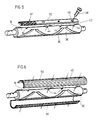
- each gap 42 between the spirally arranged drivers 36 is filled by a driver 36 ′, which is designed as a bar, is straight and runs parallel to the axis of rotation of the roller 18 and is fastened by means of screws 48 penetrating holes 46.
- This driver 36 ' is provided on its surfaces which are not in contact with the roller 18 with the aforementioned covering 40.
- the drivers 36 ' are disassembled and replaced by shell elements 50, which are likewise fastened in the same threaded bores 44 by means of the screws 48.
- Both shell elements 50 are designed as half-shells, which have a radian measure of 180 ° and cover the entire circumference of the roller 18 with the drivers 36 remaining on it.
- the outwardly facing surfaces of the shell elements 50 are covered with the aforementioned covering 40 made of rubber or a rubber or resin mixture.
- the drivers 36 can also be arranged axially offset from one another with respect to the drivers 36 '.
- the advantage of the removable driver 36 'or the shell elements 50 is that the parts provided with the covering 40 can be attached optionally or subsequently.
Landscapes
- Life Sciences & Earth Sciences (AREA)
- Environmental Sciences (AREA)
- Harvesting Machines For Specific Crops (AREA)
- Storage Of Harvested Produce (AREA)
Applications Claiming Priority (2)
| Application Number | Priority Date | Filing Date | Title |
|---|---|---|---|
| DE4019335 | 1990-06-18 | ||
| DE4019335A DE4019335C2 (de) | 1990-06-18 | 1990-06-18 | Ballenpresse zum Bilden zylindrischer Ballen aus einem Erntegut |
Publications (3)
| Publication Number | Publication Date |
|---|---|
| EP0462484A2 true EP0462484A2 (fr) | 1991-12-27 |
| EP0462484A3 EP0462484A3 (en) | 1992-03-18 |
| EP0462484B1 EP0462484B1 (fr) | 1996-01-03 |
Family
ID=6408573
Family Applications (1)
| Application Number | Title | Priority Date | Filing Date |
|---|---|---|---|
| EP91109459A Expired - Lifetime EP0462484B1 (fr) | 1990-06-18 | 1991-06-10 | Presse à balles pour former des balles cylindriques de fourrage |
Country Status (5)
| Country | Link |
|---|---|
| US (1) | US5181461A (fr) |
| EP (1) | EP0462484B1 (fr) |
| CA (1) | CA2044095A1 (fr) |
| DE (2) | DE4019335C2 (fr) |
| DK (1) | DK0462484T3 (fr) |
Cited By (8)
| Publication number | Priority date | Publication date | Assignee | Title |
|---|---|---|---|---|
| EP0954961A1 (fr) * | 1998-05-08 | 1999-11-10 | New Holland Belgium N.V. | Rouleau de formation de balles rondes |
| CN104221589A (zh) * | 2014-08-01 | 2014-12-24 | 黑龙江省畜牧机械化研究所 | 割草压扁机组合式人字形压扁辊 |
| US9205984B2 (en) | 2013-05-23 | 2015-12-08 | Kondex Corporation | Drive roller for baler or other equipment |
| US9686911B2 (en) | 2014-05-12 | 2017-06-27 | Kondex Corporation | Cutting blade with transverse hardened regions |
| US9717176B2 (en) | 2014-09-15 | 2017-08-01 | Kondex Corporation | Agricultural blades and machine parts with amorphous metal laser cladding |
| US9992930B2 (en) | 2014-05-12 | 2018-06-12 | Kondex Corporation | Slicing disc mower knives |
| US10462963B2 (en) | 2012-03-06 | 2019-11-05 | Kondex Corporation | Laser clad cutting edge for agricultural cutting components |
| US10648051B2 (en) | 2015-04-24 | 2020-05-12 | Kondex Corporation | Reciprocating cutting blade with cladding |
Families Citing this family (22)
| Publication number | Priority date | Publication date | Assignee | Title |
|---|---|---|---|---|
| US5301495A (en) * | 1992-03-12 | 1994-04-12 | Vermeer Manufacturing Company | Unidirectional drum roller for a baler of large cylindrical bales |
| US5691027A (en) | 1993-07-27 | 1997-11-25 | Minnesota Mining And Manufacturing Company | Fastener with a dual purpose cover sheet |
| US5691026A (en) | 1993-07-27 | 1997-11-25 | Minnesota Mining And Manufacturing Company | Fastener member with a dual purpose cover sheet |
| US5749289A (en) * | 1996-10-18 | 1998-05-12 | Hay & Forage Industries | Tall sleeves for round baler drive rolls |
| US6655121B1 (en) | 2000-08-10 | 2003-12-02 | Gehl Company | Powered feed roller system for a round baler |
| DE10045842A1 (de) * | 2000-09-14 | 2002-03-28 | Thomas Schuster | Zuführeinrichtung |
| US6955034B1 (en) * | 2004-07-24 | 2005-10-18 | Cnh America Llc | Crop Conditioner frame with interchangeable rollers |
| DE102006056048A1 (de) | 2006-11-28 | 2008-06-05 | Deere & Company, Moline | Rolle und landwirtschaftlich nutzbare Maschine |
| US20080184691A1 (en) * | 2007-02-01 | 2008-08-07 | Horchler Fred M | Bale forming roller |
| BE1018853A3 (nl) * | 2009-08-10 | 2011-10-04 | Cnh Belgium Nv | Een balenpers met een verbeterde stripper rol. |
| US8429881B2 (en) | 2009-09-18 | 2013-04-30 | Agco Corporation | Baler starter roll |
| CA2734475C (fr) * | 2011-03-16 | 2012-10-09 | Macdon Industries Ltd. | Rouleau d'entrainement de convoyeur a toile d'une tete de moissonneuse-batteuse |
| EP2537407B1 (fr) * | 2011-06-21 | 2013-12-25 | Usines Claas France S.A.S | Rouleau pour presse agricole à balles |
| EP2537408B1 (fr) * | 2011-06-21 | 2016-11-09 | Usines Claas France S.A.S | Rouleau pour une presse à bales agricole |
| BR112015002224A2 (pt) * | 2012-08-02 | 2017-07-04 | Bp Corp North America Inc | mecanismo de alimentação para permitir a alimentação positiva de canas de energia em um mecanismo de corte |
| GB2529381A (en) * | 2014-06-20 | 2016-02-24 | Kuhn Geldrop Bv | Baler apparatus |
| DE102015208675A1 (de) * | 2015-05-11 | 2016-11-17 | Deere & Company | Landwirtschaftliche Rundballenpresse |
| US11154014B2 (en) * | 2019-08-06 | 2021-10-26 | Cnh Industrial America Llc | Agricultural baler with segmented roll |
| US11503770B2 (en) * | 2019-09-23 | 2022-11-22 | Cnh Industrial America Llc | Agricultural baler with looped roll |
| US20220061222A1 (en) * | 2020-09-02 | 2022-03-03 | Deere & Company | Crop stop for bale roll |
| DE102021112210A1 (de) * | 2021-05-11 | 2022-11-17 | Deere & Company | Schneckenförderer und Presse |
| DE202021106050U1 (de) | 2021-11-04 | 2023-02-13 | Grimme Landmaschinenfabrik Gmbh & Co. Kg | Walze für eine landwirtschaftliche Fördervorrichtung, Fördervorrichtung und landwirtschaftliche Arbeitsmaschine |
Family Cites Families (18)
| Publication number | Priority date | Publication date | Assignee | Title |
|---|---|---|---|---|
| US710102A (en) * | 1902-01-09 | 1902-09-30 | Albert F Jones | Operating-roll for leather-working machines. |
| US1568401A (en) * | 1923-07-18 | 1926-01-05 | Charles R Griffith | Roll for carrying fabric conveyer belts of paper-making machines |
| US1660538A (en) * | 1924-09-26 | 1928-02-28 | Goodrich Co B F | Roll for paper-making machines and method of making same |
| US2121925A (en) * | 1938-01-24 | 1938-06-28 | Oczko Marion Keith | Unhairing roll |
| US2921426A (en) * | 1958-01-17 | 1960-01-19 | Int Harvester Co | Crop crushing device with laminated rubber impregnated fibre disc crushing rolls |
| US3132459A (en) * | 1962-05-22 | 1964-05-12 | Int Harvester Co | Auger shroud for hay baler |
| DE1582555A1 (de) * | 1966-04-04 | 1970-05-14 | Case Co J I | Verfahren und Vorrichtung zum Verdichten von Fasermaterialien |
| GB1311655A (en) * | 1969-05-30 | 1973-03-28 | Sperry Rand Ltd | Crop-harvesting machinery |
| US4172354A (en) * | 1977-01-28 | 1979-10-30 | Vermeer Manufacturing Company | Machine for forming large round bales of crop material |
| US4198804A (en) * | 1978-08-08 | 1980-04-22 | Gebr. Claas Maschinenfabrik Gmbh | Round baler machine |
| US4422373A (en) * | 1981-08-31 | 1983-12-27 | Hesston Corporation | Throat control apparatus in an open throat, rotary baler |
| US4426926A (en) * | 1981-09-15 | 1984-01-24 | Deere & Company | Belt for round baler |
| US4428282A (en) * | 1982-05-28 | 1984-01-31 | Deere & Company | Cylindrical baler with self-cleaning drive roller |
| EP0151665B1 (fr) * | 1984-02-15 | 1987-05-27 | Deere & Company | Presse à balles rondes |
| US4510741A (en) * | 1984-03-19 | 1985-04-16 | Gehl Company | Rotary crop baler |
| GB2191998A (en) * | 1986-06-26 | 1987-12-31 | Pilkington Brothers Plc | Heat strengthened glass |
| US4782652A (en) * | 1987-09-29 | 1988-11-08 | Hay And Forage Corporation | Round baler having anti-plugging means |
| US4910949A (en) * | 1989-01-17 | 1990-03-27 | Vermeer Manufacturing Co. | Crop material guide means in a machine for forming cylindrical bales |
-
1990
- 1990-06-18 DE DE4019335A patent/DE4019335C2/de not_active Expired - Fee Related
-
1991
- 1991-05-20 US US07/702,563 patent/US5181461A/en not_active Expired - Lifetime
- 1991-06-07 CA CA002044095A patent/CA2044095A1/fr not_active Abandoned
- 1991-06-10 EP EP91109459A patent/EP0462484B1/fr not_active Expired - Lifetime
- 1991-06-10 DE DE59107190T patent/DE59107190D1/de not_active Expired - Fee Related
- 1991-06-10 DK DK91109459.7T patent/DK0462484T3/da active
Cited By (9)
| Publication number | Priority date | Publication date | Assignee | Title |
|---|---|---|---|---|
| EP0954961A1 (fr) * | 1998-05-08 | 1999-11-10 | New Holland Belgium N.V. | Rouleau de formation de balles rondes |
| US10462963B2 (en) | 2012-03-06 | 2019-11-05 | Kondex Corporation | Laser clad cutting edge for agricultural cutting components |
| US9205984B2 (en) | 2013-05-23 | 2015-12-08 | Kondex Corporation | Drive roller for baler or other equipment |
| US9686911B2 (en) | 2014-05-12 | 2017-06-27 | Kondex Corporation | Cutting blade with transverse hardened regions |
| US9992930B2 (en) | 2014-05-12 | 2018-06-12 | Kondex Corporation | Slicing disc mower knives |
| US10206331B2 (en) | 2014-05-12 | 2019-02-19 | Kondex Corporation | Cutting blade with hardened regions |
| CN104221589A (zh) * | 2014-08-01 | 2014-12-24 | 黑龙江省畜牧机械化研究所 | 割草压扁机组合式人字形压扁辊 |
| US9717176B2 (en) | 2014-09-15 | 2017-08-01 | Kondex Corporation | Agricultural blades and machine parts with amorphous metal laser cladding |
| US10648051B2 (en) | 2015-04-24 | 2020-05-12 | Kondex Corporation | Reciprocating cutting blade with cladding |
Also Published As
| Publication number | Publication date |
|---|---|
| EP0462484A3 (en) | 1992-03-18 |
| EP0462484B1 (fr) | 1996-01-03 |
| CA2044095A1 (fr) | 1991-12-19 |
| DE4019335A1 (de) | 1991-12-19 |
| DK0462484T3 (da) | 1996-05-13 |
| DE59107190D1 (de) | 1996-02-15 |
| DE4019335C2 (de) | 1993-11-25 |
| US5181461A (en) | 1993-01-26 |
Similar Documents
| Publication | Publication Date | Title |
|---|---|---|
| EP0462484B1 (fr) | Presse à balles pour former des balles cylindriques de fourrage | |
| EP0803184B1 (fr) | Ramasseur | |
| DE69709981T2 (de) | Rundballenpresse | |
| DE3525754A1 (de) | Erntekopf fuer eine maehmaschine | |
| EP0651940B2 (fr) | Dent à ressort, dispositif convoyeur et moissonneuse | |
| DE69308059T2 (de) | Walzenabstreifeinrichtung für eine Rundballenpresse | |
| EP0651939A1 (fr) | Strippeur pour dispositif convoyeur sur une moissonneuse | |
| EP0535532A2 (fr) | Procédé et dispositif pour lier des balles de récolte | |
| CH667179A5 (de) | Rundballenpresse fuer erntegut. | |
| DE2656896C2 (de) | Rollballenpresse für landwirtschaftliche Halmgüter | |
| EP3482625B1 (fr) | Dispositif de guidage et presse à balles | |
| DE69631089T2 (de) | Erntemaschine | |
| EP0095690B1 (fr) | Presse à balles rondes dont la chambre de compactage comprend une entrée pour le matériau | |
| DE3854411T2 (de) | Rundballenpresse mit Rollen und Riemen. | |
| EP3593623B1 (fr) | Machine de récolte doté d'un dispositif de ramassage de récolte | |
| DE3128104C2 (de) | Rollballenpresse für landwirtschaftliche Halmgüter | |
| EP3300585B1 (fr) | Presse à balles rondes permettant la réception et le pressage de la récolte agricole | |
| DE102021106061A1 (de) | Fördervorrichtung für eine ballenpresse | |
| EP1518455B1 (fr) | Presse à balles rondes | |
| EP0850558B1 (fr) | Presse enrouleuse à courroies | |
| EP4088562B1 (fr) | Presse avec transporteur à vis sans fin | |
| DE4019337C2 (fr) | ||
| EP4039080B1 (fr) | Presse a balles | |
| DE102019006252B4 (de) | Antriebsanordnung für eine Rundballenpresse und Rundballenpresse mit der Antriebsanordnung | |
| EP4442110A1 (fr) | Presse à balles rondes |
Legal Events
| Date | Code | Title | Description |
|---|---|---|---|
| PUAI | Public reference made under article 153(3) epc to a published international application that has entered the european phase |
Free format text: ORIGINAL CODE: 0009012 |
|
| AK | Designated contracting states |
Kind code of ref document: A2 Designated state(s): DE DK ES FR GB IT NL SE |
|
| PUAL | Search report despatched |
Free format text: ORIGINAL CODE: 0009013 |
|
| AK | Designated contracting states |
Kind code of ref document: A3 Designated state(s): DE DK ES FR GB IT NL SE |
|
| 17P | Request for examination filed |
Effective date: 19920909 |
|
| 17Q | First examination report despatched |
Effective date: 19930909 |
|
| GRAA | (expected) grant |
Free format text: ORIGINAL CODE: 0009210 |
|
| AK | Designated contracting states |
Kind code of ref document: B1 Designated state(s): DE DK ES FR GB IT NL SE |
|
| PG25 | Lapsed in a contracting state [announced via postgrant information from national office to epo] |
Ref country code: IT Free format text: LAPSE BECAUSE OF FAILURE TO SUBMIT A TRANSLATION OF THE DESCRIPTION OR TO PAY THE FEE WITHIN THE PRESCRIBED TIME-LIMIT;WARNING: LAPSES OF ITALIAN PATENTS WITH EFFECTIVE DATE BEFORE 2007 MAY HAVE OCCURRED AT ANY TIME BEFORE 2007. THE CORRECT EFFECTIVE DATE MAY BE DIFFERENT FROM THE ONE RECORDED. Effective date: 19960103 Ref country code: ES Free format text: THE PATENT HAS BEEN ANNULLED BY A DECISION OF A NATIONAL AUTHORITY Effective date: 19960103 |
|
| GBT | Gb: translation of ep patent filed (gb section 77(6)(a)/1977) |
Effective date: 19960105 |
|
| REF | Corresponds to: |
Ref document number: 59107190 Country of ref document: DE Date of ref document: 19960215 |
|
| ET | Fr: translation filed | ||
| REG | Reference to a national code |
Ref country code: DK Ref legal event code: T3 |
|
| PLBE | No opposition filed within time limit |
Free format text: ORIGINAL CODE: 0009261 |
|
| STAA | Information on the status of an ep patent application or granted ep patent |
Free format text: STATUS: NO OPPOSITION FILED WITHIN TIME LIMIT |
|
| 26N | No opposition filed | ||
| REG | Reference to a national code |
Ref country code: GB Ref legal event code: IF02 |
|
| PGFP | Annual fee paid to national office [announced via postgrant information from national office to epo] |
Ref country code: SE Payment date: 20050621 Year of fee payment: 15 |
|
| PGFP | Annual fee paid to national office [announced via postgrant information from national office to epo] |
Ref country code: DK Payment date: 20050623 Year of fee payment: 15 |
|
| PGFP | Annual fee paid to national office [announced via postgrant information from national office to epo] |
Ref country code: DE Payment date: 20060519 Year of fee payment: 16 |
|
| PG25 | Lapsed in a contracting state [announced via postgrant information from national office to epo] |
Ref country code: SE Free format text: LAPSE BECAUSE OF NON-PAYMENT OF DUE FEES Effective date: 20060611 |
|
| PGFP | Annual fee paid to national office [announced via postgrant information from national office to epo] |
Ref country code: NL Payment date: 20060624 Year of fee payment: 16 |
|
| PGFP | Annual fee paid to national office [announced via postgrant information from national office to epo] |
Ref country code: GB Payment date: 20060626 Year of fee payment: 16 |
|
| PG25 | Lapsed in a contracting state [announced via postgrant information from national office to epo] |
Ref country code: DK Free format text: LAPSE BECAUSE OF NON-PAYMENT OF DUE FEES Effective date: 20060630 |
|
| REG | Reference to a national code |
Ref country code: DK Ref legal event code: EBP |
|
| EUG | Se: european patent has lapsed | ||
| GBPC | Gb: european patent ceased through non-payment of renewal fee |
Effective date: 20070610 |
|
| NLV4 | Nl: lapsed or anulled due to non-payment of the annual fee |
Effective date: 20080101 |
|
| PG25 | Lapsed in a contracting state [announced via postgrant information from national office to epo] |
Ref country code: NL Free format text: LAPSE BECAUSE OF NON-PAYMENT OF DUE FEES Effective date: 20080101 Ref country code: DE Free format text: LAPSE BECAUSE OF NON-PAYMENT OF DUE FEES Effective date: 20080101 |
|
| PGFP | Annual fee paid to national office [announced via postgrant information from national office to epo] |
Ref country code: FR Payment date: 20070618 Year of fee payment: 17 |
|
| PG25 | Lapsed in a contracting state [announced via postgrant information from national office to epo] |
Ref country code: GB Free format text: LAPSE BECAUSE OF NON-PAYMENT OF DUE FEES Effective date: 20070610 |
|
| REG | Reference to a national code |
Ref country code: FR Ref legal event code: ST Effective date: 20090228 |
|
| PG25 | Lapsed in a contracting state [announced via postgrant information from national office to epo] |
Ref country code: FR Free format text: LAPSE BECAUSE OF NON-PAYMENT OF DUE FEES Effective date: 20080630 |