EP0462694A2 - Schutzvorrichtung gegen zeitliche Systemüberspannungen - Google Patents
Schutzvorrichtung gegen zeitliche Systemüberspannungen Download PDFInfo
- Publication number
- EP0462694A2 EP0462694A2 EP91303695A EP91303695A EP0462694A2 EP 0462694 A2 EP0462694 A2 EP 0462694A2 EP 91303695 A EP91303695 A EP 91303695A EP 91303695 A EP91303695 A EP 91303695A EP 0462694 A2 EP0462694 A2 EP 0462694A2
- Authority
- EP
- European Patent Office
- Prior art keywords
- voltage
- block
- line
- overvoltage protection
- ground
- Prior art date
- Legal status (The legal status is an assumption and is not a legal conclusion. Google has not performed a legal analysis and makes no representation as to the accuracy of the status listed.)
- Withdrawn
Links
Images

Classifications
-
- H—ELECTRICITY
- H02—GENERATION; CONVERSION OR DISTRIBUTION OF ELECTRIC POWER
- H02H—EMERGENCY PROTECTIVE CIRCUIT ARRANGEMENTS
- H02H9/00—Emergency protective circuit arrangements for limiting excess current or voltage without disconnection
- H02H9/04—Emergency protective circuit arrangements for limiting excess current or voltage without disconnection responsive to excess voltage
-
- H—ELECTRICITY
- H02—GENERATION; CONVERSION OR DISTRIBUTION OF ELECTRIC POWER
- H02H—EMERGENCY PROTECTIVE CIRCUIT ARRANGEMENTS
- H02H9/00—Emergency protective circuit arrangements for limiting excess current or voltage without disconnection
- H02H9/04—Emergency protective circuit arrangements for limiting excess current or voltage without disconnection responsive to excess voltage
- H02H9/041—Emergency protective circuit arrangements for limiting excess current or voltage without disconnection responsive to excess voltage using a short-circuiting device
Definitions
- the present invention relates generally to energy absorption devices such as high voltage surge arresters capable of limiting voltages, and more particularly to a surge arrester apparatus and method capable of absorbing high energy dosages resulting from temporary system overvoltages ranging in duration up to a few seconds.
- Temporary system overvoltages may occur as a result of a variety of conditions. For example, a ground fault produces an undamped overvoltage on the unfaulted phases, of a 3-phase high voltage transmission system which must be removed through appropriate switching action. If the voltage is high enough, this may cause saturation in transformers, causing harmonics. A sudden load change (load rejection in the worst case) may cause a voltage rise at the generator which, when combined with Ferranti effect, causes an increase on the line voltage; Ferroresonance in cable connected transformers; dynamic overvoltages on the ac side caused by blocking action at an HVDC converter station, and the like. It is highly desirable that effective means be provided to protect electrical insulation systems against temporary overvoltages ranging in a time duration up to several seconds.
- Surge arresters are generally known in the art which satisfactorily protect electrical power systems from transient overvoltages ranging in duration from a few microseconds to a few milliseconds.
- Conventional prior art surge arresters are incapable of limiting the overvoltages to the levels of 1.1 to 1.2 per unit; also they are incapable of absorbing the prolonged high energy dosages resulting from temporary overvoltages of up to several seconds.
- surge arresters utilizing silicon carbide materials are known, but they are generally limited in their capabilities due to the relatively low degree of non-linearity in their volt-ampere (V-I) characteristics.
- U.S. Patent 1,850,507 teaches a current by-pass for obtaining a constant voltage from a circuit subject to voltage fluctuations for protection against overvoltages.
- U.S. Patent 3,551,745 discloses a silicon control rectifier (SCR) connected across the shunt regulator and a load to short the regulator output when the regulator output voltage exceeds a nominal level.
- SCR silicon control rectifier
- U.S. Patent 4,322,767 teaches bi-directional solid-state circuitry using gated diode switches.
- the circuitry includes zenor diodes, resistors, capacitors and gated diodes arranged to perform a voltage overload protection function independent of the polarity of the overload and independent of which of the terminals experiences the overload.
- U.S. Patent 4,297,739 teaches a circuit for preventing overvoltages in the exciting winding of a synchronous machine.
- U.S. Patent 4,321,644 teaches a power line transient limiter for providing overvoltage protection in commercial airplanes.
- the transient limiter includes a relatively complex arrangement of current-steering diodes, current-limiting resistors, capacitors to reduce the rate of voltage rise, and the like.
- U.S. Patent 3,375,405 discloses a circuit capable of momentarily shunting voltage surges from the line by connecting a negative current-resistor in series with a pair of gate-controlled rectifiers.
- This surge protection device requires an inductor coil to limit the rate of current buildup, which is not an effective way of limiting steep wave voltage fronts routinely encountered on a power system.
- Metal-oxide non-linear resistors, and particularly zinc-oxide based ceramics have been developed for use in surge arrester applications. Due to the relatively high degree of non-linearity in the V-I characteristic of zinc-oxide based materials, they can be applied without any series gaps and thus provide improved surge protection and reliability.
- the development and application of zinc-oxide based materials for use in surge arresters for overvoltage protection is described in "Development of a New Type of Nonlinear Resistance Valve Block for Surge Arresters", Electric Power Research Institute Final Report EPRI EL-1647, Project 425-1, December, 1980.
- Gapless surge arrester poles utilizing zinc oxide based ceramic materials have been assembled and tested for 550 kV and 1200 kV systems.
- One complete 550 kV pole was designed as an assembly of three porcelain units attached in a single column, complete with grading and corona rings. Based on the maximum line to ground voltage of 318 kV, each porcelain unit was rated at 106 kV maximum continuous operating voltage.
- Gapless arresters are conventionally designed to operate at a line voltage V0 which is approximately 80 to 85% of the critical crossover voltage V c .
- Present gapless arresters clamp line voltage excursions at a protective level (hereinafter PL) of 1.5.
- PL protective level
- Protecting a system to 1.5 PL against transient overvoltages having a duration of several microseconds to several milliseconds is satisfactory for many surge arrester applications. It is desirable however to protect a power system from temporary overvoltages having a duration on the order of up to several seconds and a PL in the range of 1.1 to 1.2.
- An object of an embodiment of the present invention is to provide such a device which is capable of absorbing high energy dosages ranging in duration from one cycle several cycles and up to a time duration of several seconds.
- Another objective of an embodiment is to meet the thermal energy requirements of a high voltage transmission system at a protective level of about 1.1 to 1.2 per unit of maximum line to ground voltage.
- a surge arrester for grounding temporary overvoltages in a power system.
- the apparatus and method include a voltage divider having a first varistor block and a second varistor block electrically connected in series.
- the first block and the second block each include a plurality of varistors.
- the first block and second block each exist in an essentially nonconductive mode under normal voltage operation of the power system.
- a thyristor circuit having a voltage sensor and a trigger responsive to the sensor are electrically connected between the first and second blocks.
- the voltage sensor continuously senses line voltage V o , and compares the sensed voltage V o with a predetermined protection voltage of magnitude V p . When the V o reaches a predetermined threshold value the thyristors are switched on shorting out the second set of blocks, thus increasing the voltage across the first set of blocks. This voltage exceeds V c and current conduction and energy absorption starts.
- the thyristor circuit further comprises a pair of oppositely coupled thyristors electrically connected in parallel with respect to each other.
- the thyristor pair is connected between the output of the first block and ground.
- the predetermined threshold value is approximately 1.1 or 1.2 PU.
- the second group of varistors do not perform any varistor function other than acting as a voltage divider defining the portion of the line voltage surge absorbed by the first varistor block.
- a low cost capacitor with substantially identical impedance characteristics is substituted for the second block.
- a voltage divider comprising a first varistor block 12 and a second varistor block 13 are connected in series between line voltage V o 14 and ground.
- a pair of oppositely coupled thyristors 15 and 16 are electrically connected in parallel with respect to each other. The thyristor pair 15 and 16 is connected between the output of the first block and ground.
- the first varistor block 12 and the second varistor block 13 should maintain high impedance characteristics during non-conductive mode, and high energy absorbing characteristics during conductive mode.
- the varistor blocks should include a metal oxide varistor type, with zinc oxide as a major component.
- metal oxide constituents include, but are not limited to: Bi2O3, Sb2O3, Co3O4, MnO2 NiO, Cr2O3, Al2O3, Ga2O3 and ZrO2.
- the varistor block 12 exists in two states; a non-conductive mode and a conductive mode.
- the blocks 12 and 13 act as current insulators and permit only minimal current leakage through the blocks.
- the number of zinc-oxide varistor discs needed to sustain the voltage can be calculated.
- a varistor block 1cm tall will have a critical voltage (V c ) of 2 to 3 kV (kV - 1000V) e.g. for a 550kV three phase AC system, the line-to-ground peak voltage would be 450kV. So one can use 150 blocks each with a (V c ) rating of 3kV. But such a design will end up always operating at the threshold of conduction, going off from and back into conduction mode, jeopardizing the life of the arresters.
- a preferred approach is to add 20% additional blocks and have an arrestor with 180 blocks.
- V o operating voltage
- the characteristics of the zinc-oxide varistor blocks is such (FIG 2) that when the arrestor is conducting significant current (I L ), the corresponding voltage may be 30% above V c . But since the arrestor operates at V o , with reference to this protection level, the arrestor's ability to limit the voltage is at best 150%. This is unacceptable for some applications.
- a back-to-back thyristor bridge 15, 16 (electrically the thyristors work similar to SCR's) is connected at the junction which is triggered by a voltage sensing device connected to line 14. Thyristor action essentially shorts out an appropriate segment 13 of zinc oxide blocks.
- the device may short out segment 13 of 40 blocks, leaving only segment 12 of 140 blocks connected to line 14, thus putting each block of segment 12 at a voltage of (450kV/140 blocks) 3.21kV. This is above V c and the voltage drop corresponding to leakage current (I L ) (see FIG 2) is made closer to V o , thereby making the device more effective.
- FIG 1 shows a zinc oxide block stack electrically divided into two sectors or segments 12, 13.
- the junction 11 between segments 12 and 13 is where the thyristor bridge (4) is connected.
- This bridge is fired by device 23 or 24 which receives its voltage input from the firing control circuit 25. Since the voltage sensing is required for many other needs on the power system, this function may be available independent of this device and therefore, one can avoid the cost of introducing a voltage transformer for this device.
- FIG 2 shows the electrical characteristics of typical zinc oxide materials. All zinc oxide varistors have a critical voltage (V c ) at which the device which has thus far been behaving essentially as an insulator to electrical current, suddenly turns into a conductor. As it carries more current, it has an increased voltage drop across it as indicated by the slope of the curve.
- V c critical voltage
- the device is operated at V o voltage and if the thyristor switching did not take place, the V/I characteristic would follow the dotted line.
- the switching of a thyristor eliminates a section of zinc oxide blocks (identified as segment 13) and increases the voltage appearing across each block of section or segment 12, and thereby improves the protection.
- the voltage division ratio of sector 12 may range between about 60% to about 80% of the line voltage V o 14.
- the voltage dimension ratio of sector 12 is set at 80% and sector 13's voltage ratio is set at 20% according to one embodiment according to the invention. This is accomplished by adjusting the number of varistors in sector 12 and sector 13 so that sector 12's voltage drop across 12 is four times greater than across section 13.
- the voltage-ampere characteristics of the varistors of block 12 are hereinafter discussed in conjunction with FIG 2.
- a thyristor bridge circuit 4 is electrically connected at the junction 11 of first varistor sector 12 and second varistor sector 13, the other end of bridge circuit 4 being connected to ground.
- the circuit for firing the thyristors 15, 16 incorporated in bridge 4 includes a voltage sensor 21 electrically connected to continuously sense line voltage V o 14; and a firing control circuit 25, electrically connected to the voltage sensor 21 and thyristor bridge 4 for tracking the sensed line voltage V o 14 for a predetermined protection voltage V p .
- the firing control circuit 25 is responsive to the voltage V o ; that is, when a predetermined PC of approximately 1.1 or 1.2 is reached, the control circuit (25) will send the electrical firing pulses to fire thyristors 15 and 16.
- V1/V2 the ratio between V1/V2 is always a constant as long as the thyristors are not conducting current. In effect, they become a voltage divider. If V2 is monitored, (which is smaller and one end is grounded and, therefore, easy to monitor) V1 and V o can be calculated. When V o goes up, V2 goes up in the ratio. Therefore, when an increase in V2 by a factor of 1.1 to 1.2 is seen, whichever is the set threshold, thyristors 13, 14 start conducting, bringing about the desired operation. This reduces the insulation ratings of the voltage measurement circuit and makes the invention more valuable.
- the current flow through the varistor section 12 is primarily a function of the energy levels being dissipated, which determines the current density flow.
- the varistor blocks of each section display the following voltage-ampere characteristics during line operation.
- the current flow through the varistor block 12 is minimal a few milliamperes, and is limited to leakage current at normal voltage.
- the ampere curve of FIG 2 is substantially vertical for line voltages V o less than V c .
- the surge arrester 10 protects from temporary system overvoltages ranging in duration of up to a few seconds because of the line surge voltage dividing capabilities of the blocks 12 and 13 and the increased energy absorbing capabilities of varistor block 12. Effectively through the thyristor switching, a lower (improved) protective characteristic is achieved by setting the crossover voltage V p close to the normal operating line voltage V o 14, and yet long life of the device is ensured by exposing the varistor blocks to lower voltages under normal operation.
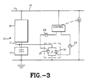
- FIG 3 a second embodiment of the present invention is shown.
- the second block 13 of FIG 1 is replaced by an equivalent capacity capacitor 17.
- Block 13 may be replaced by capacitor 17 because block 17 does not dissipate line voltage surges as does block 13. Accordingly, a capacitor with substantially the same impedance characteristics may be substituted for block 13.
- Capacitor 17 provides a relatively inexpensive voltage dividing circuit for limiting the line voltage V o 14 dissipation across varistor block 12. With an impedance substantially equivalent to varistor block 13 in the preferred embodiment of FIG 1, 100% of the line voltage V o 14 is dissipated in the first varistor block during line surge voltage conditions.
- the present invention is not intended to be limited solely to use with varistors made of such materials.
Landscapes
- Emergency Protection Circuit Devices (AREA)
- Medicines That Contain Protein Lipid Enzymes And Other Medicines (AREA)
Applications Claiming Priority (2)
| Application Number | Priority Date | Filing Date | Title |
|---|---|---|---|
| US54158190A | 1990-06-21 | 1990-06-21 | |
| US541581 | 1990-06-21 |
Publications (2)
| Publication Number | Publication Date |
|---|---|
| EP0462694A2 true EP0462694A2 (de) | 1991-12-27 |
| EP0462694A3 EP0462694A3 (en) | 1992-10-14 |
Family
ID=24160189
Family Applications (1)
| Application Number | Title | Priority Date | Filing Date |
|---|---|---|---|
| EP19910303695 Withdrawn EP0462694A3 (en) | 1990-06-21 | 1991-04-24 | Protective device for temporary system overvoltages |
Country Status (2)
| Country | Link |
|---|---|
| EP (1) | EP0462694A3 (de) |
| CA (1) | CA2040163A1 (de) |
Cited By (31)
| Publication number | Priority date | Publication date | Assignee | Title |
|---|---|---|---|---|
| WO2011023238A1 (en) * | 2009-08-31 | 2011-03-03 | Abb Technology Ag | A method and a device for overvoltage protection, and an electric system with such a device |
| WO2011098145A1 (en) * | 2010-02-12 | 2011-08-18 | Abb Research Ltd | An arrangement for protecting a solid-state dc-breaker against transient voltages |
| EP2523296A1 (de) * | 2011-05-11 | 2012-11-14 | Siemens Aktiengesellschaft | Schaltungsanordnung zum Bereitstellen eines Überspannungsschutzes und Verfahren zu deren Betrieb |
| EP2549613A1 (de) * | 2011-07-19 | 2013-01-23 | Hamilton Sundstrand Corporation | Überspannungsschutzverfahren und -vorrichtung |
| CN103269061A (zh) * | 2013-05-29 | 2013-08-28 | 安徽通辰电气有限公司 | 可变阻抗的避雷器防老化保护装置 |
| WO2014079508A1 (en) | 2012-11-23 | 2014-05-30 | Abb Technology Ltd | An ac temporary load device and distribution system for operating an electric machine or electrical load powered by a long cable |
| WO2016166697A3 (en) * | 2015-04-15 | 2016-11-24 | COSTRUZIONI ELETTROMECCANICHE P. TORRESAN S.r.l. | Voltage shunt regulator for the protection of an electrical load from overvoltages and voltage transients. |
| EP3211644A1 (de) * | 2016-02-26 | 2017-08-30 | Siemens Aktiengesellschaft | Überspannungsableiter mit mitteln zum messen transienter überspannungen |
| EP3206289A4 (de) * | 2014-10-08 | 2018-05-30 | Mitsubishi Electric Corporation | Stromwandlungsvorrichtung |
| EP3340411A1 (de) * | 2016-12-23 | 2018-06-27 | RIPD Research and IP Development Ltd. | Vorrichtungen für aktiven überspannungsschutz |
| WO2018167716A1 (en) * | 2017-03-15 | 2018-09-20 | Saltek S.R.O. | Voltage limiter with overvoltage protection |
| CZ307538B6 (cs) * | 2013-02-06 | 2018-11-21 | Saltek S.R.O. | Zapojení hybridního omezovače napětí a přepěťové ochrany |
| US10679814B2 (en) | 2017-05-12 | 2020-06-09 | Raycap IP Development Ltd | Surge protective device modules including integral thermal disconnect mechanisms and methods including same |
| US10685767B2 (en) | 2017-09-14 | 2020-06-16 | Raycap IP Development Ltd | Surge protective device modules and systems including same |
| WO2020120327A1 (en) * | 2018-12-14 | 2020-06-18 | Signify Holding B.V. | Provisional overvoltage protection for a luminaire |
| US10707678B2 (en) | 2016-12-23 | 2020-07-07 | Ripd Research And Ip Development Ltd. | Overvoltage protection device including multiple varistor wafers |
| US10734176B2 (en) | 2016-11-30 | 2020-08-04 | Raycap, Surge Protective Devices, Ltd. | Surge protective device modules and DIN rail device systems including same |
| WO2020233180A1 (zh) * | 2019-05-21 | 2020-11-26 | 南京南瑞继保电气有限公司 | 限流型可控避雷器、换流器、输电系统以及控制方法 |
| US11223200B2 (en) | 2018-07-26 | 2022-01-11 | Ripd Ip Development Ltd | Surge protective devices, circuits, modules and systems including same |
| CN114447897A (zh) * | 2020-11-06 | 2022-05-06 | Abb瑞士股份有限公司 | 功率半导体开关钳位电路 |
| US11723145B2 (en) | 2021-09-20 | 2023-08-08 | Raycap IP Development Ltd | PCB-mountable surge protective device modules and SPD circuit systems and methods including same |
| US11862967B2 (en) | 2021-09-13 | 2024-01-02 | Raycap, S.A. | Surge protective device assembly modules |
| IT202200022149A1 (it) * | 2022-10-27 | 2024-04-27 | Asteco Impianti S R L | Dispositivo di protezione dalle sovratensioni per utenze elettriche |
| US11990745B2 (en) | 2022-01-12 | 2024-05-21 | Raycap IP Development Ltd | Methods and systems for remote monitoring of surge protective devices |
| US12199412B2 (en) | 2022-06-02 | 2025-01-14 | Ripd Ip Development Ltd. | Surge protective devices, circuits, modules and systems including same |
| US12206234B2 (en) | 2022-09-20 | 2025-01-21 | Ripd Ip Development Ltd | Overvoltage protection device modules |
| CN119846516A (zh) * | 2025-03-18 | 2025-04-18 | 国网湖北送变电工程有限公司 | 一种自动检测加载限流电阻的避雷器检测方法 |
| US12437906B2 (en) | 2022-10-18 | 2025-10-07 | Raycap, S.A. | Surge protective devices |
| US12506334B2 (en) | 2022-01-24 | 2025-12-23 | Raycap IP Development Ltd | Surge protective device modules and assemblies |
| US12580381B2 (en) | 2023-12-04 | 2026-03-17 | Ripd Ip Development Ltd | Overvoltage protection device modules and sheath bonding systems including same |
| EP4723411A1 (de) * | 2024-10-04 | 2026-04-08 | Schneider Electric Industries Sas | Minimal- oder spannungsmangel-nebenschlussauslöser für einen schutzschalter, zugehörige anordnung und verfahren |
Families Citing this family (1)
| Publication number | Priority date | Publication date | Assignee | Title |
|---|---|---|---|---|
| CN110829372B (zh) * | 2019-11-11 | 2024-10-18 | 广西电网有限责任公司电力科学研究院 | 一种智能抗、消谐pt综合防护装置及其防护方法 |
Family Cites Families (2)
| Publication number | Priority date | Publication date | Assignee | Title |
|---|---|---|---|---|
| DE1513491B2 (de) * | 1965-07-16 | 1971-10-28 | Siemens AG, 1000 Berlin u. 8000 München | Schaltung zur begrenzung hoher gleichspannungen |
| US4912589A (en) * | 1988-01-13 | 1990-03-27 | Tii Industries, Inc. | Surge suppression on AC power lines |
-
1991
- 1991-04-10 CA CA 2040163 patent/CA2040163A1/en not_active Abandoned
- 1991-04-24 EP EP19910303695 patent/EP0462694A3/en not_active Withdrawn
Cited By (50)
| Publication number | Priority date | Publication date | Assignee | Title |
|---|---|---|---|---|
| US8643995B2 (en) | 2009-08-31 | 2014-02-04 | Abb Technology Ag | Method and a device for overvoltage protection, and an electric system with such a device |
| KR101374968B1 (ko) * | 2009-08-31 | 2014-03-14 | 에이비비 테크놀로지 아게 | 과전압 보호를 위한 방법 및 디바이스, 이러한 디바이스를 가진 전기 시스템 |
| CN102484419B (zh) * | 2009-08-31 | 2015-12-02 | Abb技术有限公司 | 过电压保护方法和设备、及具有如此设备的电力系统 |
| WO2011023238A1 (en) * | 2009-08-31 | 2011-03-03 | Abb Technology Ag | A method and a device for overvoltage protection, and an electric system with such a device |
| WO2011098145A1 (en) * | 2010-02-12 | 2011-08-18 | Abb Research Ltd | An arrangement for protecting a solid-state dc-breaker against transient voltages |
| EP2523296A1 (de) * | 2011-05-11 | 2012-11-14 | Siemens Aktiengesellschaft | Schaltungsanordnung zum Bereitstellen eines Überspannungsschutzes und Verfahren zu deren Betrieb |
| US9537307B2 (en) | 2011-07-19 | 2017-01-03 | Hamilton Sundstrand Corporation | Overvoltage protection method and device |
| EP2549613A1 (de) * | 2011-07-19 | 2013-01-23 | Hamilton Sundstrand Corporation | Überspannungsschutzverfahren und -vorrichtung |
| WO2014079508A1 (en) | 2012-11-23 | 2014-05-30 | Abb Technology Ltd | An ac temporary load device and distribution system for operating an electric machine or electrical load powered by a long cable |
| CZ307538B6 (cs) * | 2013-02-06 | 2018-11-21 | Saltek S.R.O. | Zapojení hybridního omezovače napětí a přepěťové ochrany |
| CN103269061A (zh) * | 2013-05-29 | 2013-08-28 | 安徽通辰电气有限公司 | 可变阻抗的避雷器防老化保护装置 |
| CN103269061B (zh) * | 2013-05-29 | 2018-03-02 | 安徽通辰电气有限公司 | 可变阻抗的避雷器防老化保护装置 |
| EP3206289A4 (de) * | 2014-10-08 | 2018-05-30 | Mitsubishi Electric Corporation | Stromwandlungsvorrichtung |
| WO2016166697A3 (en) * | 2015-04-15 | 2016-11-24 | COSTRUZIONI ELETTROMECCANICHE P. TORRESAN S.r.l. | Voltage shunt regulator for the protection of an electrical load from overvoltages and voltage transients. |
| US10056824B2 (en) | 2015-04-15 | 2018-08-21 | COSTRUZIONI ELETTROMECCANICHE P. TORRESAN S.r.l. | Voltage shunt regulator for the protection of an electrical load from over-voltages and voltage transients |
| EP3211644A1 (de) * | 2016-02-26 | 2017-08-30 | Siemens Aktiengesellschaft | Überspannungsableiter mit mitteln zum messen transienter überspannungen |
| DE102016203109A1 (de) * | 2016-02-26 | 2017-08-31 | Siemens Aktiengesellschaft | Überspannungsableiter mit Mitteln zum Messen transienter Überspannungen |
| US10734176B2 (en) | 2016-11-30 | 2020-08-04 | Raycap, Surge Protective Devices, Ltd. | Surge protective device modules and DIN rail device systems including same |
| US10707678B2 (en) | 2016-12-23 | 2020-07-07 | Ripd Research And Ip Development Ltd. | Overvoltage protection device including multiple varistor wafers |
| US12237664B2 (en) | 2016-12-23 | 2025-02-25 | Ripd Research And Ip Development Ltd. | Devices for active overvoltage protection including varistors and thyristors |
| US10447026B2 (en) | 2016-12-23 | 2019-10-15 | Ripd Ip Development Ltd | Devices for active overvoltage protection |
| US20220399714A1 (en) * | 2016-12-23 | 2022-12-15 | Ripd Research And Ip Development Ltd. | Devices for active overvoltage protection |
| US11374396B2 (en) | 2016-12-23 | 2022-06-28 | Ripd Research And Ip Development Ltd. | Devices for active overvoltage protection |
| CN114583675A (zh) * | 2016-12-23 | 2022-06-03 | Ripd知识产权发展有限公司 | 用于主动过电压保护的装置 |
| CN108242805A (zh) * | 2016-12-23 | 2018-07-03 | Ripd研究与知识产权发展有限公司 | 用于主动过电压保护的装置 |
| EP3340411A1 (de) * | 2016-12-23 | 2018-06-27 | RIPD Research and IP Development Ltd. | Vorrichtungen für aktiven überspannungsschutz |
| US11881704B2 (en) * | 2016-12-23 | 2024-01-23 | Ripd Research And Ip Development Ltd. | Devices for active overvoltage protection including varistors and thyristors |
| US11165246B2 (en) | 2016-12-23 | 2021-11-02 | Ripd Research And Ip Development Ltd. | Overvoltage protection device including multiple varistor wafers |
| CN108242805B (zh) * | 2016-12-23 | 2022-04-15 | Ripd知识产权发展有限公司 | 用于主动过电压保护的装置 |
| US11223198B2 (en) | 2017-03-15 | 2022-01-11 | Saltek S.R.O. | Voltage limiter with overvoltage protection |
| WO2018167716A1 (en) * | 2017-03-15 | 2018-09-20 | Saltek S.R.O. | Voltage limiter with overvoltage protection |
| US10679814B2 (en) | 2017-05-12 | 2020-06-09 | Raycap IP Development Ltd | Surge protective device modules including integral thermal disconnect mechanisms and methods including same |
| US10685767B2 (en) | 2017-09-14 | 2020-06-16 | Raycap IP Development Ltd | Surge protective device modules and systems including same |
| US11223200B2 (en) | 2018-07-26 | 2022-01-11 | Ripd Ip Development Ltd | Surge protective devices, circuits, modules and systems including same |
| WO2020120327A1 (en) * | 2018-12-14 | 2020-06-18 | Signify Holding B.V. | Provisional overvoltage protection for a luminaire |
| WO2020233180A1 (zh) * | 2019-05-21 | 2020-11-26 | 南京南瑞继保电气有限公司 | 限流型可控避雷器、换流器、输电系统以及控制方法 |
| CN114447897A (zh) * | 2020-11-06 | 2022-05-06 | Abb瑞士股份有限公司 | 功率半导体开关钳位电路 |
| US12646932B2 (en) | 2021-09-13 | 2026-06-02 | Raycap, S.A. | Surge protective device assembly modules |
| US11862967B2 (en) | 2021-09-13 | 2024-01-02 | Raycap, S.A. | Surge protective device assembly modules |
| US11723145B2 (en) | 2021-09-20 | 2023-08-08 | Raycap IP Development Ltd | PCB-mountable surge protective device modules and SPD circuit systems and methods including same |
| US11990745B2 (en) | 2022-01-12 | 2024-05-21 | Raycap IP Development Ltd | Methods and systems for remote monitoring of surge protective devices |
| US12506334B2 (en) | 2022-01-24 | 2025-12-23 | Raycap IP Development Ltd | Surge protective device modules and assemblies |
| US12199412B2 (en) | 2022-06-02 | 2025-01-14 | Ripd Ip Development Ltd. | Surge protective devices, circuits, modules and systems including same |
| US12206234B2 (en) | 2022-09-20 | 2025-01-21 | Ripd Ip Development Ltd | Overvoltage protection device modules |
| US12437906B2 (en) | 2022-10-18 | 2025-10-07 | Raycap, S.A. | Surge protective devices |
| IT202200022149A1 (it) * | 2022-10-27 | 2024-04-27 | Asteco Impianti S R L | Dispositivo di protezione dalle sovratensioni per utenze elettriche |
| US12580381B2 (en) | 2023-12-04 | 2026-03-17 | Ripd Ip Development Ltd | Overvoltage protection device modules and sheath bonding systems including same |
| EP4723411A1 (de) * | 2024-10-04 | 2026-04-08 | Schneider Electric Industries Sas | Minimal- oder spannungsmangel-nebenschlussauslöser für einen schutzschalter, zugehörige anordnung und verfahren |
| FR3167260A1 (fr) * | 2024-10-04 | 2026-04-10 | Schneider Electric Industries Sas | Déclencheur shunt à minimum ou manque de tension pour un disjoncteur, ensemble et procédé associés |
| CN119846516A (zh) * | 2025-03-18 | 2025-04-18 | 国网湖北送变电工程有限公司 | 一种自动检测加载限流电阻的避雷器检测方法 |
Also Published As
| Publication number | Publication date |
|---|---|
| EP0462694A3 (en) | 1992-10-14 |
| CA2040163A1 (en) | 1991-12-22 |
Similar Documents
| Publication | Publication Date | Title |
|---|---|---|
| US12237664B2 (en) | Devices for active overvoltage protection including varistors and thyristors | |
| US4174530A (en) | Voltage surge arrester device | |
| US3947726A (en) | Reverse voltage surge protection for high-voltage thyristors | |
| EP0701313B1 (de) | Schutzschalter und Spannungsbegrenzungsschaltung | |
| US4652963A (en) | Series capacitor equipment | |
| US4300181A (en) | Commutation circuit for an HVDC circuit breaker | |
| EP1058366A2 (de) | Überspannungsunterdrückungsschaltung, auf die Änderungsgeschwindigkeit einer Stromstörung reagiert | |
| JPS6022798Y2 (ja) | サイリスタの過電圧保護回路 | |
| US4625254A (en) | Voltage trigger means for a series capacitor protector | |
| US3848156A (en) | Surge arrestor for high voltage electric power applications | |
| JP2011510508A (ja) | 高電圧サージ・アレスター及びそれを動作させる方法 | |
| US3859568A (en) | Overvoltage surge arrester with improved voltage grading circuit | |
| US4890180A (en) | Series capacitor equipment | |
| US12470059B2 (en) | Overvoltage protection device and use of an overvoltage protection device | |
| US4002947A (en) | Arcing stacked plate nonlinear resistor for voltage limiter applications such as series capacitor protection | |
| US4084207A (en) | Adjustable overvoltage protected circuit for high power thyristors | |
| US3743884A (en) | Overvoltage protector | |
| RU2337449C1 (ru) | Устройство защиты оборудования от перенапряжений | |
| US4340921A (en) | HVDC Power transmission system with metallic return conductor | |
| RU207848U1 (ru) | Устройство защиты оборудования от импульсных перенапряжений комбинированного типа | |
| CA1153096A (en) | Commutation circuit for an hvdc circuit breaker | |
| RU194140U1 (ru) | Устройство защиты оборудования от импульсных перенапряжений | |
| CA1056010A (en) | Reverse voltage surge protection for high-voltage thyristors | |
| RU2304835C1 (ru) | Устройство защиты от перенапряжений | |
| SU1078530A1 (ru) | Устройство защиты от перенапр жений |
Legal Events
| Date | Code | Title | Description |
|---|---|---|---|
| PUAI | Public reference made under article 153(3) epc to a published international application that has entered the european phase |
Free format text: ORIGINAL CODE: 0009012 |
|
| AK | Designated contracting states |
Kind code of ref document: A2 Designated state(s): AT BE CH DE DK ES FR GB GR IT LI LU NL SE |
|
| PUAL | Search report despatched |
Free format text: ORIGINAL CODE: 0009013 |
|
| AK | Designated contracting states |
Kind code of ref document: A3 Designated state(s): AT BE CH DE DK ES FR GB GR IT LI LU NL SE |
|
| 17P | Request for examination filed |
Effective date: 19930318 |
|
| STAA | Information on the status of an ep patent application or granted ep patent |
Free format text: STATUS: THE APPLICATION HAS BEEN WITHDRAWN |
|
| 18W | Application withdrawn |
Withdrawal date: 19940412 |