EP0462695A2 - Flammenhalterplatte für Brenner - Google Patents
Flammenhalterplatte für Brenner Download PDFInfo
- Publication number
- EP0462695A2 EP0462695A2 EP91303855A EP91303855A EP0462695A2 EP 0462695 A2 EP0462695 A2 EP 0462695A2 EP 91303855 A EP91303855 A EP 91303855A EP 91303855 A EP91303855 A EP 91303855A EP 0462695 A2 EP0462695 A2 EP 0462695A2
- Authority
- EP
- European Patent Office
- Prior art keywords
- air
- openings
- plate
- retention plate
- flame retention
- Prior art date
- Legal status (The legal status is an assumption and is not a legal conclusion. Google has not performed a legal analysis and makes no representation as to the accuracy of the status listed.)
- Withdrawn
Links
Images
Classifications
-
- F—MECHANICAL ENGINEERING; LIGHTING; HEATING; WEAPONS; BLASTING
- F23—COMBUSTION APPARATUS; COMBUSTION PROCESSES
- F23D—BURNERS
- F23D14/00—Burners for combustion of a gas, e.g. of a gas stored under pressure as a liquid
- F23D14/34—Burners specially adapted for use with means for pressurising the gaseous fuel or the combustion air
- F23D14/36—Burners specially adapted for use with means for pressurising the gaseous fuel or the combustion air in which the compressor and burner form a single unit
-
- F—MECHANICAL ENGINEERING; LIGHTING; HEATING; WEAPONS; BLASTING
- F23—COMBUSTION APPARATUS; COMBUSTION PROCESSES
- F23D—BURNERS
- F23D14/00—Burners for combustion of a gas, e.g. of a gas stored under pressure as a liquid
- F23D14/20—Non-premix gas burners, i.e. in which gaseous fuel is mixed with combustion air on arrival at the combustion zone
- F23D14/22—Non-premix gas burners, i.e. in which gaseous fuel is mixed with combustion air on arrival at the combustion zone with separate air and gas feed ducts, e.g. with ducts running parallel or crossing each other
-
- F—MECHANICAL ENGINEERING; LIGHTING; HEATING; WEAPONS; BLASTING
- F23—COMBUSTION APPARATUS; COMBUSTION PROCESSES
- F23D—BURNERS
- F23D14/00—Burners for combustion of a gas, e.g. of a gas stored under pressure as a liquid
- F23D14/46—Details
- F23D14/72—Safety devices, e.g. operative in case of failure of gas supply
- F23D14/74—Preventing flame lift-off
Definitions
- Previous burner structures have been known to employ a fan-type generator at the end of an air supply tube to impart a swirling action to combustion air to facilitate mixing of air with fuel. Use of this type of structure is unsatisfactory when it is desired to obtain a high backpressure within the air supply tube.
- This feature provides important operating advantages as set forth in copending application Serial Number 07/382,440 filed July 19, 1989 and assigned to a common assignee as the present application.
- the provision of high backpressure within the air supply tube prevents flashback of the flame into the air tube. Additionally, the backpressure actively forces the combustion air through the flame retention plate.
- the flame retention plate of the invention is employed in combustion with an air tube defining an internal air flow path and a pressurized air supply means for providing pressurized air to the air flow path.
- a fuel supply tube extends through the air flow path and includes lateral discharge means in the form of laterally oriented orifices for discharging air into the air flow path.
- a substantially planar flame retention plate is adapted for placement within the air flow path upstream of the lateral discharge orifices provided in the fuel supply tube.
- the flame retention plate includes a plurality of openings therethrough for outletting air from the air flow path, with the openings being arranged in a predetermined pattern and including an inner ring of relatively small openings and a plurality of relatively large outer openings.
- the outer relatively large openings are arranged so as to provide an outer ring of openings adjacent the outer edge of the flame retention plate and an intermediate ring of openings between the outer ring of openings and the inner ring of openings.
- the outer ring of openings and the intermediate ring of openings are preferably arranged in an overlapping staggered pattern to provide interlacing of air flowing therethrough downstream of the plate.
- the means for altering the flow of air through the plate comprises a ramped surface forming a portion of each opening in the intermediate ring of openings for directing air passing therethrough radially outwardly and into the path of air flowing through the outer ring of openings.
- the ramped surface preferably extends between the inlet side of the plate and the outlet side of the plate in a substantially linear fashion providing an outlet having a lesser area than the area of the inlet, forming a restriction at the outlet of the opening.
- the openings in the outer and intermediate rings of openings are preferably provided with means for increasing the velocity of air passing through the openings, which preferably takes the form of a chamfer provided at the inlet and outlet surfaces of the plate at each opening.
- the acceleration of secondary combustion air as it passes through the flame retention plate enhances downstream mixing of the secondary combustion air with primary air-fuel mixture.
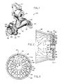
- a power gas burner assembly 10 includes a control box 12, a motor and blower assembly 14, an air tube 16 and an ignition assembly including a burner head assembly 18.
- Blower 14 supplies pressurized air through its outlet to an air duct 26 which has its longitudinal axis disposed at an angle of 45° from the longitudinal axis of air tube 16.
- Air duct 26 communicates pressurized air from blower 14 to the interior of air tube 16.
- Air tube 16 terminates in an end portion 28 providing an angled outwardly flared wall 30, defining a frusto-conical shape to end portion 28 of air tube 16.
- a frusto-conically shaped end extension is adapted for connection to the end of air tube 16 to facilitate assembly of the components of burner 10 shown in FIG. 1.
- a flange 32 is connected to air tube 16 adjacent its discharge end.
- a flange gasket 34 is adapted for placement adjacent flange 32, with a sealing gasket 36 adapted to secure the flared end portion 28 to air tube 16.
- Ignitor 38 and flame sensing rod 40 are connected to a flame retention plate 46 adapted for placement at the discharge of air tube 16.
- flame retention plate 46 includes an upper opening 47 in which ignitor 38 is normally mounted.
- Flame sensing rod 40 is mounted in an opening 48 in retention plate 46.
- retention plate 46 is placed upstream of the flared end wall 30 provided at the end of air tube 16, and gas tube 20 extends through retention plate 46.
- Orifice cap 24 provided at the end of gas tube 20 includes a series of laterally oriented gas discharge orifices, shown at 49, 50, which are oriented perpendicularly to the direction of flow of gas through gas tube 20.
- Air tube 16 defines an internal air flow path 51 to which pressurized air from blower assembly 14 is supplied, and gas tube 20 extends through air flow path 48 in a direction coaxial therewith.
- the longitudinal axes of discharge orifices 49, 50 are oriented perpendicularly to the direction of movement of air through air flow path 51 for discharging gas outwardly into air flow path 51 from the interior of gas tube 20.
- retention plate 46 is placed upstream of the discharge of gas from gas tube 20, acting to enclose the outlet of air tube 16 and to control the flow of air therethrough.
- Flame retention plate 46 has a diameter of 3.845 inches and a thickness of approximately 0.218 inches and, as shown in FIGS. 2 and 3, includes a substantially central opening 50 through which gas tube 20 extends.
- An inner ring of relatively small orifices 52 is provided at the inner portion of retention plate 46, having its center coincident with the longitudinal axis of air tube 16. Inner openings 52 are relatively small in diameter, having an internal diameter of approximately 0.1935 inches.
- Retention plate 46 further includes an intermediate ring of openings 54 having a relatively large diameter, and an outer ring of openings 56 also having a relatively large diameter substantially equal to that of openings 54. Openings 56 and the inlet side of openings 54 each have a diameter of approximately 0.4375 inches. In some applications, it is contemplated that the outer ring of openings 56 may be slightly larger than the intermediate ring of openings 54.
- the intermediate ring of openings 54 and the outer ring of openings 56 are arranged in an overlapping staggered pattern. With this construction, an interlacing of air discharged from internal flow path 51 of air tube 16 is accomplished after air passes through flame retention plate 46.
- This partial vacuum created by the outward deflection of air caused by ramped surfaces 58 additionally results in the air-gas mixture being drawn back towards the center of the flow area, as shown in the arrows representing air and gas flow in FIG. 2, resulting in additional turbulent mixing of air with gas.
- ramped surfaces 58 gas from discharge orifices 49, 50 is dispersed more rapidly to the secondary outer air passing through the intermediate ring of orifices 54 and the outer ring of orifices 56 than would be accomplished if angled surfaces 58 were not present.
- This arrangement provides better gas and air mixing closer to flame retention plate 46, thus providing a shorter flame and more efficient combustion as a result of gas mixing with air quickly and thoroughly close to retention plate 46. Accordingly, a relatively short end portion 28 can be employed.
- Each of openings 54 in the intermediate ring of openings is provided with a chamfer 60 at the inlet side of plate 46 and a chamfer 62 at the outlet side of plate 46.
- each of openings 56 in the outer ring of openings is provided with a chamfer 64 at the inlet side of plate 46 and a chamfer 66 at the outlet side of plate 46. It is believed that chamfers 60-66 act to accelerate air as it passes through openings 54 and 56, while maintaining back pressure within internal flow path 48 of air tube 16. The resulting increase in velocity of air passing through openings 54, 56 provides additional kinetic energy at the area of convergence of air from openings 54 with air from openings 56, thus increasing the efficiency of gas and air mixing.
Landscapes
- Engineering & Computer Science (AREA)
- Chemical & Material Sciences (AREA)
- Combustion & Propulsion (AREA)
- Mechanical Engineering (AREA)
- General Engineering & Computer Science (AREA)
- Gas Burners (AREA)
Applications Claiming Priority (2)
| Application Number | Priority Date | Filing Date | Title |
|---|---|---|---|
| US54007990A | 1990-06-19 | 1990-06-19 | |
| US540079 | 1990-06-19 |
Publications (2)
| Publication Number | Publication Date |
|---|---|
| EP0462695A2 true EP0462695A2 (de) | 1991-12-27 |
| EP0462695A3 EP0462695A3 (en) | 1992-03-11 |
Family
ID=24153902
Family Applications (1)
| Application Number | Title | Priority Date | Filing Date |
|---|---|---|---|
| EP19910303855 Withdrawn EP0462695A3 (en) | 1990-06-19 | 1991-04-29 | Flame retention plate for a burner |
Country Status (1)
| Country | Link |
|---|---|
| EP (1) | EP0462695A3 (de) |
Cited By (4)
| Publication number | Priority date | Publication date | Assignee | Title |
|---|---|---|---|---|
| WO1994001720A1 (en) * | 1992-07-07 | 1994-01-20 | Maxon Corporation | Tube burner |
| FR2700830A1 (fr) * | 1993-01-23 | 1994-07-29 | Riedhammer Gmbh Co Kg | Brûleur à gaz pour fours et installations d'incinération. |
| US5486108A (en) * | 1991-05-07 | 1996-01-23 | Sanyo Electric Co., Ltd. | Gas burner |
| WO2000077449A1 (de) * | 1999-06-10 | 2000-12-21 | Ruhrgas Aktiengesellschaft | Verfahren und vorrichtung zum verbrennen von brennstoff |
Family Cites Families (3)
| Publication number | Priority date | Publication date | Assignee | Title |
|---|---|---|---|---|
| GB1565198A (en) * | 1975-11-26 | 1980-04-16 | British Gas Corp | Systems for heating fluids |
| US4171199A (en) * | 1977-09-27 | 1979-10-16 | Joseph Henriques | Frustoconical burner can assembly |
| EP0124146A1 (de) * | 1983-03-30 | 1984-11-07 | Shell Internationale Researchmaatschappij B.V. | Verfahren und Gerät zum Verbrennen von Brennstoff mit niedriger NOx-, Russ- und Teilchenemission |
-
1991
- 1991-04-29 EP EP19910303855 patent/EP0462695A3/en not_active Withdrawn
Cited By (6)
| Publication number | Priority date | Publication date | Assignee | Title |
|---|---|---|---|---|
| US5486108A (en) * | 1991-05-07 | 1996-01-23 | Sanyo Electric Co., Ltd. | Gas burner |
| WO1994001720A1 (en) * | 1992-07-07 | 1994-01-20 | Maxon Corporation | Tube burner |
| US5399085A (en) * | 1992-07-07 | 1995-03-21 | Maxon Corporation | High output tube burner |
| US5520537A (en) * | 1992-07-07 | 1996-05-28 | Maxon Corporation | High-output tube burner |
| FR2700830A1 (fr) * | 1993-01-23 | 1994-07-29 | Riedhammer Gmbh Co Kg | Brûleur à gaz pour fours et installations d'incinération. |
| WO2000077449A1 (de) * | 1999-06-10 | 2000-12-21 | Ruhrgas Aktiengesellschaft | Verfahren und vorrichtung zum verbrennen von brennstoff |
Also Published As
| Publication number | Publication date |
|---|---|
| EP0462695A3 (en) | 1992-03-11 |
Similar Documents
| Publication | Publication Date | Title |
|---|---|---|
| US4303386A (en) | Parallel flow burner | |
| EP1488086B1 (de) | Trockenverbrennungssystem mit niedrigem ausstoss und mitteln zur beseitung von verbrennungslärm | |
| JP2544662B2 (ja) | バ―ナ― | |
| US4383820A (en) | Fuel gas burner and method of producing a short flame | |
| EP0711952B1 (de) | Kohlenstaubbrenner | |
| US6282904B1 (en) | Full ring fuel distribution system for a gas turbine combustor | |
| US4318688A (en) | Oil burner | |
| US4963089A (en) | High turndown burner with integral pilot | |
| US6474250B1 (en) | Nozzle assembly for a pulverized coal burner | |
| JPH05231617A (ja) | 低NOx短火炎バーナー | |
| GB2080513A (en) | A solid fuel burner | |
| JPS6130163B2 (de) | ||
| GB1601916A (en) | Geyseric burner assembly and method for combusting fuels | |
| GB2043234A (en) | Airblast nozzle | |
| US5791892A (en) | Premix burner | |
| CA1051336A (en) | Burner construction and method for burning liquid and/or gaseous fuel | |
| GB1587502A (en) | Burners for producing radiant heat | |
| JPH0515924B2 (de) | ||
| US4014639A (en) | Recirculating vortex burner | |
| CN115289473B (zh) | 气粉双燃料燃烧器 | |
| US4397295A (en) | Burner for burning pulverized fuel | |
| US4978293A (en) | Nozzle mix, open power burner | |
| EP0462695A2 (de) | Flammenhalterplatte für Brenner | |
| US5685705A (en) | Method and appliance for flame stabilization in premixing burners | |
| US3852021A (en) | Internal recirculation burner |
Legal Events
| Date | Code | Title | Description |
|---|---|---|---|
| PUAI | Public reference made under article 153(3) epc to a published international application that has entered the european phase |
Free format text: ORIGINAL CODE: 0009012 |
|
| AK | Designated contracting states |
Kind code of ref document: A2 Designated state(s): DE FR IT NL |
|
| PUAL | Search report despatched |
Free format text: ORIGINAL CODE: 0009013 |
|
| AK | Designated contracting states |
Kind code of ref document: A3 Designated state(s): DE FR IT NL |
|
| 17P | Request for examination filed |
Effective date: 19920819 |
|
| 17Q | First examination report despatched |
Effective date: 19930903 |
|
| STAA | Information on the status of an ep patent application or granted ep patent |
Free format text: STATUS: THE APPLICATION IS DEEMED TO BE WITHDRAWN |
|
| 18D | Application deemed to be withdrawn |
Effective date: 19940114 |