EP0462784B1 - Appareil et procédé pour le traitement d'images - Google Patents
Appareil et procédé pour le traitement d'images Download PDFInfo
- Publication number
- EP0462784B1 EP0462784B1 EP91305479A EP91305479A EP0462784B1 EP 0462784 B1 EP0462784 B1 EP 0462784B1 EP 91305479 A EP91305479 A EP 91305479A EP 91305479 A EP91305479 A EP 91305479A EP 0462784 B1 EP0462784 B1 EP 0462784B1
- Authority
- EP
- European Patent Office
- Prior art keywords
- digital image
- signal
- image signal
- varying
- pixel horizontal
- Prior art date
- Legal status (The legal status is an assumption and is not a legal conclusion. Google has not performed a legal analysis and makes no representation as to the accuracy of the status listed.)
- Expired - Lifetime
Links
- 238000012545 processing Methods 0.000 title claims description 32
- 238000000034 method Methods 0.000 title description 8
- 238000003672 processing method Methods 0.000 claims description 2
- 238000005070 sampling Methods 0.000 description 8
- 239000002131 composite material Substances 0.000 description 6
- 230000000295 complement effect Effects 0.000 description 5
- 238000010586 diagram Methods 0.000 description 4
- 230000009467 reduction Effects 0.000 description 3
- 238000012937 correction Methods 0.000 description 2
- 238000013459 approach Methods 0.000 description 1
- 230000015572 biosynthetic process Effects 0.000 description 1
- 238000006243 chemical reaction Methods 0.000 description 1
- 238000005516 engineering process Methods 0.000 description 1
- 230000006870 function Effects 0.000 description 1
- 230000006872 improvement Effects 0.000 description 1
- 238000012986 modification Methods 0.000 description 1
- 230000004048 modification Effects 0.000 description 1
- 230000008569 process Effects 0.000 description 1
- 239000004065 semiconductor Substances 0.000 description 1
Images


Classifications
-
- H—ELECTRICITY
- H04—ELECTRIC COMMUNICATION TECHNIQUE
- H04N—PICTORIAL COMMUNICATION, e.g. TELEVISION
- H04N1/00—Scanning, transmission or reproduction of documents or the like, e.g. facsimile transmission; Details thereof
- H04N1/32—Circuits or arrangements for control or supervision between transmitter and receiver or between image input and image output device, e.g. between a still-image camera and its memory or between a still-image camera and a printer device
- H04N1/333—Mode signalling or mode changing; Handshaking therefor
- H04N1/33307—Mode signalling or mode changing; Handshaking therefor prior to start of transmission, input or output of the picture signal only
- H04N1/33315—Mode signalling or mode changing; Handshaking therefor prior to start of transmission, input or output of the picture signal only reading or reproducing mode only, e.g. sheet size, resolution
-
- H—ELECTRICITY
- H04—ELECTRIC COMMUNICATION TECHNIQUE
- H04N—PICTORIAL COMMUNICATION, e.g. TELEVISION
- H04N1/00—Scanning, transmission or reproduction of documents or the like, e.g. facsimile transmission; Details thereof
- H04N1/00127—Connection or combination of a still picture apparatus with another apparatus, e.g. for storage, processing or transmission of still picture signals or of information associated with a still picture
- H04N1/00281—Connection or combination of a still picture apparatus with another apparatus, e.g. for storage, processing or transmission of still picture signals or of information associated with a still picture with a telecommunication apparatus, e.g. a switched network of teleprinters for the distribution of text-based information, a selective call terminal
- H04N1/00283—Connection or combination of a still picture apparatus with another apparatus, e.g. for storage, processing or transmission of still picture signals or of information associated with a still picture with a telecommunication apparatus, e.g. a switched network of teleprinters for the distribution of text-based information, a selective call terminal with a television apparatus
-
- H—ELECTRICITY
- H04—ELECTRIC COMMUNICATION TECHNIQUE
- H04N—PICTORIAL COMMUNICATION, e.g. TELEVISION
- H04N1/00—Scanning, transmission or reproduction of documents or the like, e.g. facsimile transmission; Details thereof
- H04N1/40—Picture signal circuits
- H04N1/40068—Modification of image resolution, i.e. determining the values of picture elements at new relative positions
Definitions
- This invention relates to an image processing apparatus and method, and more particularly, to an apparatus which can process images of a plurality of kinds of image signals.
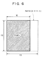
- the shape of the pixel (the hatched portion in FIG. 6) becomes about 30 % longer in the vertical direction than in the horizontal.
- printing having a correct aspect ratio cannot be obtained in some cases. That is, there is the problem that when, for example, a printer performs image formation assuming that the digital image data it receives have been sampled with an aspect ratio of 1 : 1, a correct aspect ratio is not provided in the resulting printing.
- the aspect ratio may be changed in accordance with the printer. This approach, however, necessitates a complicated operation. In addition, if it is desired to deal with a plurality of kinds of video signals, complicated setting of operation conditions is further needed.
- image processing apparatus as set out in claim 1.
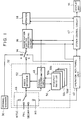
- FIG. 1 is a block diagram of the configuration of an apparatus according to the preferred embodiment of the present invention.
- an original scanner 30 an interface 32 for a plurality of kinds of video signal inputs, a selection switch 34 between the output of the original scanner 30 and the output of the interface 32, an XY magnification varying processing circuit 36, a printer 38, an operation key/panel unit 40, a system control circuit 42 comprising a microcomputer, and display unit 44.
- a selection switch 46 for a plurality of kinds of input video signals.
- a signal discrimination circuit 48 discriminates the kind of input video signal, for example, according to the frequency of the synchronizing signal or the sampling frequency of the video signal. A detailed explanation of the signal discrimination circuit 48 will be provided later.
- Look-up tables (LUTs) 50 (50a, 50b, 50c and 50d) hold information relating to the aspect ratios of respective types of video signal.
- a video decoder 52 converts an output video signal from the selection switch 46 into a signal having the same configuration as an output signal from the scanner 30 in accordance with the result of discrimination obtained by the signal discrimination circuit 48.
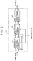
- FIG. 2 shows the configuration of the video decoder 52.
- a circuit 54 converts a composite signal into components, luminance (Y′) and color (C′).
- An RGB (red, green and blue) primary color forming circuit 56 converts the luminance and color signals Y′ and C′ into RGB signals.
- a YMC (yellow, magenta and cyan) complementary color forming circuit 58 performs YMC complementary color forming processing suitable for the printer 38 for the RGB signals.
- the circuits 54 and 56 are controlled according to the result of discrimination provided by the signal discrimination circuit 48.
- the switches 34 and 46 are switched in accordance with this setting operation. It is assumed that the switch 34 selects the output of the interface 32.
- the signal discrimination circuit 48 discriminates the kind of the input video signal from the synchronizing signal or the sampling frequency of the video signal selected by the switch 46. Without using the sampling frequency, the clock frequency of video data may be detected by a PLL circuit, or an identification signal may be received from the video signal source via another signal line.
- the signal discrimination circuit 48 refers the result of discrimination to the LUT 50, reads information of the corresponding aspect ratio from the LUT 50, and supplies the magnification varying processing circuit 36 and the system control circuit 42 with the read information.
- the video decoder 52 performs video signal processing in accordance with the result of the discrimination by the signal discrimination circuit 48, and outputs a color image signal suitable for the printer 38.
- the output of the video decoder 52 is supplied to the magnification varying processing circuit 36 via the switch 34.
- the magnification varying processing circuit 36 performs aspect ratio varying processing for the output of the video decoder 52 so that the aspect ratio of a pixel becomes 1 : 1.
- the magnification varying processing circuit 36 also performs magnification/reduction processing in accordance with the varying magnification ratio set by the operation key/panel unit 40.
- the output of the magnification varying processing cirruit 36 is supplied to the printer 38, which outputs a color print having no distortion in the horizontal and vertical directions (as compared with printing the output of the scanner 30).
- the printer 38 may be either an electrophotographic printer or an ink-jet-type printer. The essential point is that the printer has a printing function.
- a FIFO (first-in-first-out) memory 120 is provided for writing read data in a frame memory 112 and subsequently reading the data to the printer 38.
- This memory 120 is an asynchronous FIFO memory for converting (changing) the amount of data in units of a line, and may, for example, comprise a FIFO memory having a configuration of 2048 x 8 bits since the number of effective pixels of a high-definition image signal is 1920 x 1035 pixels.
- a memory controller 122 receives a horizontal synchronizing signal Hsync and a vertical synchronizing signal Vsync from the printer 38, and generates a read command signal RM for the frame memory 112, a write enable signal WE and a read enable signal RE for the memory 120, and a video enable signal VE indicating the effective image period for the printer 38 in synchronization with the signal Hsync.
- FIG. 8 i) shows a signal Hsync from the printer 38
- FIG. 8 ii) shows a read command signal for the frame memory 112
- FIGS. 8 iii) and 8 iv) show write and read enable signals for the FIFO memory 120, respectively
- FIG. 8 v) shows a video enable signal VE to be output to the printer 38.
- the memory controller 122 shown in FIG. 7 outputs to the FIFO memory 120 write clock signals WCLK at a frequency of 74.25 MHz and read clock signals RCLK at a frequency of 71.28 Mhz.
- the FIFO memory 112 shown in FIG. 7 comperisates for speed differences between the image signals of the frame memory 112 and the speed of 71.28 MHz of the printer 38.
- magnification varying processing using pixel skipping may be realized.
- Various other kinds of magnification varying processing may be considered for the present embodiment.
- a scanning frequency check circuit 1100 checks the number of vertical scanning lines of an input television signal. If the number is 1125, the circuit 1100 determines that the signal is are HDTV signal. If the number is 525, the circuit 1100 determines that the signal is an NTSC signal (for the purpose of simplifying the explanation, consideration of the PAL system used in Brasil, and the like will be omitted). If the number is 625, after checking the modulation method by a color signal demodulation circuit 1110, the circuit 1100 determines that the signal is a PAL signal in the case of AM, and that the signal is a SECAM signal in the case of FM. The circuit 1100 inputs the result of discrimination of the kind of the input television signal to the system control circuit 42.
- the system control circuit 42 controls respective units including the printer 38 in accordance with the operation of the operation key/panel unit 40, and displays the contents of setting by the system control circuit 42 on the display unit 44.
- the NTSC composite signal subjected to 4 fsc sampling selected by the switch 46 is separated into a luminosity signal and a color signal by the conversion circuit 54 of the video decoder 52, further converted into RGB signals by the RGB primary color forming circuit 56, and subjected to YMC complementary color forming processing suitable for the printer 38 by the YMC complementary color forming circuit 58.
- the output of the YMC complementary color forming circuit 58, serving as the output of the video coder 52, is supplied to the magnification varying processing circuit 36 via the switch 34.
- Information of double-size printing is supplied from the system control circuit 42 to the magnification varying processing circuit 36.
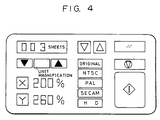
- the display device 44 displays "200 %" to indicate the magnification. In the case of unit magnification, only "unit magnification" is displayed. Data relating to the correction processing of the aspect ratio of a pixel are not displayed except when it is requested. Thus, it is possible to provide an apparatus which is easy to handle.
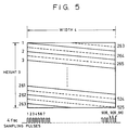
- an image signal conforming to the HD standard having the width of the BTA standard, has 2200 pixels in the horizonal direction and 1125 scanning lines in the vertical direction, and 1920 effective pixels in the horizontal direction and 1035 effective scanning lines in the vertical direction.
- the aspect ratio of a pixel is 137.4:125, as shown in FIG. 10.
- the size of the pixel in the horizontal direction may be set to a reduction ratio of 125/137.5, that is, about 90 %.
- the number of scanning lines in the vertical direction is 625, and the number of pixels in the horizontal direction becomes 851 when the image signal is sampled with a frequency three times the frequency of the color sub-carrier.
- the aspect ratio of a pixel becomes 208.3:212.75.
- the size of the pixel in the horizontal direction may be set to a magnification ratio of 212.75/208.3, that is, about 103 %.
- a signal conforming to the SECAM standard may be dealt with in the same manner as in the case of a signal conforming to the PAL standard.
- a signal conforming to one Standard is selected by the selection switch 46 in accordance with a signal from the operation key/panel unit 40, and is input to the video decoder 52.
- data of the above-described varying magnification ratio selected from the XY aspect ratio LUTs 50a - 50d in accordance with the discrimination by the signal discrimination circuit 48 are set to the magnification varying processing circuit 36. It is thereby possible to obtain an excellent image from the printer 38.
- FIG. 3 shows a display surface and an example of display using the operation key/panel unit 40 and the display unit 44 in the present embodiment.
- a display surface 60 displays the number of prints.
- a down switch 62D and an up switch 62U are used for setting the number of prints.
- a clear key 64 clears the settings.
- an excellent print image may be easily obtained without misoperation even if, for example, the user erroneously inputs a signal conforming to the PAL standard to an input terminal for a signal conforming to the NTSC standard.
Landscapes
- Engineering & Computer Science (AREA)
- Multimedia (AREA)
- Signal Processing (AREA)
- Human Computer Interaction (AREA)
- Television Signal Processing For Recording (AREA)
- Editing Of Facsimile Originals (AREA)
Claims (9)
- Appareil de traitement d'image comprenant un moyen (46) pour recevoir un signal d'image numérique; etun moyen (36) pour faire varier le rapport de pixels horizontaux-verticaux du signal d'image numérique afin de générer un second signal d'image numérique; ledit moyen de réception étant apte à recevoir une pluralité de différents signaux d'image numériques ayant différents rapports de pixels horizontaux-verticaux, et ledit appareil comprenant en outre un moyen (48) pour faire la discrimination entre les différents signaux d'image numériques afin de générer un signal de commande pour commander ledit moyen de variation, de telle sorte que le second signal d'image numérique a le même rapport de pixels horizontaux-verticaux quel que soit le rapport de pixels horizontaux-verticaux du signal d'image numérique reçu.
- Appareil selon la revendication 1, comportant un moyen de commutation (34) connecté audit moyen de variation et apte à commuter entre un signal d'entrée généré par un dispositif de balayage (30) et un signal reçu par ledit moyen de réception.
- Appareil selon la revendication 2, dans lequel ledit moyen de variation comprend un circuit pour faire varier l'amplification des signaux d'image qui lui sont appliqués et pour fournir un second signal d'image numérique sous la forme d'un signal de sortie vers une imprimante, de telle sorte que le second signal d'image numérique peut être reproduit.
- Appareil selon l'une quelconque des revendications précédentes, dans lequel les différents signaux d'image numériques sont tous conformes à des normes d'émission.
- Appareil selon l'une quelconque des revendications prédédentes, comportant une imprimante pour reproduire ledit signal d'image numérique d'enregistrement.
- Appareil selon la revendication 5, dans lequel ledit moyen de réception comporte un moyen (40) de sélection manuelle pour sélectionner l'un quelconque des signaux d'image conformes à ladite pluralité de types de normes d'émission.
- Appareil selon l'une quelconque des revendications précédentes, dans lequel ledit moyen de variation comporte une mémoire (120) pour stocker un signal d'image reçu par ledit moyen de réception, et un moyen (122) pour commander la lecture à partir de ladite mémoire de manière à effectuer la variation requise du rapport de pixels horizontaux-verticaux.
- Appareil selon l'une quelconque des revendications précédentes, dans lequel lesdits différents signaux d'image numériques sont conformes à des normes NTSC et PAL.
- Procédé de traitement d'image comprenant:la réception d'un premier signal d'image numérique capable d'avoir une pluralité de rapports de pixels horizontaux-verticaux, la discrimination du rapport de pixels horizontaux-verticaux du premier signal d'image numérique et l'utilisation du résultat de la discrimination pour faire varier le rapport de pixels horizontaux-verticaux afin de générer un second signal d'image numérique approprié pour un moyen de reproduction, et la reproduction du second signal d'image numérique.
Applications Claiming Priority (2)
| Application Number | Priority Date | Filing Date | Title |
|---|---|---|---|
| JP160368/90 | 1990-06-19 | ||
| JP16036890A JP3189010B2 (ja) | 1990-06-19 | 1990-06-19 | 画像処理装置 |
Publications (3)
| Publication Number | Publication Date |
|---|---|
| EP0462784A2 EP0462784A2 (fr) | 1991-12-27 |
| EP0462784A3 EP0462784A3 (en) | 1992-04-15 |
| EP0462784B1 true EP0462784B1 (fr) | 1996-04-10 |
Family
ID=15713467
Family Applications (1)
| Application Number | Title | Priority Date | Filing Date |
|---|---|---|---|
| EP91305479A Expired - Lifetime EP0462784B1 (fr) | 1990-06-19 | 1991-06-18 | Appareil et procédé pour le traitement d'images |
Country Status (4)
| Country | Link |
|---|---|
| US (1) | US5493418A (fr) |
| EP (1) | EP0462784B1 (fr) |
| JP (1) | JP3189010B2 (fr) |
| DE (1) | DE69118589T2 (fr) |
Families Citing this family (17)
| Publication number | Priority date | Publication date | Assignee | Title |
|---|---|---|---|---|
| JP3184263B2 (ja) * | 1991-10-11 | 2001-07-09 | 株式会社日立製作所 | ビデオプリンタ装置 |
| GB9221201D0 (en) * | 1992-10-08 | 1992-11-25 | Donohoe Vincent | Video printer |
| US5485553A (en) * | 1993-10-29 | 1996-01-16 | Hewlett-Packard Company | Method and apparatus for managing and initiating video capture and printing |
| US5943097A (en) * | 1993-12-24 | 1999-08-24 | Canon Kabushiki Kaisha | Image processing means for processing image signals of different signal formats |
| WO1995034880A1 (fr) * | 1994-06-14 | 1995-12-21 | Nanao Corporation | Systeme de reglage d'un ecran video |
| US5717469A (en) * | 1994-06-30 | 1998-02-10 | Agfa-Gevaert N.V. | Video frame grabber comprising analog video signals analysis system |
| JP3495826B2 (ja) | 1995-08-24 | 2004-02-09 | 富士写真フイルム株式会社 | ファイリング・システムおよび再生装置 |
| US6108005A (en) * | 1996-08-30 | 2000-08-22 | Space Corporation | Method for producing a synthesized stereoscopic image |
| JP3695861B2 (ja) * | 1996-10-16 | 2005-09-14 | ローム株式会社 | スキャンコンバータ |
| JP3788643B2 (ja) * | 1996-10-22 | 2006-06-21 | 富士写真フイルム株式会社 | 写真プリントシステム |
| US7301657B2 (en) * | 2001-06-09 | 2007-11-27 | Hewlett-Packard Development Company, L.P. | Printer including video decoder |
| JP3927995B2 (ja) * | 2001-12-27 | 2007-06-13 | ソニー株式会社 | 画像表示制御装置と画像表示制御方法及び撮像装置 |
| JP2007251821A (ja) * | 2006-03-17 | 2007-09-27 | Ricoh Co Ltd | 画像処理装置およびこれを用いた表示装置 |
| US7792355B2 (en) * | 2006-03-30 | 2010-09-07 | Canon Kabushiki Kaisha | Image processing apparatus, image processing method, and image capturing apparatus |
| DE102009042694A1 (de) * | 2009-09-23 | 2011-03-24 | Sms Siemag Ag | Modulare Führungseinrichtung |
| JP5610799B2 (ja) * | 2010-03-15 | 2014-10-22 | キヤノン株式会社 | 画像形成装置 |
| JP6097902B2 (ja) * | 2014-12-17 | 2017-03-22 | 大川精工株式会社 | 高性能生海苔裁断装置 |
Family Cites Families (14)
| Publication number | Priority date | Publication date | Assignee | Title |
|---|---|---|---|---|
| US4258385A (en) * | 1979-05-15 | 1981-03-24 | Combined Logic Company | Interactive video production system and method |
| US4658300A (en) * | 1983-03-08 | 1987-04-14 | Canon Kabushiki Kaisha | System and method for processing image signals |
| US4701808A (en) * | 1983-11-01 | 1987-10-20 | Canon Kabushiki Kaisha | Image processing apparatus with variable magnification and gray level processing |
| US4730215A (en) * | 1986-05-30 | 1988-03-08 | Rca Corporation | Compatible wide screen television system with variable image compression/expansion |
| EP0326339B1 (fr) * | 1988-01-29 | 1994-08-03 | Hitachi, Ltd. | Dispositif de visualisation vidéo pour des images à différents formats |
| IT1215909B (it) * | 1988-02-18 | 1990-02-22 | Rai Radiotelevisione Italiana | Procedimento di generazione e trasmissione di segnali televisivi a colori ad alta definizione compatibile con gli standardattuali e procedimento e apparecchiatura di ricezione didetti segnali. |
| US5146548A (en) * | 1988-06-24 | 1992-09-08 | Moore Business Forms, Inc. | Method and apparatus for optimizing and storing contone images for subsequent half-toning and merging with text |
| JP2613933B2 (ja) * | 1988-12-02 | 1997-05-28 | 株式会社 日立製作所 | 表示容量変換装置および表示システム |
| EP0421773B1 (fr) * | 1989-10-04 | 1997-03-19 | Canon Kabushiki Kaisha | Système de traitement d'images |
| DE69026686T2 (de) * | 1989-11-22 | 1996-10-02 | Sony Corp | Drucker für Videobilddruck |
| US5097332A (en) * | 1990-05-02 | 1992-03-17 | Faroudja Y C | Processing method for wide-aspect-ratio television signal for standards-compatible transmission and display |
| US5068728A (en) * | 1990-06-22 | 1991-11-26 | Albert Macovski | Compatible increased aspect ratio television system |
| US5193000A (en) * | 1991-08-28 | 1993-03-09 | Stereographics Corporation | Multiplexing technique for stereoscopic video system |
| GB2264417B (en) * | 1992-02-17 | 1995-12-06 | Sony Broadcast & Communication | Video standards conversion |
-
1990
- 1990-06-19 JP JP16036890A patent/JP3189010B2/ja not_active Expired - Fee Related
-
1991
- 1991-06-18 EP EP91305479A patent/EP0462784B1/fr not_active Expired - Lifetime
- 1991-06-18 DE DE69118589T patent/DE69118589T2/de not_active Expired - Fee Related
-
1995
- 1995-01-30 US US08/380,203 patent/US5493418A/en not_active Expired - Lifetime
Also Published As
| Publication number | Publication date |
|---|---|
| US5493418A (en) | 1996-02-20 |
| EP0462784A2 (fr) | 1991-12-27 |
| DE69118589D1 (de) | 1996-05-15 |
| JPH0451667A (ja) | 1992-02-20 |
| DE69118589T2 (de) | 1996-09-19 |
| EP0462784A3 (en) | 1992-04-15 |
| JP3189010B2 (ja) | 2001-07-16 |
Similar Documents
| Publication | Publication Date | Title |
|---|---|---|
| EP0462784B1 (fr) | Appareil et procédé pour le traitement d'images | |
| US4768083A (en) | Digital TV having on-screen display feature | |
| KR100244227B1 (ko) | 에이치디티브이의 디스플레이용 영상 처리장치 | |
| EP0619929B1 (fr) | Procede et appareil servant a fusionner des signaux de donnees video provenant de sources multiples, et systeme multimedia integrant un tel systeme | |
| US4568981A (en) | Font recall system and method of operation | |
| US20010017666A1 (en) | Method and apparatus for converting analog video signal to digital video signal | |
| US4780756A (en) | Apparatus for producing a hard copy of a color picture from either a field or a frame of luminance and line-sequential color difference video signals | |
| US5389974A (en) | Automatic converting device of television broadcasting mode | |
| KR100338901B1 (ko) | 텔레비젼수신기 | |
| US5953075A (en) | Video signal processing apparatus with means for magnifying and processing a picture image correspondingly to video signals | |
| EP0484981B1 (fr) | Dispositif de traitement de données d'image | |
| CN1041045C (zh) | 图形发生设备 | |
| JPH06205326A (ja) | テレビジョン受像機 | |
| JPH10214075A (ja) | 画像表示装置及び画像表示方法 | |
| US5309238A (en) | Picture superposing circuit | |
| EP1197093A1 (fr) | Procede et appareil permettant d'obtenir des affichages sur ecran pour recepteur multi-colorimetrie | |
| JP2630872B2 (ja) | テレビジョン受像機 | |
| JPH03205980A (ja) | 画像処理装置 | |
| JPH06141252A (ja) | モニタ装置 | |
| US5764868A (en) | Device for printing video signal and method thereof | |
| KR100982679B1 (ko) | 비디오 장치 | |
| KR100207622B1 (ko) | 비디오프린터의 다중입력선택장치 | |
| JPH07231406A (ja) | 字幕移動機能付き子画面表示回路 | |
| JP3491958B2 (ja) | テレビジョン受像機 | |
| JPH06141254A (ja) | モニタ装置 |
Legal Events
| Date | Code | Title | Description |
|---|---|---|---|
| PUAI | Public reference made under article 153(3) epc to a published international application that has entered the european phase |
Free format text: ORIGINAL CODE: 0009012 |
|
| AK | Designated contracting states |
Kind code of ref document: A2 Designated state(s): DE ES FR GB IT NL |
|
| PUAL | Search report despatched |
Free format text: ORIGINAL CODE: 0009013 |
|
| RHK1 | Main classification (correction) |
Ipc: H04N 1/393 |
|
| AK | Designated contracting states |
Kind code of ref document: A3 Designated state(s): DE ES FR GB IT NL |
|
| 17P | Request for examination filed |
Effective date: 19920831 |
|
| 17Q | First examination report despatched |
Effective date: 19940629 |
|
| GRAH | Despatch of communication of intention to grant a patent |
Free format text: ORIGINAL CODE: EPIDOS IGRA |
|
| GRAA | (expected) grant |
Free format text: ORIGINAL CODE: 0009210 |
|
| AK | Designated contracting states |
Kind code of ref document: B1 Designated state(s): DE ES FR GB IT NL |
|
| PG25 | Lapsed in a contracting state [announced via postgrant information from national office to epo] |
Ref country code: IT Free format text: LAPSE BECAUSE OF FAILURE TO SUBMIT A TRANSLATION OF THE DESCRIPTION OR TO PAY THE FEE WITHIN THE PRESCRIBED TIME-LIMIT;WARNING: LAPSES OF ITALIAN PATENTS WITH EFFECTIVE DATE BEFORE 2007 MAY HAVE OCCURRED AT ANY TIME BEFORE 2007. THE CORRECT EFFECTIVE DATE MAY BE DIFFERENT FROM THE ONE RECORDED. Effective date: 19960410 Ref country code: ES Free format text: THE PATENT HAS BEEN ANNULLED BY A DECISION OF A NATIONAL AUTHORITY Effective date: 19960410 |
|
| REF | Corresponds to: |
Ref document number: 69118589 Country of ref document: DE Date of ref document: 19960515 |
|
| ET | Fr: translation filed | ||
| PLBE | No opposition filed within time limit |
Free format text: ORIGINAL CODE: 0009261 |
|
| STAA | Information on the status of an ep patent application or granted ep patent |
Free format text: STATUS: NO OPPOSITION FILED WITHIN TIME LIMIT |
|
| 26N | No opposition filed | ||
| REG | Reference to a national code |
Ref country code: GB Ref legal event code: IF02 |
|
| PGFP | Annual fee paid to national office [announced via postgrant information from national office to epo] |
Ref country code: NL Payment date: 20090616 Year of fee payment: 19 |
|
| PGFP | Annual fee paid to national office [announced via postgrant information from national office to epo] |
Ref country code: GB Payment date: 20090626 Year of fee payment: 19 Ref country code: DE Payment date: 20090630 Year of fee payment: 19 |
|
| REG | Reference to a national code |
Ref country code: NL Ref legal event code: V1 Effective date: 20110101 |
|
| GBPC | Gb: european patent ceased through non-payment of renewal fee |
Effective date: 20100618 |
|
| REG | Reference to a national code |
Ref country code: FR Ref legal event code: ST Effective date: 20110228 |
|
| PG25 | Lapsed in a contracting state [announced via postgrant information from national office to epo] |
Ref country code: DE Free format text: LAPSE BECAUSE OF NON-PAYMENT OF DUE FEES Effective date: 20110101 |
|
| PG25 | Lapsed in a contracting state [announced via postgrant information from national office to epo] |
Ref country code: FR Free format text: LAPSE BECAUSE OF NON-PAYMENT OF DUE FEES Effective date: 20100630 Ref country code: NL Free format text: LAPSE BECAUSE OF NON-PAYMENT OF DUE FEES Effective date: 20110101 |
|
| PG25 | Lapsed in a contracting state [announced via postgrant information from national office to epo] |
Ref country code: GB Free format text: LAPSE BECAUSE OF NON-PAYMENT OF DUE FEES Effective date: 20100618 |
|
| PGFP | Annual fee paid to national office [announced via postgrant information from national office to epo] |
Ref country code: FR Payment date: 20090624 Year of fee payment: 19 |