EP0462991B1 - Element de couplage elastique a la flexion et procede de fabrication correspondant - Google Patents
Element de couplage elastique a la flexion et procede de fabrication correspondant Download PDFInfo
- Publication number
- EP0462991B1 EP0462991B1 EP90903822A EP90903822A EP0462991B1 EP 0462991 B1 EP0462991 B1 EP 0462991B1 EP 90903822 A EP90903822 A EP 90903822A EP 90903822 A EP90903822 A EP 90903822A EP 0462991 B1 EP0462991 B1 EP 0462991B1
- Authority
- EP
- European Patent Office
- Prior art keywords
- membrane
- radially
- disc
- connection
- discs
- Prior art date
- Legal status (The legal status is an assumption and is not a legal conclusion. Google has not performed a legal analysis and makes no representation as to the accuracy of the status listed.)
- Expired - Lifetime
Links
- 230000008878 coupling Effects 0.000 title claims abstract description 98
- 238000010168 coupling process Methods 0.000 title claims abstract description 98
- 238000005859 coupling reaction Methods 0.000 title claims abstract description 98
- 238000004519 manufacturing process Methods 0.000 title claims abstract description 15
- 238000000034 method Methods 0.000 title claims description 28
- 230000008569 process Effects 0.000 title description 4
- 239000000463 material Substances 0.000 claims abstract description 26
- 230000002093 peripheral effect Effects 0.000 claims abstract description 20
- 238000003780 insertion Methods 0.000 claims abstract description 3
- 230000037431 insertion Effects 0.000 claims abstract description 3
- 239000012528 membrane Substances 0.000 claims description 144
- 238000003466 welding Methods 0.000 claims description 39
- 238000010894 electron beam technology Methods 0.000 claims description 16
- 125000006850 spacer group Chemical group 0.000 claims description 8
- 230000007704 transition Effects 0.000 claims description 8
- 230000009467 reduction Effects 0.000 claims description 4
- 238000013016 damping Methods 0.000 claims description 3
- 239000013536 elastomeric material Substances 0.000 claims description 2
- 238000003825 pressing Methods 0.000 claims description 2
- 238000010348 incorporation Methods 0.000 claims 1
- 229920001971 elastomer Polymers 0.000 abstract description 13
- 239000000806 elastomer Substances 0.000 abstract description 13
- 238000013461 design Methods 0.000 description 25
- 241001016380 Reseda luteola Species 0.000 description 16
- 230000005540 biological transmission Effects 0.000 description 6
- 230000000694 effects Effects 0.000 description 6
- 238000010276 construction Methods 0.000 description 5
- 238000012360 testing method Methods 0.000 description 5
- 238000005452 bending Methods 0.000 description 4
- 230000008901 benefit Effects 0.000 description 4
- 230000008859 change Effects 0.000 description 4
- 238000009434 installation Methods 0.000 description 4
- 230000002349 favourable effect Effects 0.000 description 3
- 239000002184 metal Substances 0.000 description 3
- 230000001419 dependent effect Effects 0.000 description 2
- 238000009826 distribution Methods 0.000 description 2
- 238000007689 inspection Methods 0.000 description 2
- 238000004073 vulcanization Methods 0.000 description 2
- 206010041953 Staring Diseases 0.000 description 1
- 230000009471 action Effects 0.000 description 1
- 239000000853 adhesive Substances 0.000 description 1
- 230000001070 adhesive effect Effects 0.000 description 1
- 150000001875 compounds Chemical class 0.000 description 1
- 230000007547 defect Effects 0.000 description 1
- 230000001066 destructive effect Effects 0.000 description 1
- 238000006073 displacement reaction Methods 0.000 description 1
- 230000005489 elastic deformation Effects 0.000 description 1
- 238000010438 heat treatment Methods 0.000 description 1
- 238000009413 insulation Methods 0.000 description 1
- 239000007788 liquid Substances 0.000 description 1
- 238000012423 maintenance Methods 0.000 description 1
- 238000005259 measurement Methods 0.000 description 1
- 238000005457 optimization Methods 0.000 description 1
- 239000003973 paint Substances 0.000 description 1
- 239000002245 particle Substances 0.000 description 1
- 230000035515 penetration Effects 0.000 description 1
- 238000009417 prefabrication Methods 0.000 description 1
- 230000000750 progressive effect Effects 0.000 description 1
- 230000005855 radiation Effects 0.000 description 1
- 230000000717 retained effect Effects 0.000 description 1
- 239000007787 solid Substances 0.000 description 1
- 238000009987 spinning Methods 0.000 description 1
- 239000000725 suspension Substances 0.000 description 1
- 238000010998 test method Methods 0.000 description 1
- 238000012546 transfer Methods 0.000 description 1
- 238000004804 winding Methods 0.000 description 1
Images




Classifications
-
- B—PERFORMING OPERATIONS; TRANSPORTING
- B23—MACHINE TOOLS; METAL-WORKING NOT OTHERWISE PROVIDED FOR
- B23K—SOLDERING OR UNSOLDERING; WELDING; CLADDING OR PLATING BY SOLDERING OR WELDING; CUTTING BY APPLYING HEAT LOCALLY, e.g. FLAME CUTTING; WORKING BY LASER BEAM
- B23K15/00—Electron-beam welding or cutting
- B23K15/04—Electron-beam welding or cutting for welding annular seams
-
- F—MECHANICAL ENGINEERING; LIGHTING; HEATING; WEAPONS; BLASTING
- F16—ENGINEERING ELEMENTS AND UNITS; GENERAL MEASURES FOR PRODUCING AND MAINTAINING EFFECTIVE FUNCTIONING OF MACHINES OR INSTALLATIONS; THERMAL INSULATION IN GENERAL
- F16D—COUPLINGS FOR TRANSMITTING ROTATION; CLUTCHES; BRAKES
- F16D3/00—Yielding couplings, i.e. with means permitting movement between the connected parts during the drive
- F16D3/50—Yielding couplings, i.e. with means permitting movement between the connected parts during the drive with the coupling parts connected by one or more intermediate members
- F16D3/72—Yielding couplings, i.e. with means permitting movement between the connected parts during the drive with the coupling parts connected by one or more intermediate members with axially-spaced attachments to the coupling parts
Definitions
- the invention relates to a flexible coupling element consisting of two membrane disks connected to one another in their radially outer circumferential area and at least one connecting part welded to the radially inner circumference of one of these membrane disks.
- Such a coupling element is known from EP-A-211 090.
- the invention has for its object to ensure in such a coupling element that the voltage curve within the coupling element, in particular with pulling axial forces and angular deflections due to radial and angular misalignment of subsequent shafts is more favorable.
- the radially inward-facing, radially inward-facing peripheral surfaces of the connecting part and the associated diaphragm disk connect flush with one another and that the radially outer connecting zone of the diaphragm disks and the radially inner connecting zone of the connecting part and the associated diaphragm disk are radially so elastic that in the case of a membrane disc deformation by increasing the axial spacing of the membrane discs in their radially inner circumferential regions, an elastic diameter reduction ⁇ R of the radially outer connection zone and an elastic diameter increase ⁇ r of the radially inner connection connection zone can occur.
- connection parts can each have a radially outwardly directed radial flange, in particular a screw flange, at their ends which are remote from one another.
- the radial flanges have different axial distances from the associated diaphragm disk.
- this creates the possibility that the one radial flange arranged at a shorter axial distance from the associated diaphragm disk has such an axial distance from the associated diaphragm disk that when screw connections are made, screw nuts can be inserted between this radial flange and the associated diaphragm disk and that the other, arranged at a greater axial distance from the associated diaphragm radial flange has such an axial distance from the associated diaphragm that when screwing screw bolts between this radial flange and the associated diaphragm can be inserted.
- One way to trim the natural frequency of the coupling element to a desired value is that a filling compound, in particular made of elastomeric material, is installed between the two membrane disks, at least in the radially outer peripheral region of the disk space enclosed between them.
- the coupling elements according to the invention are particularly suitable for the torsionally rigid transmission of high torques at the highest speeds and fulfill a compensating function in the event of axial, radial and angular misalignment of two coupled shafts by elastic deformation.
- the invention further relates to a method for producing a flexible coupling element, which consists of two membrane disks connected to one another in their radially outer circumferential area and at least one connection part welded to the radially inner circumference of one of these membrane disks, the connection part and said membrane disk being included in the weld joint area for mutually contacting opposite radially directed centering surfaces and with for mutually contacting, oppositely axially directed contact surfaces forms in such a way that the two parts, namely the connecting part and said membrane plate can be put together in a centered and axially fixed relative position, where the contact surfaces are radial connect outwards to the centering surfaces and are accessible from the outside radially for electron beam welding, and after plugging together in the contact area ch the contact surfaces from the radially outside generates an electron beam weld or laser weld.
- connection part After welding, the radially innermost area of the connection part remains in the area of the contact or counter-contact area within the associated membrane disk.
- the connection between the membrane disk and the connecting part is based on the one hand on the welding of the contact surfaces and on the other hand on the mutual contact of the centering surfaces.
- the stress curve under bending stress is undefined, all the more so since there is no regulation with regard to the depth of the electron beam weld seam in the known method.
- the part of the connecting part located within the membrane disk represents an additional mass which does not contribute to the transmission of torque.
- the invention is therefore further based on the object of modifying the above-mentioned method in such a way that a more favorable and technically easier to manage stress curve results without reducing the torsional load capacity.
- the electron beam weld or laser weld extends radially inwards to at least the centering surfaces, and that at least the material of one or the other part lying radially inwards of the centering surfaces is subsequently removed.
- the electron beam weld or laser weld is then preferably allowed to penetrate radially inward beyond the centering surfaces into the material of the respective part. This ensures that, with a minimum of material removal, it is ensured that the weld seam is also free of voids at its radially inner end.
- the centering and contact surfaces which come together during assembly can be provided by providing the connecting part with an annular recess which is open radially outwards and axially towards the associated membrane disk and which forms the contact surface on the connecting part side and the centering surface on the connecting part side and which extends radially inwards by an annular projection which can be inserted into a bore of said membrane disk is limited, and that material is removed from the inside of the connecting part after welding via the radial height of the annular projection.
- the two membrane disks can also be welded to one another in radially outer membrane areas by means of electron beam or laser welding, approximately as described in European Patent Application 211 090.
- a preferred method of manufacture is to manufacture the membrane disks on their radially outer circumference with a material thickness which facilitates the manufacture of the membrane disks, in particular on lathes, and after welding the membrane disks, the material thickness in the radially outer region of the membrane disks in a mass which increases the softness there by removal of material , especially on a lathe. This facilitates the manufacture of the membrane disks and the welding.
- the coupling element blank obtained by welding can then be easily clamped as a whole and subjected to the material removal, which leads to its final shape and softness in bending.
- the outer diameter of the membrane disc can be reduced and any protrusion of the radially outer weld seam there with regard to balancing can be eliminated.
- transition of the respective outer peripheral surface of a membrane disk to the end face of the respective membrane disk remote from the respective other membrane disk is chamfered on at least one membrane disk. In this way, discontinuities in the stress curve during bending loads can also be avoided at this point.
- the two diaphragm disks be welded before the connection part is welded.
- the procedure is to produce a coupling element with a connection part on each of the two membrane disks, each of these connection parts consisting of an axially directed connection sleeve and a connection flange directed radially outward at the end of the connection sleeve remote from the membrane disk, in particular a screw connection flange.
- the coupling element produced according to this procedure can be used in a variety of ways, namely in the most varied shaft constructions between adjoining parts of a machine system.
- connection element produces a connection element with the smallest possible flange distance, which allows the installation of a nut on a screw bolt inserted axially towards the respective membrane disk, and that the other connection element is designed with a flange distance from the associated membrane disk, which implements the insertion of a Bolt allowed in the axial direction from the annular space between the respective flange and the respective membrane disc.
- Figure 1 shows the standard element according to the invention in the finished installed condition.
- This Kunplungselement consists of membrane discs 1, 2 and connecting parts 3, 4.
- the membrane discs 1, 2 and the connecting parts 3, 4 are connected at points 50, 51 and 52 by means of electron beam welding.
- the connecting parts 3, 4 each consist of a thin-walled sleeve 3a or 4a with an enlarged flange 3b or 4b. The torque is transmitted to the flanges 3b and 4b by means of the screws 5, 6, which establish the connection to the connecting flanges of a shaft arrangement.
- the distances A, B of the flanges 3b, 4b to the diaphragm disks 1, 2 are of different sizes and are minimized with regard to the screw and nut assembly.
- the space M required for the mother assembly of the screw 5 determines the minimum distance A and for the screw assembly of the screw 6 the space S determines the minimum distance B.
- the membrane disks 1, 2 are turned outside to the diameter D and provided with bevels 7, 8.
- connection parts 3, 4 are also turned out after the electron beam welding to the same diameter d, which is dependent on the transmissible torque, and which correspond to the inside diameter of the meningre washers 1, 2.
- the flexible disk area 1a, 2a of the membrane disks 1, 2 is formed in each case from a flat end face 1b, 2b and an end face 1c, 2c which tapers outwards.
- the end faces 1b, 2b facilitate the manufacture of the membrane disks 1, 2 by using them as support faces in the manufacture of the thin-walled areas 1a, 2a.
- Figure 2 shows the state of the standard element during manufacture.
- the reworked diameters D, d ( Figure 1) behave to the original diameters D o , d o (FIG. 2) as follows: D ⁇ D O and d> d O .
- FIG. 2a shows the radially inner area of the membrane disk 2 and the associated connection area of the connection element 4.
- connection element 4 On the connection element 4 there is an annular recess 4d which forms a contact surface 4c and a radially outward centering surface 4f.
- the ring recess 4d is defined by an annular projection 4g.
- a contact surface 2d and a radially inwardly directed centering surface 2e are attached to the membrane disc 2.
- FIG. 2 also shows the test-compatible design of the welded connections 50, 51, 52 with respect to the ultrasonic test.
- This method can be used to detect, in particular, internal welding defects, which is extremely important for such high-performance couplings. It can be seen how 100% radiation of the welding cross sections is possible both before and after the finishing on the membrane disks and connecting parts by means of conventional test heads 50a, 51a, 52a. This ensures that the coupling element can also be checked for freedom from cracks during inspections after operating times.
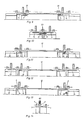
- FIG. 3 shows the design of the outer edge area of the membrane disks 1, 2 according to FIG. 1.
- the cross-section is minimized in terms of high structural strength and great radial elasticity by means of a special geometry, namely the bevels 7, 8 on both sides, the parabolic transition contours 9, 10 and the stepless transition from the centering diameter Z to the transition contour 9.
- the centering collar dimensions M and N are minimized in consideration of the electron beam welding and the centerability.
- transition contours between the end faces 1b and 2b and the cylindrical outer peripheral surfaces are provided, which serve to eliminate notch effects. These transition contours can have a parabolic shape similar to that shown at 9 and 10.
- FIG. 4 explains the effect of the radial elasticity of the radially inner and radially outer cross sections in the event of axial deformation.
- the left picture shows a section of the double membrane in the unloaded state
- the right picture shows the same section under pulling axial forces F a .
- the distance s increases by the spring travel f. Due to the resulting bulge, the stresses ⁇ r , ⁇ a , ⁇ t form in the elastic membrane surface (r means: radial, a means: axial, t means: tangential), whose directions of action are shown on a surface particle.
- the inner and outer edge areas of the double membrane are radially elastic, the inner diameters can increase by ⁇ r and the outer diameters decrease by ⁇ R, which reduces the membrane stresses ⁇ to a very high degree.
- the great effect of these measures has been demonstrated several times using tension measurements using strain gauges.
- the same effect also occurs when the membranes are subjected to deformation due to angular deflection with radial and angular misalignment of the shafts.
- the production of the final contour of the radially inner and radially outer edge regions only after welding also results in advantages when manufacturing the thin-walled surface regions 1a and 2a.
- the solid edge areas present before welding make this manufacturing process easier, in particular by better workpiece clamping, less susceptibility to warping and vibration and easier achievement of a high surface quality.
- FIG. 5 shows a shaft arrangement, formed from two coupling elements according to FIG. 1, an intermediate sleeve 12 and two hubs 13 flanged to the side of the respective parts 3.
- a separate, annular insert 14 is arranged in such a way that one end thereof reaches into the respective part 3 with radial play.
- the wavelength can be adapted to the respective installation situation via the intermediate sleeve 12.
- the double membranes enable this reduction by pressing the two membrane disks together with the aid of simple means.
- the hubs 13 can be designed differently so that all types of shaft / hub connections are possible. If it is not possible to adapt the hub flange 16 to the flange 3b of the connecting part 3, an adjustment can be carried out with the aid of an intermediate flange, the coupling elements being able to remain unchanged.
- Figure 6 shows a short design of a shaft connection according to the invention.
- the design of the coupling element according to FIG. 1 allows the shaft hub 13 to be arranged inside the respective coupling element while the shaft diameter remains the same.
- the hubs 13 arranged on the inside also fulfill the safety function of the insert 14 of FIG. 5 in the event of membrane damage.
- FIG. 7 shows a shaft half with coupling elements of the invention, which is capable of alternately transmitting external axial forces.
- the membrane discs are not loaded by these axial forces.
- the insert 14 has a flange 17 which engages in the area of an intermediate disk 18.
- the transfer of an axial force takes place, for example, from the hub 13 via the parts 4 and 14 and via the flange 17 into the intermediate sleeve 12.
- the flange 17 is arranged in an angularly movable manner with little axial play in the space formed by the intermediate disk 18. The angular mobility of the double membrane is retained even with this design.
- FIG. 8 shows a shaft connection with the same function as in FIG. 7, but in a short construction according to FIG. 6.
- Flanges 19 are fastened to the hubs 13 for the transmission of an axial force.
- Two intermediate disks 20 provide space for the flanges 19. The arrangement of the intermediate disks 20 means that the machines and coupling elements can be easily installed and removed without any axial displacement.
- FIG. 9 shows a shaft connection with coupling elements according to the invention, in which an "emergency stop" after a diaphragm rupture is provided as an additional function.
- the insert 14 has a toothing 21 which engages in a toothing of an intermediate disk 22 with increased backlash.
- the increased backlash normally prevents torque transmission through flank contact. In the event of damage, the torque is briefly transmitted via this pair of teeth.
- FIG. 10 shows a shaft connection with the same function as in FIG. 9, but in a short construction according to FIG.
- the toothed couplings 21 are arranged between the inserts 14 on the one hand and the washers 23 on the other hand, as shown and described in FIG. 9.
- FIG. 11 shows a shaft connecting half with coupling elements according to the invention, in which, in the case of long, heavy intermediate sleeves 12, the diaphragm disks are relieved of weight by means of angularly movable radial bearings 24 in the region of the center planes of the double diaphragms.
- the intermediate sleeve 12 is supported by the radial bearings 24 and flanges 25 directly on the respective shaft hub 13 in terms of weight.
- axial mobility between the inserts 14 and the radial layers 24 is provided.
- Figure 12 shows a shaft connection with coupling elements according to the invention, in which two coupling elements are arranged in tandem in a row to increase the axial elasticity.
- the coupling element attached directly to the hub 13 can be arranged in an angularly rigid manner by radial support on the hub 13 without the increase in the axial elasticity being called into question.
- Figure 13 shows a shaft connection with coupling elements according to the invention in the state during a complete balancing.
- radial threaded holes are provided in the inserts 14 or in the opposite sleeves of the connecting parts.
- FIG. 14 shows a diaphragm coupling half consisting of two diaphragm disks 1, 2 and the connecting parts 3, 4 with more details approximately corresponding to FIG. 1.
- an elastomer material is vulcanized into the interior of the double diaphragm 1, 2 to form a rubber-metal connection.
- Elastomers are able to spring, damp and insulate.
- the axial and angular rigidity of the double membrane 1, 2 can therefore also be changed subsequently by the elastomer material 60, which in turn affects the natural frequency of the coupling. It is thus possible to shift resonance speeds in such a way that the operational safety of the overall system is not endangered.
- the existing damping capacity of the elastomer material has a gentle effect on the connected units, especially in resonance areas. This increases the lifespan of the entire system.
- the size of the stiffness and damping can be varied by the degree of filling (mass of the installed elastomer material) and the Shore hardness of the elastomer material. The mass and the mass moment of the total winding is only slightly increased due to the low specific elastomer weight. The additional insulation properties also reduce structure-borne noise and thus have a noise-reducing effect.
- the vulcanization takes place during rotation and using modern binding systems. Depending on the type of elastomer material, its direct connection to the metal can be achieved or suitable adhesives are applied to the metal beforehand. The initially liquid elastomer material is distributed using the centrifugal process. The spinning must be maintained until the material is sufficiently hardened by the progressive vulcanization to maintain its distribution.
- FIG. 15 shows a tensioning device for the external weldings 50, which are advantageously to be carried out first, on a plurality of double membranes 1, 2.
- the necessary tensioning of the membranes 1, 2 takes place by means of identical, one-piece spacer rings 27, the two end disks 28, a tensioning bolt 29, a nut 30 and one Spring washer 31.
- the spring washer 31 elastically compensates for the axial shrinkage during the welding processes and thereby prevents welding errors by gaping at the welding joints.
- FIG. 16 shows a clamping device for the inner welds 51 on a plurality of coupling elements, which can each be constructed in accordance with FIG. 1.
- the parts 1, 3 and 2, 4 are clamped here using a number of identical, segment-like spacer rings 30 between respectively associated membrane disks 1, 2.
- the clamping bolt 29, the nut 30 and the spring ring 31 are used again, the Suspension between the radially inner regions of the membrane disks 1 and 2 is prevented by the segmented spacer rings 30.
- the spacer rings 30 can be easily removed after welding by slightly stretching the double membrane.
- the number of double membranes (FIG. 15) or coupling elements (FIG. 16) to be arranged simultaneously in the tensioning device depends on the dimensions of the welding machine chamber available. If there are more than two coupling elements, the two connecting parts 4 are screwed and centered by means of the screws 5 (FIG. 1).
- FIG. 17 two coupling elements 1, 2, 3, 4 and 1 ', 2', 3 ', 4' with connecting flanges 3b, 4b and 3'b, 4'b can be seen side by side.
- a hub 70 is installed in the left figure.
- a hub 70 ' is attached in the right figure. This is made possible by different inner diameters.
- the outer diameter of the membrane discs can be the same size.
- the flange diameters G are the same.
- the flange diameters G and H differ.
- the axial distances of the flanges 3b and 4b, which are labeled A and B, are again as in FIG. 1.
- the axial flange distances are C equal to each other.
- the deformability is advantageously increased by the larger flexible disk area.
- the special feature of the invention is, among other things, that comprehensive optimization is achieved by means of a simple and uniform standard coupling element. It can be used in many ways without changes will.
- the transmission systems to be won in this way meet the high technical requirements to an extent not yet achieved.
- the all-round, integral connection of the parts of the standard element by means of electron beam welding results in a high level of functional and operational reliability that cannot be achieved with the known releasable connection types when transmitting high torques at the highest speeds and deformations.
- the standard coupling element has a complete material utilization with regard to the torque transmission in the entire cross-section, which is minimized to maximum structural strength; Cross-sectional areas that do not transmit torque are not available. As a result of this consistent lightweight construction, the dimensions and wall thicknesses are extremely small and consequently also the mass and the moment of mass.
- the coupling elements according to the invention require no maintenance and permit inspections at large time intervals.
- the size of the standard coupling element and the arrangement of flanges on both sides with minimized, unequal distances to the double membrane enable the universal use of the coupling element within a series system as well as the large number of design variants.
- the standard coupling element can be used unchanged for grown shaft flanges, for shaft hubs that are arranged on the side or inside the coupling element, for shaft hubs with all types of shaft / hub connection and for intermediate shafts with different functions and dimensions.
- the insert 14 also fulfills a safety function by preventing the parts arranged between the two double membranes from becoming detached in the event of membrane damage. Due to the relatively small diameter of the inserts 14, the coupling mass is increased only slightly.
- the standardization of the standard coupling element also drastically reduces the manufacturing costs: It is possible to prefabricate the coupling element in various, torque-dependent sizes and to store it in the finished state. In prefabrication, the welding according to FIGS. 15 and 16 can be carried out on several elements simultaneously. This reduces the set-up costs as well as the costs for evacuating the welding chamber and for heat treatment after welding in the vacuum furnace, depending on the number of elements to be provided at the same time.
- the stock also considerably reduces the delivery time for such couplings, which is very important, especially in coupling construction.
- the standard coupling element allows particularly large axial and angular deformations. This important advantage is achieved through the use of the double membrane. Compared to the single diaphragm joint, the possible deformations double and the spring stiffness is reduced by half.
- the thin-walled design of the inner and outer edge area also increases the elastic membrane surface in between. This leads to even greater deformability and even lower spring stiffness.
- the standard coupling element enables the welded connection to be checked in a simple manner even after operating times using the known non-destructive test methods.
- the standard coupling element allows for a complete balancing of the assembled shaft section according to Figure 13.
- the balancing can be further improved by rigidly setting the double diaphragms during the balancing process.
- the coupling state generated by tensioning corresponds to the state of the installed coupling with zero alignment of the shafts. This measure ensures the best running precision and allows the highest speeds as a particularly important advantage of this coupling design.
- the stiffness and frequency can also be changed retrospectively using the elastomer material inside the standard coupling element. Filling the double membrane requires access from the inside. The detachable connection of the insert 14 makes this possible. Elastomers also dampen and dampen vibrations and sound.
- the design variants shown represent only a selection of the most common types.
- the standard coupling element which does not change, can be used to create a number of other designs, such as: torsionally flexible designs with torsion shaft as an intermediate sleeve; electrically insulated designs; Designs with exact length adjustment by means of adapter washers (e.g. pre-tensioned couplings); axially limited designs with resilient end positions; Designs with predetermined breaking point for torque limitation; Designs with quick torque disconnection.
Landscapes
- Engineering & Computer Science (AREA)
- Mechanical Engineering (AREA)
- General Engineering & Computer Science (AREA)
- Diaphragms And Bellows (AREA)
- Welding Or Cutting Using Electron Beams (AREA)
- Laser Beam Processing (AREA)
- Mechanical Operated Clutches (AREA)
Abstract
Claims (22)
- Elément d'accouplement élastique en flexion, composé de deux disques de membrane (1, 2) reliés entre eux dans leur secteur périphérique extérieur radialement et d'au moins une pièce de raccordement (3, 4) soudée sur la périphérie intérieure radialement de l'un de ces disques de membrane (1, 2), caractérisé en ce que des surfaces périphériques de la pièce de raccordement (3, 4) et du disque de membrane (1, 2) correspondant, situées dans le secteur périphérique intérieur radialement et orientées vers l'intérieur radialement sont raccordées l'une à l'autre de niveau et en ce que la zone de liaison extérieure radialement des disques de membrane et la zone de liaison intérieure radialement de la pièce de raccordement (3, 4) et du disque de membrane correspondant sont élastiques radialement, de telle sorte que lors d'une déformation du disque de membrane par l'accroissement de l'écart axial des disques de membrane (1, 2) dans leurs secteurs périphériques intérieurs radialement, il puisse se produire une réduction élastique ΔR du diamètre de la zone de liaison extérieure radialement et une augmentation élastique Δr du diamètre de la zone de liaison intérieure radialement.
- Elément d'accouplement élastique en flexion selon la revendication 1, caractérisé en ce que des surfaces périphériques de la pièce de raccordement (3, 4) et du disque de membrane (1, 2) correspondant, situées dans le secteur périphérique intérieur radialement et orientées vers l'extérieur radialement, se raccordent l'une à l'autre de niveau.
- Elément d'accouplement élastique en flexion selon la revendication 1 ou 2, caractérisé en ce qu'une pièce de raccordement (3a, 4a) en forme de manchon se raccorde sur chaque disque de membrane (1, 2) dans le secteur périphérique intérieur radialement, ces pièces de raccordement (3a, 4a) étant orientées à l'opposé l'une de l'autre.
- Elément d'accouplement élastique en flexion selon la revendication 3, caractérisé en ce que les pièces de raccordement (3a, 4a) présentent chacune à leurs extrémités éloignées l'une de l'autre une bride radiale (3b, 4b), en particulier une bride de vissage, orientée vers l'extérieur radialement.
- Elément d'accouplement élastique en flexion selon la revendication 4, caractérisé en ce que les brides radiales (3b, 4b) présentent par rapport au disque de membrane (1, 2) correspondant à chacune, des écarts axiaux (M, S) différents.
- Elément d'accouplement élastique en flexion selon la revendication 5, caractérisé en ce que la bride radiale (3b) disposée avec l'écart axial le plus court par rapport au disque de membrane (1) correspondant présente un écart axial (M) par rapport au disque de membrane (1) correspondant tel que, lors de l'application de vissages (5), des écrous filetés puissent être introduits entre cette bride radiale (3b) et le disque de membrane (1) correspondant, et en ce que l'autre bride radiale (4b) disposée avec l'écart axial (S) le plus grand par rapport au disque de membrane (2) correspondant présente un écart axial (S) par rapport au disque de membrane (2) correspondant tel que, lors de l'application de vissages (6), des boulons filetés (6) puissent être introduits entre cette bride radiale (4b) et le disque de membrane (2) correspondant.
- Elément d'accouplement élastique en flexion selon l'une quelconque des revendications 1 à 6, caractérisé en ce qu'une masse de remplissage (60), en particulier en matériau élastomère, est intégrée entre les deux disques de membrane (1, 2) au moins dans le secteur périphérique ' extérieur radialement de l'espace en forme de disque délimité entre eux.
- Procédé pour la fabrication d'un élément d'accouplement élastique en flexion selon l'une quelconque des revendications 1 à 7, qui se compose de deux disques de membrane (1, 2) reliés entre eux dans leur secteur périphérique extérieur radialement (D) et d'au moins une pièce de raccordement (3, 4) soudée sur la périphérie intérieure radialement de l'un de ces disques de membrane (1, 2), dans lequel la pièce de raccordement (3, 4) et ledit disque de membrane (1, 2) sont formés dans le secteur du joint soudé (51, 52) avec des surfaces de centrage (2e, 4f) orientées à l'opposé radialement et destinées à un appui mutuel, et avec des surfaces de contact (2d, 4c) orientées à l'opposé axialement et destinées à 'un appui mutuel, de telle sorte que les deux pièces (2, 4), c'est-à-dire la pièce de raccordement (4) et ledit disque de membrane (2), puissent être réunies dans une position relative centrée et fixée axialement (Figure 2a), les surfaces de contact (2d, 4c) se raccordant vers l'extérieur radialement sur les surfaces de centrage (2e, 4f) et étant accessibles de l'extérieur radialement en vue d'un soudage par bombardement électronique, et une soudure (52) par bombardement électronique ou par laser étant produite de l'extérieur après l'assemblage dans le secteur de contact des surfaces de contact (2d, 4c), caractérisé en ce que le joint de soudure par bombardement électronique ou par laser (52) s'étend radialement vers l'intérieur au moins jusqu'aux surfaces de centrage (2e, 4f), et en ce que le matériau situé au moins à l'intérieur radialement des surfaces de centrage (2e, 4f) de l'une (4) ou l'autre pièce (2) est ensuite enlevé.
- Procédé selon la revendication 1, caractérisé en ce que le joint de soudure (52) par bombardement électronique ou par laser pénètre radialement vers l'intérieur au-delà des surfaces de centrage (2e, 4f) dans le matériau de chaque pièce (2, 4).
- Procédé selon la revendication 8 ou 9, caractérisé en ce que la pièce de raccordement (4) est pourvue d'un évidement annulaire (4d) ouvert radialement vers l'extérieur et axialement vers ledit disque de membrane (2) et formant la surface de contact (4c) du côté de la pièce de raccordement et la surface de centrage (4f) du côté de la pièce de raccordement, lequel est délimité vers l'intérieur radialement par une saillie annulaire (4g) pouvant être introduite dans un trou dudit disque de membrane (2), et en ce qu'après le soudage du matériau est enlevé de la pièce de raccordement (4) à partir de l'intérieur sur la hauteur radiale de la saillie annulaire (4g).
- Procédé selon l'une quelconque des revendications 8 à 10, caractérisé en ce que les deux disques de membrane (1, 2) sont également soudés ensemble dans leurs secteurs de membrane extérieurs radialement par une soudure (50) par bombardement électronique ou par laser.
- Procédé selon l'une quelconque des revendications 8 à 11, caractérisé en ce que les disques de membrane (1, 2) sont fabriqués avec une épaisseur de matériau facilitant la fabrication des disques de membrane (1, 2) sur leur périphérie extérieure radialement (Figure 2), et l'épaisseur de matériau est réduite par enlèvement de matériau après le soudage des disques de membrane (1, 2) dans le secteur extérieur radialement des disques de membrane (1, 2), dans une mesure accroissant la souplesse en flexion à cet endroit.
- Procédé selon la revendication 12, caractérisé en ce que le diamètre extérieur (Do) des disques de membrane est réduit.
- Procédé selon l'une quelconque des revendications 12 et 13, caractérisé en ce que la transition entre la surface périphérique extérieure de chaque disque de membrane (1, 2) et la face (1b, 2b) de chaque disque de membrane (1, 2) éloignée de l'autre disque de membrane (2, 1) est biseautée en direction d'au moins un disque de membrane (1, 2).
- Procédé selon l'une quelconque des revendications 8 à 14, caractérisé en ce qu'un soudage des deux disques de membrane (1, 2) est réalisé avant le soudage avec la pièce de raccordement (3, 4).
- Procédé selon la revendication 15, caractérisé en ce que le soudage de chacun des disques de membrane (1, 2) avec la pièce de raccordement (3, 4) correspondante, en particulier le soudage des deux disques de membrane (1, 2) avec l'une des pièces de raccordement (3, 4), est réalisé en pressant chaque pièce de raccordement (3, 4) sur le disque de membrane (1, 2) correspondant, tout en appuyant les deux disques de membrane (1, 2) l'un contre l'autre sur leur périphérie intérieure à l'aide de pièces d'écartement (30), et en ce que ces pièces d'écartement (30) sont retirées après le soudage de la pièce de raccordement ou des pièces de raccordement.
- Procédé selon l'une quelconque des revendications 8 à 16, caractérisé en ce qu'après la liaison des disques de membrane (1, 2) sur leur périphérie extérieure radialement et après le raccordement d'une pièce de raccordement (3, 4) sur au moins un des disques de membrane (1, 2), un manchon de franchissement (13, 14) est intégré dans l'un des disques de membrane et/ou dans la pièce de raccordement lui correspondant, lequel franchit la fente entre les deux disques de membrane (1, 2) et fait face à la périphérie intérieure de l'autre disque de membrane et/ou à la périphérie intérieure de la pièce de raccordement correspondant à ce dernier à une certaine distance (Figures 5 et 6).
- Procédé selon l'une quelconque des revendications 8 à 17, caractérisé en ce qu'un élément d'accouplement est fabriqué avec une pièce de raccordement (3, 4) sur les deux disques de membrane (1, 2), chacune de ces pièces de raccordement (3, 4) se composant d'un manchon de raccordement (3a, 4a) orienté axialement et d'une bride de raccordement (3b, 4b), en particulier une bride de vissage, orientée vers l'extérieur radialement à l'extrémité du manchon de raccordement (3a, 4a) éloignée du disque de membrane.
- Procédé selon la revendication 18, caractérisé en ce que l'un (3) des deux éléments de raccordement (3, 4) est fabriqué avec un écart de bride (M) aussi petit que possible par rapport au disque de membrane (1) correspondant, qui permet l'introduction d'un écrou sur un boulon fileté (5) introduit axialement en direction du disque de membrane (1) correspondant, et en ce que l'autre élément de raccordement (4) est réalisé avec un écart de bride (S) par rapport au disque de membrane (2) correspondant qui permet l'introduction d'un boulon fileté (5) dans le sens axial à partir de l'espace annulaire entre la bride (4b) et le disque de membrane (2).
- Procédé selon la revendication 18 ou 19, caractérisé en ce que des éléments de raccordement avec des brides de vissage de diamètre différent sont utilisés.
- Procédé selon l'une quelconque des revendications 18 à 20, caractérisé en ce que sur la base d'un même diamètre extérieur de disque de membrane, des éléments d'accouplement de diamètre intérieur de disque de membrane différent sont fabriqués, le mode de réalisation avec le plus grand diamètre intérieur de disque de membrane étant destiné à recevoir un moyeu de raccordement (70) à l'intérieur de l'élément d'accouplement.
- Elément d'accouplement élastique en flexion avec au moins deux disques de membrane (1, 2) reliés entre eux sur leur bord extérieur radialement selon l'une quelconque des revendications 1 à 7, caractérisé en ce que l'espace compris entre les deux disques de membrane (1, 2) est rempli, au moins dans son secteur extérieur radialement, d'une masse de remplissage (60) élastique et/ou amortissante et/ou influençant la déformation, en particulier une masse d'élastomère (60).
Applications Claiming Priority (2)
| Application Number | Priority Date | Filing Date | Title |
|---|---|---|---|
| DE3907855 | 1989-03-10 | ||
| DE3907855A DE3907855A1 (de) | 1989-03-10 | 1989-03-10 | Biegeelastisches kupplungselement und verfahren zu dessen herstellung |
Publications (2)
| Publication Number | Publication Date |
|---|---|
| EP0462991A1 EP0462991A1 (fr) | 1992-01-02 |
| EP0462991B1 true EP0462991B1 (fr) | 1993-08-11 |
Family
ID=6376057
Family Applications (1)
| Application Number | Title | Priority Date | Filing Date |
|---|---|---|---|
| EP90903822A Expired - Lifetime EP0462991B1 (fr) | 1989-03-10 | 1990-03-09 | Element de couplage elastique a la flexion et procede de fabrication correspondant |
Country Status (5)
| Country | Link |
|---|---|
| US (1) | US5364309A (fr) |
| EP (1) | EP0462991B1 (fr) |
| JP (1) | JPH0819955B2 (fr) |
| DE (2) | DE3907855A1 (fr) |
| WO (1) | WO1990010801A1 (fr) |
Cited By (1)
| Publication number | Priority date | Publication date | Assignee | Title |
|---|---|---|---|---|
| EP1936233A2 (fr) | 2006-12-20 | 2008-06-25 | Voith Turbo BHS Getriebe GmbH | Unité d'engrange dotée d'un accouplement compensateur intégré |
Families Citing this family (45)
| Publication number | Priority date | Publication date | Assignee | Title |
|---|---|---|---|---|
| DE4227180C2 (de) * | 1992-08-17 | 1995-03-09 | Gkn Automotive Ag | Gleichlaufdrehgelenk |
| DE4304611C2 (de) * | 1993-02-16 | 1994-11-24 | Kirschey Centa Antriebe | Wellenkupplung |
| DE4333517A1 (de) * | 1993-10-01 | 1995-04-06 | Buderus Guss Gmbh | Bremsscheibe für Scheibenbremsen |
| US5899813A (en) * | 1996-06-21 | 1999-05-04 | Lucas Aerospace Power Transmission | Non-welded joint using a polygon |
| US5903116A (en) * | 1997-09-08 | 1999-05-11 | Capstone Turbine Corporation | Turbogenerator/motor controller |
| US6487096B1 (en) | 1997-09-08 | 2002-11-26 | Capstone Turbine Corporation | Power controller |
| US6784565B2 (en) | 1997-09-08 | 2004-08-31 | Capstone Turbine Corporation | Turbogenerator with electrical brake |
| US5964663A (en) * | 1997-09-19 | 1999-10-12 | Capstone Turbine Corp. | Double diaphragm compound shaft |
| US6870279B2 (en) | 1998-01-05 | 2005-03-22 | Capstone Turbine Corporation | Method and system for control of turbogenerator power and temperature |
| US20020166324A1 (en) | 1998-04-02 | 2002-11-14 | Capstone Turbine Corporation | Integrated turbine power generation system having low pressure supplemental catalytic reactor |
| AT406183B (de) * | 1998-04-28 | 2000-03-27 | Ellergon Antriebstech Gmbh | Kupplungskombination aus einer ausgleichskupplung und einer drehelastischen kupplung |
| US6612112B2 (en) | 1998-12-08 | 2003-09-02 | Capstone Turbine Corporation | Transient turbine exhaust temperature control for a turbogenerator |
| DE19912797C2 (de) * | 1999-03-10 | 2001-06-07 | Mannesmann Ag | Elastische Wellenkupplung |
| JP2000337394A (ja) * | 1999-05-24 | 2000-12-05 | Ishikawajima Harima Heavy Ind Co Ltd | 高速たわみ軸継手のバランス修正方法 |
| US20030157987A1 (en) * | 2000-10-26 | 2003-08-21 | Kop Flex, Inc. | Shaft couplings with bonded flexible elements |
| DE19955051A1 (de) * | 1999-11-15 | 2001-06-21 | Hackforth Gmbh & Co Kg | Elastische Wellenkupplung |
| DE10005796B4 (de) * | 2000-02-10 | 2011-02-17 | Bhs-Sonthofen Gmbh | Drehfilteranlage |
| US6787933B2 (en) | 2001-01-10 | 2004-09-07 | Capstone Turbine Corporation | Power generation system having transient ride-through/load-leveling capabilities |
| DE10153080C1 (de) * | 2001-10-30 | 2003-06-12 | Siemens Ag | Membrankupplung |
| DE102004028266A1 (de) * | 2004-06-11 | 2005-12-29 | Linnig Antriebstechnik Gmbh | Elektromagnetisch betätigbare Reibscheibenkupplung |
| US20060079335A1 (en) * | 2004-10-11 | 2006-04-13 | Wieslaw Muskus | Method and apparatus for coupling components |
| DE102005014985A1 (de) * | 2005-04-01 | 2006-10-05 | Bhs Getriebe Gmbh | Membrankupplung mit integrierter Drehelastizität |
| DE102006042301B4 (de) * | 2006-09-08 | 2018-02-22 | Ellergon Antriebstechnik Gmbh | Membranausgleichskupplung und Lochlaibungsverbindung |
| US7824270B2 (en) | 2007-01-23 | 2010-11-02 | C-Flex Bearing Co., Inc. | Flexible coupling |
| GB2446863A (en) * | 2007-02-21 | 2008-08-27 | Smiths Aerospace Ltd | Diaphragm coupling with stops to limit range of movement |
| PT1965091E (pt) * | 2007-02-27 | 2009-09-04 | Agusta Spa | Junta de transmissão |
| DE102008008352A1 (de) * | 2008-02-08 | 2009-08-13 | J. Eberspächer GmbH & Co. KG | Bauteilverbindung |
| US8147194B2 (en) * | 2008-11-06 | 2012-04-03 | Honeywell International Inc. | Turbine engine components |
| US8162762B2 (en) * | 2009-07-01 | 2012-04-24 | Hamilton Sundstrand Corporation | Generator flexible drive coupling |
| FR2965319B1 (fr) * | 2010-09-27 | 2013-03-01 | Eurocopter France | Moyen d'accouplement flexible |
| CN102221050B (zh) * | 2011-06-24 | 2014-09-10 | 中国航空动力机械研究所 | 膜盘联轴节 |
| US8591345B2 (en) * | 2011-09-09 | 2013-11-26 | Goodrich Corporation | Flexible diaphragm coupling for axial force loading |
| FR2990011B1 (fr) | 2012-04-27 | 2014-05-02 | Eurocopter France | Moyen d'accouplement flexible, et transmission mecanique |
| US9599167B2 (en) * | 2014-09-18 | 2017-03-21 | Outotec (Finland) Oy | Method for dissipating heat in drive system for an apparatus separating hot particles |
| KR101618097B1 (ko) * | 2014-12-30 | 2016-05-09 | 아이원스 주식회사 | 동력 전달축 |
| GB2537613B (en) * | 2015-04-20 | 2019-05-22 | Rolls Royce Plc | A shaft assembly comprising a frangible coupling and a flexible coupling |
| US10480585B2 (en) | 2016-10-27 | 2019-11-19 | Goodrich Corporation | Redundant coupling arrangements |
| US10253822B2 (en) | 2016-11-03 | 2019-04-09 | Goodrich Corporation | Flexible couplings with angular limiters |
| JP7288670B2 (ja) * | 2017-03-10 | 2023-06-08 | ユニヴァーシティ オブ ワシントン | 医療用インプラントの安定性を測定および評価するための方法およびシステム |
| FR3078750B1 (fr) * | 2018-03-09 | 2020-04-03 | Safran Aircraft Engines | Accouplement flexible comprenant des soufflets et des dents de reprise de couple |
| ES2906523B2 (es) * | 2020-10-14 | 2022-09-08 | Tejasa Tc S L L | Acoplamiento elastico |
| US20240101265A1 (en) * | 2022-09-19 | 2024-03-28 | Goodrich Corporation | Flexible metallic drive shaft diaphragm having enhanced damage tolerance |
| CN116604255A (zh) * | 2023-05-19 | 2023-08-18 | 中国航发控制系统研究所 | 带支承结构的膜盘组件焊接工装 |
| WO2025075548A1 (fr) * | 2023-10-02 | 2025-04-10 | Stin Global Pte. Ltd. | Appareil d'accouplement d'arbre flexible pour transmission de couple |
| CN119368978B (zh) * | 2024-11-11 | 2025-11-25 | 中国航发控制系统研究所 | 适用于开口膜盘组件的焊接工装 |
Family Cites Families (10)
| Publication number | Priority date | Publication date | Assignee | Title |
|---|---|---|---|---|
| US3124942A (en) * | 1964-03-17 | Flexible coupling | ||
| GB1091121A (en) * | 1964-02-13 | 1967-11-15 | Bendix Corp | A flexible drive-shaft coupling |
| US3543537A (en) * | 1968-11-20 | 1970-12-01 | Bendix Corp | Synchronizing coupling |
| GB1443217A (en) * | 1973-11-08 | 1976-07-21 | Mcnamee A | Flexible coupling |
| US4133188A (en) * | 1977-07-13 | 1979-01-09 | General Motors Corporation | Back-up torque transmitting structure |
| US4191030A (en) * | 1978-08-21 | 1980-03-04 | Koppers Company, Inc. | Diaphragm coupling |
| US4276758A (en) * | 1979-09-27 | 1981-07-07 | The Bendix Corporation | Fail safe redundant drive shaft apparatus including electrically operative failure detection means |
| US4560364A (en) * | 1981-11-09 | 1985-12-24 | Hughes Helicopters, Inc. | Fail-safe improvement for a flexible shaft coupling |
| DE8337492U1 (de) * | 1983-12-28 | 1985-09-26 | BHS-Bayerische Berg-, Hütten- und Salzwerke AG, 8000 München | Membrankupplung |
| DE3572526D1 (en) * | 1985-07-26 | 1989-09-28 | Bhs Bayerische Berg | Manufacturing process for a flexible coupling means for the transmission of torque |
-
1989
- 1989-03-10 DE DE3907855A patent/DE3907855A1/de not_active Ceased
-
1990
- 1990-03-09 JP JP2504202A patent/JPH0819955B2/ja not_active Expired - Fee Related
- 1990-03-09 WO PCT/EP1990/000386 patent/WO1990010801A1/fr not_active Ceased
- 1990-03-09 EP EP90903822A patent/EP0462991B1/fr not_active Expired - Lifetime
- 1990-03-09 DE DE9090903822T patent/DE59002338D1/de not_active Expired - Fee Related
- 1990-03-09 US US07/761,972 patent/US5364309A/en not_active Expired - Lifetime
Cited By (2)
| Publication number | Priority date | Publication date | Assignee | Title |
|---|---|---|---|---|
| EP1936233A2 (fr) | 2006-12-20 | 2008-06-25 | Voith Turbo BHS Getriebe GmbH | Unité d'engrange dotée d'un accouplement compensateur intégré |
| DE102006060389A1 (de) * | 2006-12-20 | 2008-06-26 | Voith Turbo Bhs Getriebe Gmbh | Getriebeeinheit mit integrierter Ausgleichskupplung |
Also Published As
| Publication number | Publication date |
|---|---|
| WO1990010801A1 (fr) | 1990-09-20 |
| JPH0819955B2 (ja) | 1996-03-04 |
| DE59002338D1 (de) | 1993-09-16 |
| JPH04501908A (ja) | 1992-04-02 |
| US5364309A (en) | 1994-11-15 |
| EP0462991A1 (fr) | 1992-01-02 |
| DE3907855A1 (de) | 1990-09-13 |
Similar Documents
| Publication | Publication Date | Title |
|---|---|---|
| EP0462991B1 (fr) | Element de couplage elastique a la flexion et procede de fabrication correspondant | |
| DE3443485C2 (fr) | ||
| DE102013018261B4 (de) | Flexible Wellenkupplung und Verfahren zur Herstellung derselben | |
| DE2645600C3 (de) | Drehsteife und Wellenverlagerungen zulassende bewegliche Kupplung | |
| DE19843632B4 (de) | Gleichlaufgelenk | |
| DE3446495A1 (de) | Kreuzgelenk fuer eine gelenkwelle | |
| EP3105461B1 (fr) | Élément de machine | |
| DE2653007A1 (de) | Vorrichtung zur verbindung einer antreibenden mit einer angetriebenen welle | |
| DE102013222753A1 (de) | Doppel-Torsionskupplung für ein Schienenfahrzeug und Verfahren zur Montage einer Doppel-Torsionskupplung | |
| AT520744B1 (de) | Elastische Kupplungsvorrichtung zur Verbindung von zwei Antriebswellen | |
| EP2242938A1 (fr) | Raccord élastique en rotation et procédé de fabrication de celui-ci | |
| DE3314322A1 (de) | Kreuzgelenk fuer eine gelenkwelle | |
| EP4143453B1 (fr) | Accouplement double extensible pour le raccordement de deux arbres avec compensation de décalage | |
| EP1001182B1 (fr) | Ensemble de joint universel pour un arbre articulé | |
| DE102016013493A1 (de) | Antriebswellenbaugruppe und Verfahren für ihre Herstellung | |
| DE2801617C3 (de) | Lagerzentrierung von geteilten Pleuelstangen | |
| EP1360425B1 (fr) | Entraineur a bride | |
| EP1588069B1 (fr) | Croisillon et dispositif a joint a croisillon | |
| WO2002066848A1 (fr) | Entraineur a bride | |
| DE102024108088B3 (de) | Ausrichthilfe, Kupplungssatz, Verfahren sowie Verwendung | |
| EP4411164B1 (fr) | Ensembles amortisseurs pour transmissions et générateurs | |
| AT525807B1 (de) | Schalldämpfungsvorrichtung für Fahrzeugräder | |
| DE3038506A1 (de) | Elastische wellenkupplung | |
| DE2741652A1 (de) | Hochbelastbare drehsteif-beugeelastische membrankupplung | |
| WO2003054403A1 (fr) | Accouplement d'arbre elastique a elements de fixation axiaux |
Legal Events
| Date | Code | Title | Description |
|---|---|---|---|
| PUAI | Public reference made under article 153(3) epc to a published international application that has entered the european phase |
Free format text: ORIGINAL CODE: 0009012 |
|
| 17P | Request for examination filed |
Effective date: 19910905 |
|
| AK | Designated contracting states |
Kind code of ref document: A1 Designated state(s): CH DE FR GB IT LI NL SE |
|
| 17Q | First examination report despatched |
Effective date: 19920922 |
|
| GRAA | (expected) grant |
Free format text: ORIGINAL CODE: 0009210 |
|
| AK | Designated contracting states |
Kind code of ref document: B1 Designated state(s): CH DE FR GB IT LI NL SE |
|
| PG25 | Lapsed in a contracting state [announced via postgrant information from national office to epo] |
Ref country code: SE Effective date: 19930811 Ref country code: NL Effective date: 19930811 |
|
| REF | Corresponds to: |
Ref document number: 59002338 Country of ref document: DE Date of ref document: 19930916 |
|
| ITF | It: translation for a ep patent filed | ||
| GBT | Gb: translation of ep patent filed (gb section 77(6)(a)/1977) |
Effective date: 19930826 |
|
| ET | Fr: translation filed | ||
| NLV1 | Nl: lapsed or annulled due to failure to fulfill the requirements of art. 29p and 29m of the patents act | ||
| PLBI | Opposition filed |
Free format text: ORIGINAL CODE: 0009260 |
|
| 26 | Opposition filed |
Opponent name: RENK TACKE GMBH Effective date: 19940413 |
|
| RAP2 | Party data changed (patent owner data changed or rights of a patent transferred) |
Owner name: BHS-CINCINNATI GETRIEBETECHNIK GMBH |
|
| PLBO | Opposition rejected |
Free format text: ORIGINAL CODE: EPIDOS REJO |
|
| APAC | Appeal dossier modified |
Free format text: ORIGINAL CODE: EPIDOS NOAPO |
|
| APAE | Appeal reference modified |
Free format text: ORIGINAL CODE: EPIDOS REFNO |
|
| PLAB | Opposition data, opponent's data or that of the opponent's representative modified |
Free format text: ORIGINAL CODE: 0009299OPPO |
|
| R26 | Opposition filed (corrected) |
Opponent name: RENK AKTIENGESELLSCHAFT Effective date: 19940413 |
|
| PLBQ | Unpublished change to opponent data |
Free format text: ORIGINAL CODE: EPIDOS OPPO |
|
| PLAB | Opposition data, opponent's data or that of the opponent's representative modified |
Free format text: ORIGINAL CODE: 0009299OPPO |
|
| R26 | Opposition filed (corrected) |
Opponent name: RENK AKTIENGESELLSCHAFT Effective date: 19940413 |
|
| REG | Reference to a national code |
Ref country code: CH Ref legal event code: PUE Owner name: BHS - BAYERISCHE BERG-, HUETTEN- UND SALZWERKE AKT |
|
| APAC | Appeal dossier modified |
Free format text: ORIGINAL CODE: EPIDOS NOAPO |
|
| PLBN | Opposition rejected |
Free format text: ORIGINAL CODE: 0009273 |
|
| STAA | Information on the status of an ep patent application or granted ep patent |
Free format text: STATUS: OPPOSITION REJECTED |
|
| 27O | Opposition rejected |
Effective date: 19990810 |
|
| REG | Reference to a national code |
Ref country code: GB Ref legal event code: IF02 |
|
| APAH | Appeal reference modified |
Free format text: ORIGINAL CODE: EPIDOSCREFNO |
|
| PGFP | Annual fee paid to national office [announced via postgrant information from national office to epo] |
Ref country code: IT Payment date: 20060331 Year of fee payment: 17 |
|
| REG | Reference to a national code |
Ref country code: CH Ref legal event code: PFA Owner name: BHS-CINCINNATI GETRIEBSTECHNIK GMBH Free format text: BHS-CINCINNATI GETRIEBSTECHNIK GMBH#HANS-BOECKLER-STRASSE 7#87527 SONTHOFEN (DE) -TRANSFER TO- BHS-CINCINNATI GETRIEBSTECHNIK GMBH#HANS-BOECKLER-STRASSE 7#87527 SONTHOFEN (DE) |
|
| PGFP | Annual fee paid to national office [announced via postgrant information from national office to epo] |
Ref country code: CH Payment date: 20080314 Year of fee payment: 19 |
|
| PGFP | Annual fee paid to national office [announced via postgrant information from national office to epo] |
Ref country code: GB Payment date: 20080320 Year of fee payment: 19 |
|
| PGFP | Annual fee paid to national office [announced via postgrant information from national office to epo] |
Ref country code: DE Payment date: 20080115 Year of fee payment: 19 Ref country code: FR Payment date: 20080314 Year of fee payment: 19 |
|
| PG25 | Lapsed in a contracting state [announced via postgrant information from national office to epo] |
Ref country code: IT Free format text: LAPSE BECAUSE OF NON-PAYMENT OF DUE FEES Effective date: 20070309 |
|
| REG | Reference to a national code |
Ref country code: CH Ref legal event code: PL |
|
| GBPC | Gb: european patent ceased through non-payment of renewal fee |
Effective date: 20090309 |
|
| REG | Reference to a national code |
Ref country code: FR Ref legal event code: ST Effective date: 20091130 |
|
| PG25 | Lapsed in a contracting state [announced via postgrant information from national office to epo] |
Ref country code: LI Free format text: LAPSE BECAUSE OF NON-PAYMENT OF DUE FEES Effective date: 20090331 Ref country code: DE Free format text: LAPSE BECAUSE OF NON-PAYMENT OF DUE FEES Effective date: 20091001 Ref country code: CH Free format text: LAPSE BECAUSE OF NON-PAYMENT OF DUE FEES Effective date: 20090331 |
|
| PG25 | Lapsed in a contracting state [announced via postgrant information from national office to epo] |
Ref country code: GB Free format text: LAPSE BECAUSE OF NON-PAYMENT OF DUE FEES Effective date: 20090309 Ref country code: FR Free format text: LAPSE BECAUSE OF NON-PAYMENT OF DUE FEES Effective date: 20091123 |