EP0463018B1 - Dichtungen - Google Patents
Dichtungen Download PDFInfo
- Publication number
- EP0463018B1 EP0463018B1 EP90904358A EP90904358A EP0463018B1 EP 0463018 B1 EP0463018 B1 EP 0463018B1 EP 90904358 A EP90904358 A EP 90904358A EP 90904358 A EP90904358 A EP 90904358A EP 0463018 B1 EP0463018 B1 EP 0463018B1
- Authority
- EP
- European Patent Office
- Prior art keywords
- sealing
- elastomer
- space
- set forth
- elastomer layer
- Prior art date
- Legal status (The legal status is an assumption and is not a legal conclusion. Google has not performed a legal analysis and makes no representation as to the accuracy of the status listed.)
- Expired - Lifetime
Links
- 238000007789 sealing Methods 0.000 title claims abstract description 134
- 229920001971 elastomer Polymers 0.000 claims abstract description 77
- 239000000806 elastomer Substances 0.000 claims abstract description 77
- 238000011065 in-situ storage Methods 0.000 claims abstract description 7
- 238000006073 displacement reaction Methods 0.000 claims abstract description 6
- 229920001296 polysiloxane Polymers 0.000 claims abstract 2
- 229920002635 polyurethane Polymers 0.000 claims abstract 2
- 239000004814 polyurethane Substances 0.000 claims abstract 2
- 239000012530 fluid Substances 0.000 claims description 18
- 238000005266 casting Methods 0.000 claims description 8
- 230000008878 coupling Effects 0.000 claims description 7
- 238000010168 coupling process Methods 0.000 claims description 7
- 238000005859 coupling reaction Methods 0.000 claims description 7
- 230000000694 effects Effects 0.000 claims description 5
- 239000012528 membrane Substances 0.000 claims description 5
- 239000002184 metal Substances 0.000 claims description 4
- 229910052751 metal Inorganic materials 0.000 claims description 4
- 238000000034 method Methods 0.000 claims 1
- 239000003566 sealing material Substances 0.000 claims 1
- 239000010720 hydraulic oil Substances 0.000 description 8
- 239000011324 bead Substances 0.000 description 6
- 239000000463 material Substances 0.000 description 6
- CKQVRZJOMJRTOY-UHFFFAOYSA-N octadecanoic acid;propane-1,2,3-triol Chemical compound OCC(O)CO.CCCCCCCCCCCCCCCCCC(O)=O CKQVRZJOMJRTOY-UHFFFAOYSA-N 0.000 description 3
- 238000012856 packing Methods 0.000 description 3
- 239000004809 Teflon Substances 0.000 description 2
- 229920006362 Teflon® Polymers 0.000 description 2
- 239000007789 gas Substances 0.000 description 2
- 125000006850 spacer group Chemical group 0.000 description 2
- RYGMFSIKBFXOCR-UHFFFAOYSA-N Copper Chemical compound [Cu] RYGMFSIKBFXOCR-UHFFFAOYSA-N 0.000 description 1
- 230000003321 amplification Effects 0.000 description 1
- 239000011230 binding agent Substances 0.000 description 1
- 230000000903 blocking effect Effects 0.000 description 1
- 229910052802 copper Inorganic materials 0.000 description 1
- 239000010949 copper Substances 0.000 description 1
- 238000010438 heat treatment Methods 0.000 description 1
- 238000009434 installation Methods 0.000 description 1
- 239000000314 lubricant Substances 0.000 description 1
- 239000000203 mixture Substances 0.000 description 1
- 238000000465 moulding Methods 0.000 description 1
- 238000003199 nucleic acid amplification method Methods 0.000 description 1
- 239000003921 oil Substances 0.000 description 1
- 230000000717 retained effect Effects 0.000 description 1
- 239000000126 substance Substances 0.000 description 1
- 238000009827 uniform distribution Methods 0.000 description 1
- 238000009834 vaporization Methods 0.000 description 1
Images


Classifications
-
- F—MECHANICAL ENGINEERING; LIGHTING; HEATING; WEAPONS; BLASTING
- F16—ENGINEERING ELEMENTS AND UNITS; GENERAL MEASURES FOR PRODUCING AND MAINTAINING EFFECTIVE FUNCTIONING OF MACHINES OR INSTALLATIONS; THERMAL INSULATION IN GENERAL
- F16J—PISTONS; CYLINDERS; SEALINGS
- F16J15/00—Sealings
- F16J15/46—Sealings with packing ring expanded or pressed into place by fluid pressure, e.g. inflatable packings
-
- F—MECHANICAL ENGINEERING; LIGHTING; HEATING; WEAPONS; BLASTING
- F16—ENGINEERING ELEMENTS AND UNITS; GENERAL MEASURES FOR PRODUCING AND MAINTAINING EFFECTIVE FUNCTIONING OF MACHINES OR INSTALLATIONS; THERMAL INSULATION IN GENERAL
- F16K—VALVES; TAPS; COCKS; ACTUATING-FLOATS; DEVICES FOR VENTING OR AERATING
- F16K1/00—Lift valves or globe valves, i.e. cut-off apparatus with closure members having at least a component of their opening and closing motion perpendicular to the closing faces
- F16K1/16—Lift valves or globe valves, i.e. cut-off apparatus with closure members having at least a component of their opening and closing motion perpendicular to the closing faces with pivoted closure-members
- F16K1/18—Lift valves or globe valves, i.e. cut-off apparatus with closure members having at least a component of their opening and closing motion perpendicular to the closing faces with pivoted closure-members with pivoted discs or flaps
- F16K1/22—Lift valves or globe valves, i.e. cut-off apparatus with closure members having at least a component of their opening and closing motion perpendicular to the closing faces with pivoted closure-members with pivoted discs or flaps with axis of rotation crossing the valve member, e.g. butterfly valves
- F16K1/226—Shaping or arrangements of the sealing
- F16K1/228—Movable sealing bodies
Definitions
- the present invention relates to a sealing as set forth in the preamble of claim 1 for packing a gap between two surfaces.
- a sealing according to the pramble of claim 1 is disclosed in DE-A-2 931 779.
- This sealing comprises an annular sealing having conical sealing surfaces.
- To prevent the annular sealing from migrating in the gap between the parts to be sealed the sealing is provided with a reduced diameter section resulting in an annular gap in the sealing space.
- An object of the invention is to provide an activable sealing, particularly a hydraulic-oil or compressed-air or mechanically operated sealing, said sealing being capable of withstanding substantial pressures, even pressures of several hundred bars, but being well suitable also for minor pressures.
- compressed air refers not only to normal air but to all gases or gas mixtures.
- a sealing of the invention finds a plurality of applications e.g. in mechanical components having considerable pressure differences on different sides of a point to be sealed, e.g. flap and ball valves, pistons etc. This type of sealing can also be used e.g. for packing the joints of underwater tunnel elements and for sealing of various door and window structures, particularly in objects intended for marine conditions and in corresponding structures.
- a sealing of the invention is characterized by what is set forth in the characterizing clause of claim 1.
- elastomer does not adhere to wall surfaces, thus allowing the displacement of elastomer in an elastomer space and/or passages in a pressurized state to a reasonable extent.
- the behaviour of elastomer resembles that of a fluid in the sense that it is incompressible, the difference from a fluid being, however, that elastomer is self-restoring after depressurization.
- the preliminary tests have indicated that at a pressure of over 200 bars, e.g. in a passage having a diameter of circa 5 mm and a length of circa 500 mm, there occurs a nearly complete equalization of pressure throughout the entire passage.
- elastomer passages/spaces must generally be worked to be larger than corresponding fluid passages.
- the elastomer can nevertheless be bonded e.g. to a sealing layer of some harder material or, when using e.g. mechanical pistons, to the head of a piston by the application of an appropriate binder, such as e.g. Chemosil X 5201, available from e.g. Henkel AG (FRG).
- an appropriate binder such as e.g. Chemosil X 5201, available from e.g. Henkel AG (FRG).
- the most significant advantage gained by a sealing of the invention is that the installation work will be facilitated as the sealing can be cast or molded to position in an already assembled device, thus avoiding damages to the sealing.
- the sealing can be pressurized/adjusted to a desired pressure reading.
- Another advantage gained by a sealing of the invention is a considerable pressure resistance and, depending on selected materials, also a considerable heat resistance.
- Another advantage is that a system provided by the sealing and its pressurizing medium can be designed as a closed system, whereby e.g. possible spills of hydraulic oil can be reliably prevented.
- Fig. 1 illustrates the sealing of e.g. a rotatable shaft 1 against a body or jacket portion 2.
- an elastomer layer 3a is fitted in a sealing space 3 whose edges are provided with inwardly directed protrusions 4. These protrusions 4 build therebetween a section A which is substantially narrower than the rest of the sealing space.
- the elastomer layer is directly moulded in situ on either side of the narrower section A, thus producing a massive sealing layer.
- Between the inner surface of sealing layer 3a and the bottom of sealing space 3 is provided a space 6a for hydraulic fluid 6 or compressed air or elastomer medium.
- a sealing means 5a On top of sealing layer 3a is preferably mounted a sealing means 5a, made of e.g.
- Sealing means 5a is preferably vulcanized to be integral with sealing layer 3a. Operation of the sealing e.g. by means of a hydraulic fluid proceeds in a manner that hydraulic fluid 6 is pressurized by using a pressurizing unit 20, described later and shown in fig. 5, whereby the hydraulic fluid applies pressure to sealing layer 3a resulting in a displacement of the sealing layer outwards and, through the action of narrow section A, a deformation in sealing 3a as well as the orientation of forces created in sealing 3a substantially against protrusions 4. This deformation of sealing 3a together with the orientation of forces against protrusions 4 prevents the removal of sealing 3a from the sealing space under pressure.
- sealing layer 3a produces a pressure effect on the harder sealing means 5a urging it against body portion 2 so as to seal or pack a gap 5 between body portion and shaft portion.
- said sealing 3a resumes its shape through the action of a return force produced by the effect of narrow section A.
- the embodiment of fig. 2 shows an example of the packing of a joint between two concrete elements 7, 8.
- a sealing 9 there is built a space 10 for a pressure medium.
- This space is formed e.g. in a manner that around a non-reinforced two-component elastomer tube is directly cast in situ a sealing 9 or a prefabricated sealing 9 is provided in a hole extending therethrough with a non-reinforced two-component elastomer tube.
- Sealing 9 is placed or moulded in the seal ing spaces made in both surfaces to be sealed.
- the sealing can be made pressure resistant by supplying said space 10 with a pressurized hydraulic fluid or compressed air or some elastomer medium, whereby the pressuriztion of hydraulic fluid can be effected e.g. by means of a pressurizing unit 20 shown in fig. 5.
- a sealing space 14 is preferably designed a dovetail groove in the edge of a door to extend around the entire periphery of a door.
- the sealing space 14 is fitted with a sealing layer 14a by casting it directly in situ around a non-reinforced two-component elastomer tube 13, preferably near the bottom of sealing space 14, whereby the pressurization of said tube 13 with the application of a hydraulic fluid can be effected by means of a pressurizing unit shown in fig. 5.
- pressurized hydraulic fluid is supplied therein, said tube 13 expands resulting in a deformation in elastomer layer 14a which, upon its outward expansion/displacement, seals a gap 12 between door 15 and jamb 16.
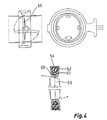
- FIG. 4 illustrates the use of a sealing of the invention in a flap valve.
- a flap 55 is normally sealed e.g. by means of a metal gasket 51 having a U-shaped cross-section.
- the performance of this gasket can be improved in accordance with the invention by casting an elastomer layer 52 in the groove of metal gasket 51.
- the casting is preferably effected on top of an elastomer tube 53 fitted in the groove, said tube being connected with pressurization means for pressurizing the tube with an appropriate medium, such as hydraulic oil, compressed air or elastomer.
- On top of elastomer layer 53 is preferably laid a sealing layer 54 which is made e.g. of harder elastomer.
- This solution can also be effected e.g. in a manner that an elastomer tube 53 fitted in the groove of a metal gasket matches in its cross-section substantially the size of said groove, the elastomer being only cast inside said tube while the tube serves as
- the pressurization of sealings of the invention is preferably effected by means of a pressurizing unit 20 shown in fig. 5.
- the pressurizing unit 20 preferably comprises a bushing-like body portion 36, fitted with a bottom section 40 for building a cavity 26 inside said body portion 36.
- the bottom section 40 is provided with a protrusion 39, fitted with an externally threading and extending outward of cavity 26.
- Protrusion 39 is provided with a hole extending into cavity 26 and preferably fitted with an internal flange 41 at the end of protrusion 39 away from cavity 26.
- the cavity 26 of body portion 36 includes a space 28 for hydraulic fluid 7 e.g. by means of an elastomeric membrane 21 and a massive elastomer layer 22.
- the bottom of cavity 26 is provided with a coupling 27, comprising a connector tube 30 which has an internal hole and one end of which is provided with an expansion 31 and the other end with a threaded portion 32.
- the coupling further includes a separate "bead” portion 33 and a separate sleeve portion 34.
- the coupling 27 is assembled in a manner that the bottom of membrane 21 carries a tubing section 35 which is pushed on top of the connector tube expansion 31 to extend beyond said expansion in the longitudinal direction. This is followed by placing said bead portion 33 on top of connector tube 30 from the end facing said threaded portion 32 and pushing it on top of tubing section 35 into the abutment with expansion 31.
- the bead portion 33 is preferably designed to include internal cones at both ends thereof. This is followed by placing said sleeve portion 34 on top of connector tube 30 from the threaded end 32 and pushing it against bead portion 33 in a manner that said tubing section 35 is retained between bead 33 and sleeve 34. Finally, said connector tube 30 is fastened to body portion 36 by means of a nut 38 to be fastened to said threaded portion 32 extending through the hole of protrusion 39, said nut being tightened to a suitable tightness.
- the elastomer layer 22 surrounds membrane 21 completely up to coupling 27.
- the section between layer 22 and the outer surface of body portion 36 further includes a piston 23 and between piston 23 and layer 22 there is also a gasket 25, made e.g. of teflon or copper.
- the unit 20 preferably includes a plunger 24 which extends through piston 23 and gasket 25 into elastomer layer 22.
- the inner end of plunger 24 is provided with an enlargement 24a for improved adherence to layer 22.
- the movement of piston 23 and plunger 24 is effected e.g. by means of hydraulic or pneumatic or mechanical or the like conventional equipment.
- the space 28 can also be formed in a manner that the coupling member 27 is mounted on body portion 36 without any separate membrane 21 and its tubing section. This is followed by placing in cavity 26 an element made of e.g.
- stearine or a similar material which serves as a mould for space 28.
- This is followed by casting an elastomer layer 22 in the cavity and this layer is kept under pressure until it is solidified. Being under pressure, the elastomer penetrates into a gap between the conical surfaces of bead portion 33 and sleeve portion 34 setting in its position.
- the stearine block formed in space 28 is melted by heating for draining the stearine out along the internal hole of connector tube 30.
- the pressurizing unit is attached to a cavity built e.g.
- a separate body element 42 in a separate body element 42, the bottom of said cavity being provided with a threaded hole for protrusion 39, whereby said threaded hole can be sealed in a conventional manner, e.g. by means of a teflon strip.
- the bottom of the threaded hole in the cavity of body element 42 is further provided with a hydraulic tube 37 which can be further connected to a tube internal of the sealing e.g. by means of the above-described coupling 27.
- This arrangement is capable of providing a closed assembly in a manner that the hydraulic oil in the system is contained in a passage confined at any given time by massive elastomer layers and thus, in practice, there are no holes for spills to occur.
- Figs. 6a-6c illustrate some embodiments for mechanical pressurizing media used in sealings of the invention.
- a mechanical pressurizing medium means that a pressurizing element (e.g. a piston, a rod or the like) produces a pressure effect directly in the elastomer or elastomer medium which makes up a sealing layer.
- the elastomer medium can join directly with said sealing layer or through the intermediary of hydraulic oil, whereby the system can be referred to as hydro-mechanical, thus corresponding in principle to the hydraulic oil pressurizing unit shown in fig. 5.
- a pressure medium 61 comprises an outer piston member 68 provided with a threaded portion 62 and having inside it an inner piston 64.
- the inner piston 64 is operated e.g. by means of a screw member 66, said screw member being connected to outer piston 68 with a threading 63 through a spacer block 65.
- the screw member 66 is further provided with an operating head 67.
- the inner piston can also be operated e.g. by means of an eccentric or some other per se known mechanical element.
- the outer piston member 68 is used for fixing the pressure medium 61 e.g. to the body section of a piece to be sealed. and it also serves as an initial pressure adjuster.
- the inner pistion 64 performs the actual pressurization.
- the front surface of outer piston 68 facing the elastomer space or medium is preferably provided with a groove 69, the inner edge of outer piston 68 being formed with a lip portion 70 for preventing the passage of elastomer between inner piston 64 and the internal surface of outer piston 68 as said inner piston 64 extends beyond said front surface of outer piston 68.
- the inner piston 64 is provided with a corresponding lip portion 61 for preventing the passage of elastomer between inner and outer piston as said piston 64 is positioned inside outer piston 68.
- said inner piston 64 can be designed e.g. wedge-shaped for a more uniform distribution of the pressure applied to elastomer.
- Fig. 6b illustrates a pressure medium similar to that of fig. 6a but fitted with a spring 72 which compensates for variations in the volume/pressure of elastomer caused by variations of temperature.
- This type of volume/pressure control can also be achieved by controling the temperature e.g. by means of electric resistances or the like.
- Fig. 6c illustrates an embodiment, comprising a plurality of different size pistons connected successively to each other.
- a screw thread is used for providing a body section 100 with a spacer block 101, fitted with a first piston or rod 102.
- the first piston acts on a first elastomer layer 103 which trnsmits the pressure to a second piston 104, having a surface area substantially larger than that of said first piston 102.
- the surface of second piston 104 facing away from first elastomer layer 103 is provided with a third piston 105, having a surface area substantially smaller than that of said second piston 104.
- the third piston 105 produces an increased pressure on a second elastomer layer 106 inside an inner tube 107, said piston assembly serving as a pressure booster or amplifier.
- the direction of amplification depends on the ratio of the piston surface areas to each other.
- Figs. 7a and 7b illustrate a combination of a mechanical pressurizing means and a sealing.
- Fig. 7a shows the combination in an initial position and fig. 7b in an activated position.
- the closed system shown in figs. 7a and 7b comprises a pressurizing element and a sealing assembly connected with a body section 87, said body section being preferably formed of two components mounted one after the other in axial direction.
- the pressurizing element comprises a cylinder member 86, fixed with a screw threading to a body section 80. Inside said cyliner member 86 is fitted a piston 83 provided with a threaded portion 84.
- the bottom of a threaded hole in body section 80 is provided with a tapered elastomer space 87 for elastomer medium.
- the front surface of cylinder member 87 abutting said elastomer space 87 is provided with a gasket member 88 for preventing the passage of elastomer into a gap between piston 84 and cylinder member 86 and into a gap between cylinder member 86 and body section 80.
- the elastomer medium is connected with a passage 89 to sealing space 3.
- the sealing assembly comprises a sealing layer 3a as well as a sealing member 5a of a harder material.
- the assembly of figs. 7a and 7b can be put together e.g.
- the elastomer medium comprises the same material as sealing layer 3a.
- Sealing layer 3a can also be cast separately e.g. by providing separate casting gates leading into sealing space 3 and by blocking passage 89 e.g. with a wax plug that can be removed after the sealing layer is set. The wax plug can be removed e.g. by vapourization or by using appropriate chemicals.
- the medium can also comprise a hydraulic oil, whereby the sealing layer is cast first, the wax plug is removed, passage 89 is filled with oil and an elastomer layer is cast in medium-elastomer space 87.
- the pressurization of sealings of the invention can also be effected e.g. by supplying into a space in the sealing some pressurized two-component material which is allowed to set prior to the removal of pressure.
- the sealing can be maintained in activated state for a continuous sealing effect.
- the sealing assembly can naturally be different from those described above.
- the sealing can be fitted in jacket member 2 instead of shaft 1.
Landscapes
- Engineering & Computer Science (AREA)
- General Engineering & Computer Science (AREA)
- Mechanical Engineering (AREA)
- Architecture (AREA)
- Fluid Mechanics (AREA)
- Physics & Mathematics (AREA)
- Gasket Seals (AREA)
- Sealing Devices (AREA)
- Temperature-Responsive Valves (AREA)
- Sealing Material Composition (AREA)
- Saccharide Compounds (AREA)
- Glass Compositions (AREA)
- Sealing Battery Cases Or Jackets (AREA)
- Separation By Low-Temperature Treatments (AREA)
- Closures For Containers (AREA)
Claims (10)
- Dichtung zum Abdichten eines Spaltes (5, 11, 12) zwischen zwei Flächen, wobei die Dichtung oder ein Teil davon aus einer massiven Elastomerschicht (3a, 9a, 14a), vorzugsweise Zweikomponenten-Silikon oder Zweikomponenten-Polyurethan gebildet ist, so daß, wenn die Dichtung mechanisch und/oder durch die Wirkung eines Druckmediums (6) Druck ausgesetzt wird, wobei das Druckmedium eines der folgenden ist: hydraulisches Fluid, Druckluft oder ein Elastomer, solch ein Druck die Verschiebung und/oder Verformung/Expansion der Elastomerschicht bewirkt, die in einem Dichtraum (3, 14) verschiebbar ist, der in wenigstens einer der abzudichtenden Flächen vorgesehen ist, so daß das Elastomer die Abdichtung des abzudichtenden Spaltes (5, 11, 12) erzielt,
dadurch gekennzeichnet, daß
die Elastomerschicht (3a, 9a, 14a) im Dichtspalt (3, 14) in situ derart gegossen wird, daß sie nicht an den Wänden des Dichtraumes (3, 14) haftet, und daß die Elastomerschicht (3a) außerdem mit einem gesonderten Dichtungselement (5a) z.B. aus einem härteren Elastomer, Metall oder dgl. Dichtmaterial versehen ist, wobei das Dichtungselement die tatsächliche Abdichtung dadurch bewirkt, daß es gegen die Fläche gegenüber dem Dichtraum gedrückt wird. - Dichtung nach Anspruch 1,
dadurch gekennzeichnet, daß
das Dichtungselement (5a) vor dem Gießen des Elastomeren (3a) in Position gebracht wird. - Dichtung nach Anspruch 2,
dadurch gekennzeichnet, daß
der Dichtraum mit wenigstens einer Stelle versehen ist, die schmäler als der übrige Dichtraum ist, wobei die Stelle im Bereich zwischen der Druckbeaufschlagungsseite und der Abdichtseite liegt, so daß der auf die Dichtung (3a) von innerhalb des Dichtraumes (3) aufgebrachte Druck die Verschiebung und/oder Verformung der Dichtung (3a) und die Orientierung von Kräften, die in der Dichtung (3a) erzeugt werden, im wesentlichen gegen die Wand der schmäleren Stelle bewirkt, so daß das Lösen der Dichtung (3a) vom Dichtraum (3) unter Druck vermieden wird, und außerdem die schmale Stelle dazu dient, eine Kraft zu erzeugen, die die Dichtung (3a) in ihre Position am Ende der Dichtwirkung zurückstellt. - Dichtungsanordnung nach Anspruch 3,
dadurch gekennzeichnet, daß
die Elastomerschicht (3a) in situ im Dichtraum (3) gegossen ist, deren Kante(n) mit einem nach innen gerichteten Vorsprung (4) versehen ist, um im Dichtraum (3) eine Stelle (A) zu erzeugen, die wesentlich schmäler als der übrige Dichtraum ist. - Dichtung nach Anspruch 1,
dadurch gekennzeichnet, daß
innerhalb der Dichtung (9, 14a) ein Raum (10, 13) für Hydraulikfluid, Druckluft oder ein Elastomermedium durch Gießen der Elastomerschicht in situ um ein nicht verstärktes Zweikomponenten-Elastomer-Rohr geschaffen ist, wobei die Druckbeaufschlagung des Raumes (10, 13) oder des Rohres jeweils mittels einer Hydraulikfluid-Druckbeaufschlagungseinheit (20), einer pneumatischen Vorrichtung oder einem mechanischen Druckbeaufschlagungsmedium bewirkt wird. - Dichtung nach Anspruch 5,
dadurch gekennzeichnet, daß
die Hydraulikfluid-Druckbeaufschlagungseinheit (20) einen Körperabschnitt (36) aufweist, der mit einem Bodenabschnitt (40) versehen ist, so daß ein Hohlraum (26) innerhalb des Körperabschnitts (36) gebildet wird, wobei der Bodenabschnitt (40) mit einem Vorsprung (39) versehen ist, der einen Außengewindeabschnitt hat, und der Vorsprung (39) eine Öffnung aufweist, die sich in den Hohlraum (26) erstreckt, daß der Hohlraum (26) mit einem Raum (28) für ein Hydraulikfluid (7) mittels einer massiven Elastomerschicht (22) und/oder einer Membran (21) versehen ist, und daß, um den Raum (28) mit einem Hydraulikrohr (37) zu verbinden, das zu einem Innendichtraum (10, 13) führt, der Boden des Hohlraumes (26) mit einer Kupplung (27) im wesentlichen in einer Öffnung innerhalb des Vorsprunges (39) versehen ist. - Dichtung nach Anspruch 6,
dadurch gekennzeichnet, daß
zwischen der Elastomerschicht (22) und der Mündung des Hohlraumes (26) ein Kolben (23) eingesetzt ist, der mittels einer Dichtscheibe (25) von der Elastomerschicht (22) getrennt ist, wobei der Kolben (23) und die Dichtscheibe (25) von einem Kolben (24) in die Elastomerschicht (22) durchdrungen ist. - Dichtung nach Anspruch 7,
dadurch gekennzeichnet, daß
das innere Ende des Kolbens (24) mit einer Erweiterung (24a) versehen ist, um den Kolben (24) mittels der Elastomerschicht (22) während der entgegengesetzt gerichteten Bewegungen des Kolbens in Eingriff gehalten wird. - Dichtung nach einem der Ansprüche 1 - 5,
dadurch gekennzeichnet, daß
die Druckbeaufschlagung der Dichtung mittels eines mechanischen Druckbeaufschlagungsmediums bewirkt wird, wobei das Druckbeaufschlagungsmedium direkt mit einer Abdichtschicht oder einem Elastomermedium in Kontakt steht, die bzw. das wiederum mit der Abdichtschicht in direktem Kontakt steht. - Dichtung nach Anspruch 9,
dadurch gekennzeichnet, daß
das Druckbeaufschlagungsmedium hydraulisch, pneumatisch, elektrisch, mechanisch oder durch eine andere bekannte Technik angewandt wird.
Applications Claiming Priority (3)
| Application Number | Priority Date | Filing Date | Title |
|---|---|---|---|
| FI890882 | 1989-02-24 | ||
| FI890882A FI81186C (fi) | 1989-02-24 | 1989-02-24 | Taetning. |
| PCT/FI1990/000065 WO1990010809A1 (en) | 1989-02-24 | 1990-03-15 | Sealing |
Publications (2)
| Publication Number | Publication Date |
|---|---|
| EP0463018A1 EP0463018A1 (de) | 1992-01-02 |
| EP0463018B1 true EP0463018B1 (de) | 1996-09-18 |
Family
ID=8527959
Family Applications (1)
| Application Number | Title | Priority Date | Filing Date |
|---|---|---|---|
| EP90904358A Expired - Lifetime EP0463018B1 (de) | 1989-02-24 | 1990-03-15 | Dichtungen |
Country Status (7)
| Country | Link |
|---|---|
| EP (1) | EP0463018B1 (de) |
| AT (1) | ATE143111T1 (de) |
| AU (1) | AU5183890A (de) |
| DE (1) | DE69028626T2 (de) |
| ES (1) | ES2094151T3 (de) |
| FI (1) | FI81186C (de) |
| WO (1) | WO1990010809A1 (de) |
Families Citing this family (6)
| Publication number | Priority date | Publication date | Assignee | Title |
|---|---|---|---|---|
| US5386769A (en) * | 1989-10-03 | 1995-02-07 | Rinne; Erkki | Adjustable press roller using silicone elastomer as pressure medium |
| US5476268A (en) * | 1990-03-15 | 1995-12-19 | Unicraft Oy | Seal assembly with a hard seal layer actuated through a silicone layer |
| US5470083A (en) * | 1991-09-16 | 1995-11-28 | Unicraft Oy | Seal assembly with a hard seal layer actuated through a silicone layer |
| GB9910021D0 (en) * | 1999-05-01 | 1999-06-30 | Pipeline Engineering And Suppl | Bladder seal |
| EP1388592B1 (de) * | 2002-07-31 | 2010-08-25 | Hilmar Bode | Verfahren und Vorrichtung zur Isolierung eines Oberflächenbereichs eines Werkstücks |
| WO2015161029A1 (en) * | 2014-04-17 | 2015-10-22 | Vistadeltek, Llc | Ultra-seal gasket for joining high purity fluid pathways |
Citations (1)
| Publication number | Priority date | Publication date | Assignee | Title |
|---|---|---|---|---|
| DE1918804A1 (de) * | 1969-04-14 | 1970-12-03 | Wilfried Niemes | Hydraulische und pneumatische Dichtungen |
Family Cites Families (3)
| Publication number | Priority date | Publication date | Assignee | Title |
|---|---|---|---|---|
| GB1073150A (en) * | 1964-12-16 | 1967-06-21 | Doulton & Co Ltd | Improvements relating to the provision of annular sealing members at the ends of spigot-and -socket pipe sections |
| SE413200B (sv) * | 1978-08-14 | 1980-04-28 | Asea Atom Ab | Tetningsanordning for tillfellig tryckavtetning |
| US4300775A (en) * | 1979-08-13 | 1981-11-17 | Caterpillar Tractor Co. | Liquid-filled radial seal |
-
1989
- 1989-02-24 FI FI890882A patent/FI81186C/fi not_active IP Right Cessation
-
1990
- 1990-03-15 DE DE69028626T patent/DE69028626T2/de not_active Expired - Fee Related
- 1990-03-15 AT AT90904358T patent/ATE143111T1/de not_active IP Right Cessation
- 1990-03-15 AU AU51838/90A patent/AU5183890A/en not_active Abandoned
- 1990-03-15 ES ES90904358T patent/ES2094151T3/es not_active Expired - Lifetime
- 1990-03-15 EP EP90904358A patent/EP0463018B1/de not_active Expired - Lifetime
- 1990-03-15 WO PCT/FI1990/000065 patent/WO1990010809A1/en not_active Ceased
Patent Citations (1)
| Publication number | Priority date | Publication date | Assignee | Title |
|---|---|---|---|---|
| DE1918804A1 (de) * | 1969-04-14 | 1970-12-03 | Wilfried Niemes | Hydraulische und pneumatische Dichtungen |
Also Published As
| Publication number | Publication date |
|---|---|
| FI890882A0 (fi) | 1989-02-24 |
| EP0463018A1 (de) | 1992-01-02 |
| WO1990010809A1 (en) | 1990-09-20 |
| AU5183890A (en) | 1990-10-09 |
| FI81186C (fi) | 1990-09-10 |
| ES2094151T3 (es) | 1997-01-16 |
| ATE143111T1 (de) | 1996-10-15 |
| DE69028626D1 (de) | 1996-10-24 |
| FI81186B (fi) | 1990-05-31 |
| DE69028626T2 (de) | 1997-03-27 |
Similar Documents
| Publication | Publication Date | Title |
|---|---|---|
| US5064164A (en) | Bop seal with improved metal inserts | |
| US4491060A (en) | Cylinder connection | |
| US5271426A (en) | Gate valve | |
| US4349204A (en) | Non-extruding inflatable packer assembly | |
| US4698013A (en) | Mechanism for valve gated injection molding with resilient retaining ring | |
| US4323256A (en) | Front packer seal for ram blowout preventer | |
| US4787642A (en) | X-shaped high pressure sealing structure | |
| CA2245405A1 (en) | Improved variable bore ram packer for a ram type blowout preventer | |
| EP0463018B1 (de) | Dichtungen | |
| US3813105A (en) | Seal | |
| US5370149A (en) | Line blind valve | |
| US4529330A (en) | Cylinder connection | |
| US5476268A (en) | Seal assembly with a hard seal layer actuated through a silicone layer | |
| US4185492A (en) | Leak testing apparatus and improved seals therefor | |
| EP0259449A1 (de) | Formdichtungsgestaltung zum einkapseln einer glasscheibe mit einer flachdichtung | |
| EP0005028B1 (de) | Bolzenspannvorrichtung | |
| EP0471560B1 (de) | "BOP"-Dichtung mit verbesserten Metalleinsätzen | |
| US5782162A (en) | Cylinder piston rod guide | |
| US5470083A (en) | Seal assembly with a hard seal layer actuated through a silicone layer | |
| US4044988A (en) | Blowout ram preventer | |
| US4717161A (en) | Multiple-lip seal for cylinder rod and the like | |
| KR100579757B1 (ko) | 지지 커넥터 요소를 구비한, 완충기 피스톤을 포함하는 피스톤/실린더 장치용 피스톤 | |
| US5234335A (en) | Hydraulically, pneumatically or mechanically driven power unit | |
| US4174112A (en) | Seal assembly | |
| JPH05505226A (ja) | シール |
Legal Events
| Date | Code | Title | Description |
|---|---|---|---|
| PUAI | Public reference made under article 153(3) epc to a published international application that has entered the european phase |
Free format text: ORIGINAL CODE: 0009012 |
|
| 17P | Request for examination filed |
Effective date: 19910916 |
|
| AK | Designated contracting states |
Kind code of ref document: A1 Designated state(s): AT BE CH DE DK ES FR GB IT LI LU NL SE |
|
| 17Q | First examination report despatched |
Effective date: 19931223 |
|
| GRAH | Despatch of communication of intention to grant a patent |
Free format text: ORIGINAL CODE: EPIDOS IGRA |
|
| GRAH | Despatch of communication of intention to grant a patent |
Free format text: ORIGINAL CODE: EPIDOS IGRA |
|
| GRAA | (expected) grant |
Free format text: ORIGINAL CODE: 0009210 |
|
| AK | Designated contracting states |
Kind code of ref document: B1 Designated state(s): AT BE CH DE DK ES FR GB IT LI LU NL SE |
|
| PG25 | Lapsed in a contracting state [announced via postgrant information from national office to epo] |
Ref country code: NL Free format text: LAPSE BECAUSE OF FAILURE TO SUBMIT A TRANSLATION OF THE DESCRIPTION OR TO PAY THE FEE WITHIN THE PRESCRIBED TIME-LIMIT Effective date: 19960918 Ref country code: DK Effective date: 19960918 Ref country code: BE Effective date: 19960918 Ref country code: AT Effective date: 19960918 |
|
| REF | Corresponds to: |
Ref document number: 143111 Country of ref document: AT Date of ref document: 19961015 Kind code of ref document: T |
|
| REF | Corresponds to: |
Ref document number: 69028626 Country of ref document: DE Date of ref document: 19961024 |
|
| ITF | It: translation for a ep patent filed | ||
| REG | Reference to a national code |
Ref country code: CH Ref legal event code: NV Representative=s name: SCHMAUDER & WANN PATENTANWALTSBUERO, INHABER KLAUS |
|
| REG | Reference to a national code |
Ref country code: ES Ref legal event code: FG2A Ref document number: 2094151 Country of ref document: ES Kind code of ref document: T3 |
|
| ET | Fr: translation filed | ||
| NLV1 | Nl: lapsed or annulled due to failure to fulfill the requirements of art. 29p and 29m of the patents act | ||
| PG25 | Lapsed in a contracting state [announced via postgrant information from national office to epo] |
Ref country code: LU Free format text: LAPSE BECAUSE OF NON-PAYMENT OF DUE FEES Effective date: 19970331 |
|
| PLBE | No opposition filed within time limit |
Free format text: ORIGINAL CODE: 0009261 |
|
| STAA | Information on the status of an ep patent application or granted ep patent |
Free format text: STATUS: NO OPPOSITION FILED WITHIN TIME LIMIT |
|
| 26N | No opposition filed | ||
| PGFP | Annual fee paid to national office [announced via postgrant information from national office to epo] |
Ref country code: FR Payment date: 19980810 Year of fee payment: 9 |
|
| PGFP | Annual fee paid to national office [announced via postgrant information from national office to epo] |
Ref country code: SE Payment date: 19980813 Year of fee payment: 9 |
|
| PGFP | Annual fee paid to national office [announced via postgrant information from national office to epo] |
Ref country code: GB Payment date: 19980819 Year of fee payment: 9 |
|
| PGFP | Annual fee paid to national office [announced via postgrant information from national office to epo] |
Ref country code: CH Payment date: 19980828 Year of fee payment: 9 |
|
| PGFP | Annual fee paid to national office [announced via postgrant information from national office to epo] |
Ref country code: ES Payment date: 19980831 Year of fee payment: 9 |
|
| PG25 | Lapsed in a contracting state [announced via postgrant information from national office to epo] |
Ref country code: GB Free format text: LAPSE BECAUSE OF NON-PAYMENT OF DUE FEES Effective date: 19990315 |
|
| PG25 | Lapsed in a contracting state [announced via postgrant information from national office to epo] |
Ref country code: SE Free format text: LAPSE BECAUSE OF NON-PAYMENT OF DUE FEES Effective date: 19990316 Ref country code: ES Free format text: LAPSE BECAUSE OF NON-PAYMENT OF DUE FEES Effective date: 19990316 |
|
| PG25 | Lapsed in a contracting state [announced via postgrant information from national office to epo] |
Ref country code: LI Free format text: LAPSE BECAUSE OF NON-PAYMENT OF DUE FEES Effective date: 19990331 Ref country code: CH Free format text: LAPSE BECAUSE OF NON-PAYMENT OF DUE FEES Effective date: 19990331 |
|
| EUG | Se: european patent has lapsed |
Ref document number: 90904358.0 |
|
| GBPC | Gb: european patent ceased through non-payment of renewal fee |
Effective date: 19990315 |
|
| REG | Reference to a national code |
Ref country code: CH Ref legal event code: PL |
|
| PG25 | Lapsed in a contracting state [announced via postgrant information from national office to epo] |
Ref country code: FR Free format text: LAPSE BECAUSE OF NON-PAYMENT OF DUE FEES Effective date: 19991130 |
|
| EUG | Se: european patent has lapsed |
Ref document number: 90904358.0 |
|
| REG | Reference to a national code |
Ref country code: FR Ref legal event code: ST |
|
| PGFP | Annual fee paid to national office [announced via postgrant information from national office to epo] |
Ref country code: DE Payment date: 20010423 Year of fee payment: 12 |
|
| REG | Reference to a national code |
Ref country code: ES Ref legal event code: FD2A Effective date: 20010503 |
|
| PG25 | Lapsed in a contracting state [announced via postgrant information from national office to epo] |
Ref country code: DE Free format text: LAPSE BECAUSE OF NON-PAYMENT OF DUE FEES Effective date: 20021001 |
|
| PG25 | Lapsed in a contracting state [announced via postgrant information from national office to epo] |
Ref country code: IT Free format text: LAPSE BECAUSE OF NON-PAYMENT OF DUE FEES;WARNING: LAPSES OF ITALIAN PATENTS WITH EFFECTIVE DATE BEFORE 2007 MAY HAVE OCCURRED AT ANY TIME BEFORE 2007. THE CORRECT EFFECTIVE DATE MAY BE DIFFERENT FROM THE ONE RECORDED. Effective date: 20050315 |