EP0463223A2 - Verfahren und Einrichtung zum Bandstranggiessen - Google Patents
Verfahren und Einrichtung zum Bandstranggiessen Download PDFInfo
- Publication number
- EP0463223A2 EP0463223A2 EP90118969A EP90118969A EP0463223A2 EP 0463223 A2 EP0463223 A2 EP 0463223A2 EP 90118969 A EP90118969 A EP 90118969A EP 90118969 A EP90118969 A EP 90118969A EP 0463223 A2 EP0463223 A2 EP 0463223A2
- Authority
- EP
- European Patent Office
- Prior art keywords
- nozzle
- casting
- substrate
- molten metal
- wall
- Prior art date
- Legal status (The legal status is an assumption and is not a legal conclusion. Google has not performed a legal analysis and makes no representation as to the accuracy of the status listed.)
- Granted
Links
- 238000005266 casting Methods 0.000 title claims abstract description 43
- 238000000034 method Methods 0.000 title claims description 8
- 239000000758 substrate Substances 0.000 claims description 44
- 239000002184 metal Substances 0.000 claims description 26
- 229910052751 metal Inorganic materials 0.000 claims description 26
- 229910052582 BN Inorganic materials 0.000 claims description 2
- PZNSFCLAULLKQX-UHFFFAOYSA-N Boron nitride Chemical compound N#B PZNSFCLAULLKQX-UHFFFAOYSA-N 0.000 claims description 2
- RYGMFSIKBFXOCR-UHFFFAOYSA-N Copper Chemical compound [Cu] RYGMFSIKBFXOCR-UHFFFAOYSA-N 0.000 claims description 2
- 229910052802 copper Inorganic materials 0.000 claims description 2
- 239000010949 copper Substances 0.000 claims description 2
- XLYOFNOQVPJJNP-UHFFFAOYSA-N water Substances O XLYOFNOQVPJJNP-UHFFFAOYSA-N 0.000 claims description 2
- 239000000155 melt Substances 0.000 abstract description 6
- 238000010008 shearing Methods 0.000 abstract description 2
- 238000013461 design Methods 0.000 description 10
- 239000012768 molten material Substances 0.000 description 9
- 230000008901 benefit Effects 0.000 description 6
- 238000013459 approach Methods 0.000 description 5
- 206010019233 Headaches Diseases 0.000 description 3
- 230000015572 biosynthetic process Effects 0.000 description 3
- 238000003892 spreading Methods 0.000 description 3
- 230000007480 spreading Effects 0.000 description 3
- 230000003068 static effect Effects 0.000 description 3
- 230000009471 action Effects 0.000 description 2
- 238000009749 continuous casting Methods 0.000 description 2
- 230000000694 effects Effects 0.000 description 2
- 239000011888 foil Substances 0.000 description 2
- 229910001209 Low-carbon steel Inorganic materials 0.000 description 1
- 230000002411 adverse Effects 0.000 description 1
- 230000009286 beneficial effect Effects 0.000 description 1
- 230000008014 freezing Effects 0.000 description 1
- 238000007710 freezing Methods 0.000 description 1
- 238000004519 manufacturing process Methods 0.000 description 1
- 239000000463 material Substances 0.000 description 1
- 239000000203 mixture Substances 0.000 description 1
- 238000012986 modification Methods 0.000 description 1
- 230000004048 modification Effects 0.000 description 1
- 238000010791 quenching Methods 0.000 description 1
- 230000003134 recirculating effect Effects 0.000 description 1
- 239000011819 refractory material Substances 0.000 description 1
- 238000005096 rolling process Methods 0.000 description 1
- 238000007711 solidification Methods 0.000 description 1
- 230000008023 solidification Effects 0.000 description 1
- 238000012546 transfer Methods 0.000 description 1
Images

Classifications
-
- B—PERFORMING OPERATIONS; TRANSPORTING
- B22—CASTING; POWDER METALLURGY
- B22D—CASTING OF METALS; CASTING OF OTHER SUBSTANCES BY THE SAME PROCESSES OR DEVICES
- B22D5/00—Machines or plants for pig or like casting
-
- B—PERFORMING OPERATIONS; TRANSPORTING
- B22—CASTING; POWDER METALLURGY
- B22D—CASTING OF METALS; CASTING OF OTHER SUBSTANCES BY THE SAME PROCESSES OR DEVICES
- B22D11/00—Continuous casting of metals, i.e. casting in indefinite lengths
- B22D11/06—Continuous casting of metals, i.e. casting in indefinite lengths into moulds with travelling walls, e.g. with rolls, plates, belts, caterpillars
- B22D11/0637—Accessories therefor
- B22D11/064—Accessories therefor for supplying molten metal
Definitions
- the present invention is directed to the field of continuous strand casting using a nozzle positioned before the top dead center of a rotating single roll or belt. More particularly, the present invention relates to a method and apparatus for continuous casting thin crystalline or amorphous strip. Molten material is supplied under a static pressure onto a rotating cooled substrate using flow rates determined by the desired strip thickness, substrate speed, substrate surface, bath material and other conditions.
- Casting thin crystalline strip or amorphous strip requires a critical control of the flow of the melt through the casting nozzle to produce the desired quality and thickness of cast strip.
- the various angles and openings used in nozzle design have an important influence on the flow of molten material onto a rotating substrate.
- Casting amorphous strip continuously onto a rotating substrate has many of the general nozzle parameters defined in U.S. Patent Nos. 4,142,571 and 4,221,257. These patents use a casting process which forces molten material onto the moving surface of chill body through a slotted nozzle at a position on the top of the chill body. Amorphous production also requires extremely rapid quench rates to produce the desired isotropic structures.
- Metallic strip has been continuously cast using casting systems such as disclosed in U.S.Patent Nos. 4,475,583; 4,479,528; 4,484,614 and 4,749,024 which are incorporated herein by reference. These casting systems are characterized by locating the nozzles back from top dead center and using various nozzle relationships which improve the uniform flow of molten metal onto the rotating substrate.
- the walls of the vessel supplying the molten metal are generally configured to converge into a uniform narrow slot positioned close to the substrate.
- the nozzle lips have critical gaps, dimensions and shape which are attempts to improve the uniformity of the cast product.
- the prior nozzle designs for casting have not provided a uniform flow of molten metal onto the rotating substrate.
- the critical nozzle parameters have not been found which control stream spreading upon exiting of the nozzle, rolling of the stream edges, wave formation and the formation of a raised stream center.
- the present invention has greatly reduced these nonuniform stream conditions and provided a more consistent flow by a nozzle design which requires the critical control of several nozzle parameters.
- the nozzle of the present invention has several design features which provide a uniform flow of molten metal and cast strip having reduced edge effects.
- the major nozzle features include the control of the tundish wall slope which supply the molten metal, the nozzle gap opening, the shape of the nozzle walls, the gaps between the nozzle and the rotating substrate and the general relationship between these variables.
- the strip casting system of the present invention includes a tundish or reservoir to supply molten metal to a casting nozzle.
- the supply walls are configured to provide a smooth flow of molten material to the casting nozzle.
- the supply walls are sloped at an angle of about 15 to about 90° to the perpendicular angle of the nozzle discharge of molten metal onto a cooled and rotating substrate.
- the nozzle is positioned at a location before top dead center and preferably at an angle of about 5 to 90° before top dead center.
- the nozzle has a slot opening of about 0.01 to about 0.30 inches which is related to the strip thickness.
- a converging nozzle exit angle of about 1 to 15° is used with a nozzle exit gap which must be less than nozzle slot opening and greater than the thickness of the strip being cast.
- a preferred converging nozzle angle is from 3 to 10°.
- the approach angle of the nozzle slot to the substrate is from about 45 to 120° and preferably from about 60 to 90°.
- the molten metal is cast onto a rotating substrate and solidified into strip.
- the nozzle slot opening is further characterized by a relationship to the gap between the substrate and the exit of the nozzle.
- the nozzle slot is greater than the exit gap distance which reduces strip shearing.
- the converging angle of molten metal discharge from the nozzle produces a stream with uniform thickness.
- a principle object of the present invention is to provide an improved casting nozzle for casting strip with improved quality and uniformity over a wide range of strip widths and thicknesses.
- Another object of the present invention is to provide a strip casting nozzle which may be used in combination with a wide range of tundish and substrate systems to cast amorphous and crystalline strip or foil from a wide range of melt compositions.
- Another advantage of the present invention is the ability to increase the range of static head pressure in the melt reservoir which can be used.
- the more restricted flow conditions provided by the nozzle of the present invention allow the broader range of pressures from the melt supply which still produce uniform strip.
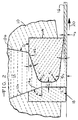
- FIG. 1 The present invention is generally illustrated in FIG. 1 wherein a casting system is shown as including a ladle 8 which includes a stopper rod 9 for controlling the flow of molten material 12 into a tundish or reservoir 10.
- Molten material 12 is supplied to a casting nozzle 14 for producing cast strip 16 on a rotating substrate 18 which is cooled and rotates in direction 20.
- the nozzle is generally located at an angle before top dead center and typically about 5 to 90° before top dead center, and preferably about 15 to 60°.
- molten material 12 is fed to nozzle 14 through tundish walls 10 made of a suitable high temperature refractory material which are configured to improve the flow by providing a sloped angle A of about 15 to 90° and preferably about 45 to 75° to the nozzle gap G1 along rear tundish wall 10 a.
- the front tundish wall 10 b is generally configured at an angle of about 15 to 90° and preferably sloped from 60 to 90° and is represented by angle D in FIG. 2.
- Nozzle 14 made from a refractory such as boron nitride, has a rear nozzle wall 14a which is normally an extension of rear tundish wall 10a with the same general slope.
- the front nozzle wall 14b is a more gradual slope with an angle of about 10 to 45 ° and typically about 15 to 30°. This slope is identified as angle B in the drawing. The combination of slopes in these walls produces a smooth flow of molten metal into the nozzle 14.
- the upper shoulder of nozzle 14b has further been shown to improve molten flow when the nozzle is rounded as shown by r1.
- the rounding of the shoulders in the nozzle design also reduces turbulence in the stream, reduces clogging in the the slot, reduces breakage and wear of the nozzle and produces a more uniform cast strip.
- the slope of the nozzle walls also improves heat transfer from the melt to the nozzle area near the substrate since the thickness is reduced and this helps to reduce freezing.
- the gap G1 between nozzle walls 14a and 14b is about 0.01 to about 0.3 inches and typically about 0.05 to 0.10 inches for casting strip of about 0.03 to 0.05 inches.
- the length of the slot may vary but successful casting trials have resulted with a length of about 0.25 to about 0.5 inches.
- the front nozzle wall 14b has a lower rounded portion identified by r2 which improves the flow of the stream and strip uniformity. The rounding of the nozzle portions r1 and r2 will also reduce wear and breakage in these areas.
- the distance between the lower portion of front wall 14b and substrate is determined based on the balance between the casting parameters and the desired strip thickness and identified as G2 in the drawing.
- G2 is determined by the relationship to the size of G3 and the converging angle C used.
- the present nozzle system provides a method and apparatus for controlling a molten stream being removed by a rotating substrate.
- the pulling action provided by the rotational speed of a substrate such as a wheel, drum or belt, provides a flow pattern or spreading action which must be counteracted by a molten metal flow pattern through the casting nozzle.
- An increase in static head pressure would increase the flow rate but this approach tends to increase turbulence and cause flow patterns which have an adverse influence on surface quality.
- the flow of molten material through the nozzle has an important influence on the flow onto the substrate and this understanding has not been completely understood in the past.
- the present invention has found that restricting the flow through the nozzle tends to produce a flatter stream which is more uniform and beneficial to control of the cast strip.
- pressurized flow from the casting nozzle allows a greater flexibility to increase the angle before top dead center of the substrate. Moving further back from the top of the substrate produces a casting process with a longer contact time between the molten material and the substrate for a given rotational speed of the substrate. The longer contact with the substrate increases the overall ability to extract heat during solidification.
- the approach angle A has been found to improve the smoothness of the flow exiting from the nozzle, particularly in comparison with nozzles having a perpendicular approach angle.
- gaps G1, G2 and G3 are very critical to the obtaining of improved flow and more uniform strip.
- gap G1 is greater than gap G3, the tendency for molten metal back flow is far more controllable.
- the narrow steam produced at G3 is more controlled and uniform.
- This gap relationship provided a full channel in the nozzle and constant melt contact with the nozzle roof.
- the melt contact with the roof at G3 produces a more uniform flow and a more uniform cast product. If the roof contact by the molten metal is intermittent, it causes fluctuations in the stream and a nonuniform cast strip. Restrictive flow through the nozzle tends to reduce the tendency for stream thinning and high flow regions in the center of the strip being cast. Restrictive flow also tends to minimize stream edge effects.
- Molten low carbon steel with a ferrostatic head of 16 inches and a casting temperature of about 2880° F was cast on a 7 foot diameter copper wheel.
- the nozzle slot G1 was 0.10 inches.
- the substrate speed was varied between 2 to 20 feet per minute to evaluate the various nozzle parameters and their influence on flow rates and strip quality.
- Uniform cast strip of about 3 inches wide and about 0.035 to 0.04 inches thick was produced with the converging nozzles of the present invention with the approach angle of the delivery and casting position on the wheel according to the present invention.
- the nozzle designs having a gap G3 greater than G1 did not produce the desired flow conditions and strip quality due to the gap relationship of the present invention.
Landscapes
- Engineering & Computer Science (AREA)
- Mechanical Engineering (AREA)
- Continuous Casting (AREA)
- Casting Support Devices, Ladles, And Melt Control Thereby (AREA)
- Coating With Molten Metal (AREA)
- Telephone Function (AREA)
- Yarns And Mechanical Finishing Of Yarns Or Ropes (AREA)
- Formation And Processing Of Food Products (AREA)
Applications Claiming Priority (2)
| Application Number | Priority Date | Filing Date | Title |
|---|---|---|---|
| US543613 | 1990-06-22 | ||
| US07/543,613 US5063988A (en) | 1990-06-22 | 1990-06-22 | Method and apparatus for strip casting |
Publications (3)
| Publication Number | Publication Date |
|---|---|
| EP0463223A2 true EP0463223A2 (de) | 1992-01-02 |
| EP0463223A3 EP0463223A3 (en) | 1992-12-02 |
| EP0463223B1 EP0463223B1 (de) | 2002-01-09 |
Family
ID=24168783
Family Applications (1)
| Application Number | Title | Priority Date | Filing Date |
|---|---|---|---|
| EP90118969A Expired - Lifetime EP0463223B1 (de) | 1990-06-22 | 1990-10-04 | Verfahren und Einrichtung zum Bandstranggiessen |
Country Status (11)
| Country | Link |
|---|---|
| US (1) | US5063988A (de) |
| EP (1) | EP0463223B1 (de) |
| JP (1) | JP2678191B2 (de) |
| KR (1) | KR100194090B1 (de) |
| AT (1) | ATE211664T1 (de) |
| AU (1) | AU634820B2 (de) |
| BR (1) | BR9004833A (de) |
| CA (1) | CA2026726C (de) |
| DE (1) | DE69033895T2 (de) |
| DK (1) | DK0463223T3 (de) |
| ES (1) | ES2165837T3 (de) |
Families Citing this family (7)
| Publication number | Priority date | Publication date | Assignee | Title |
|---|---|---|---|---|
| DE4407873C2 (de) * | 1994-03-04 | 1997-04-10 | Mannesmann Ag | Verfahren und Vorrichtung zum Kühlen schmelzflüssigen Stahls |
| DE69630647T2 (de) * | 1995-09-26 | 2004-09-30 | Sharp K.K. | Antriebsvorrichtung für lichtempfindliche Trommel |
| US5827439A (en) * | 1995-12-27 | 1998-10-27 | Nippon Steel Corporation | Supplying method for molten alloy for producing amorphous alloy thin strip |
| JPH10133442A (ja) * | 1996-10-30 | 1998-05-22 | Nec Niigata Ltd | 画像形成装置のpcカートリッジ |
| JP3643089B2 (ja) * | 2002-05-01 | 2005-04-27 | 三菱電機株式会社 | ノズル |
| EP1897634B8 (de) * | 2005-06-13 | 2017-08-09 | Sintokogio, Ltd. | Vorrichtung zum formen eines formkastenfreien oberen und unteren giesswerkzeugs |
| CN107234218B (zh) * | 2016-06-27 | 2022-10-18 | 安泰科技股份有限公司 | 用于制备非晶带材的熔潭内嵌式喷嘴 |
Family Cites Families (15)
| Publication number | Priority date | Publication date | Assignee | Title |
|---|---|---|---|---|
| US4142571A (en) * | 1976-10-22 | 1979-03-06 | Allied Chemical Corporation | Continuous casting method for metallic strips |
| US4221257A (en) * | 1978-10-10 | 1980-09-09 | Allied Chemical Corporation | Continuous casting method for metallic amorphous strips |
| US4484614A (en) * | 1980-05-09 | 1984-11-27 | Allegheny Ludlum Steel Corporation | Method of and apparatus for strip casting |
| AU6997681A (en) * | 1980-05-09 | 1981-11-12 | Allegheny Ludlum Steel Corp. | Nozzle |
| US4617981A (en) * | 1980-05-09 | 1986-10-21 | Battelle Development Corporation | Method and apparatus for strip casting |
| US4475583A (en) * | 1980-05-09 | 1984-10-09 | Allegheny Ludlum Steel Corporation | Strip casting nozzle |
| US4479528A (en) * | 1980-05-09 | 1984-10-30 | Allegheny Ludlum Steel Corporation | Strip casting apparatus |
| US4399860A (en) * | 1980-10-03 | 1983-08-23 | Allegheny Ludlum Steel Corporation | Apparatus for strip casting |
| US4485839A (en) * | 1980-10-22 | 1984-12-04 | Allegheny Ludlum Steel Corporation | Rapidly cast alloy strip having dissimilar portions |
| GB2112913B (en) * | 1981-12-31 | 1985-02-06 | Energy Conversion Devices Inc | Melt spinning crucible |
| GB8327830D0 (en) * | 1983-10-18 | 1983-11-16 | Ae Plc | Continuous strip |
| DE3423834A1 (de) * | 1984-06-28 | 1986-01-09 | Mannesmann AG, 4000 Düsseldorf | Verfahren und vorrichtung zum kontinuierlichen giessen von metallschmelze, insbesondere von stahlschmelze |
| US4768458A (en) * | 1985-12-28 | 1988-09-06 | Hitachi, Metals Inc. | Method of producing thin metal ribbon |
| JPS6358664A (ja) * | 1986-08-29 | 1988-03-14 | Sony Corp | デイジタル磁気再生装置 |
| US4771820A (en) * | 1987-11-30 | 1988-09-20 | Westinghouse Electric Corp. | Strip casting apparatus and method |
-
1990
- 1990-06-22 US US07/543,613 patent/US5063988A/en not_active Expired - Fee Related
- 1990-09-25 KR KR1019900015177A patent/KR100194090B1/ko not_active Expired - Fee Related
- 1990-09-25 AU AU63205/90A patent/AU634820B2/en not_active Ceased
- 1990-09-26 BR BR909004833A patent/BR9004833A/pt not_active IP Right Cessation
- 1990-10-02 CA CA002026726A patent/CA2026726C/en not_active Expired - Fee Related
- 1990-10-04 EP EP90118969A patent/EP0463223B1/de not_active Expired - Lifetime
- 1990-10-04 DK DK90118969T patent/DK0463223T3/da active
- 1990-10-04 DE DE69033895T patent/DE69033895T2/de not_active Expired - Fee Related
- 1990-10-04 AT AT90118969T patent/ATE211664T1/de not_active IP Right Cessation
- 1990-10-04 ES ES90118969T patent/ES2165837T3/es not_active Expired - Lifetime
- 1990-11-16 JP JP2308975A patent/JP2678191B2/ja not_active Expired - Fee Related
Also Published As
| Publication number | Publication date |
|---|---|
| ATE211664T1 (de) | 2002-01-15 |
| KR100194090B1 (ko) | 1999-06-15 |
| AU6320590A (en) | 1992-01-02 |
| DE69033895D1 (de) | 2002-02-14 |
| BR9004833A (pt) | 1991-12-24 |
| AU634820B2 (en) | 1993-03-04 |
| EP0463223B1 (de) | 2002-01-09 |
| DE69033895T2 (de) | 2002-08-22 |
| ES2165837T3 (es) | 2002-04-01 |
| US5063988A (en) | 1991-11-12 |
| CA2026726C (en) | 2002-02-19 |
| JPH0455043A (ja) | 1992-02-21 |
| KR920000408A (ko) | 1992-01-29 |
| EP0463223A3 (en) | 1992-12-02 |
| JP2678191B2 (ja) | 1997-11-17 |
| DK0463223T3 (da) | 2002-02-11 |
| CA2026726A1 (en) | 1991-12-23 |
Similar Documents
| Publication | Publication Date | Title |
|---|---|---|
| US4751957A (en) | Method of and apparatus for continuous casting of metal strip | |
| US5063988A (en) | Method and apparatus for strip casting | |
| US4351384A (en) | Coolant control in EM casting | |
| US4290476A (en) | Nozzle geometry for planar flow casting of metal ribbon | |
| US4274473A (en) | Contour control for planar flow casting of metal ribbon | |
| DE69030082T2 (de) | Verfahren und Vorrichtung für den Schmelzfluss beim Bandstranggiessen | |
| US4572280A (en) | Process for cooling a continuously cast ingot during casting | |
| US5063989A (en) | Method and apparatus for planar drag strip casting | |
| US3931848A (en) | Method and apparatus for cooling a strand cast in an oscillating mold during continuous casting of metals, especially steel | |
| US4790368A (en) | Method of manufacturing thin metal sheet directly from molten metal and apparatus for manufacturing same | |
| JPS6015049A (ja) | 連続鋳造装置 | |
| KR100443113B1 (ko) | 금속스트립의주조장치및주조방법 | |
| EP0040073B1 (de) | Vorrichtung zum Giessen eines Streifens | |
| EP0387271B1 (de) | Verfahren und vorrichtung zum direkten giessen von metall zur bildung langer körper | |
| US6857465B2 (en) | Method for the production of a continously-cast precursor | |
| WO1987002285A1 (en) | Method of and apparatus for continuous casting of metal strip | |
| Follstaedt et al. | Method and apparatus for strip casting | |
| CA1281167C (en) | Wire casting | |
| GB2148764A (en) | Method and apparatus for casting a continuous strip | |
| US20080257524A1 (en) | Delivery Device and Method for Using the Same | |
| US4942918A (en) | Controlled-flow fiber casting | |
| JPH0512059B2 (de) | ||
| Schenk et al. | Process for the Continuous Casting of a Metal Strand, Especially as a Band or Profile, and Device for Carrying Out the Process | |
| NZ199651A (en) | Coolant control in continuous electromagnetic casting using two converging coolant streams | |
| JPS642763A (en) | Production of metal wire |
Legal Events
| Date | Code | Title | Description |
|---|---|---|---|
| PUAI | Public reference made under article 153(3) epc to a published international application that has entered the european phase |
Free format text: ORIGINAL CODE: 0009012 |
|
| AK | Designated contracting states |
Kind code of ref document: A2 Designated state(s): AT BE CH DE DK ES FR GB GR IT LI LU NL SE |
|
| PUAL | Search report despatched |
Free format text: ORIGINAL CODE: 0009013 |
|
| AK | Designated contracting states |
Kind code of ref document: A3 Designated state(s): AT BE CH DE DK ES FR GB GR IT LI LU NL SE |
|
| 17P | Request for examination filed |
Effective date: 19930521 |
|
| 17Q | First examination report despatched |
Effective date: 19931008 |
|
| GRAG | Despatch of communication of intention to grant |
Free format text: ORIGINAL CODE: EPIDOS AGRA |
|
| GRAG | Despatch of communication of intention to grant |
Free format text: ORIGINAL CODE: EPIDOS AGRA |
|
| GRAH | Despatch of communication of intention to grant a patent |
Free format text: ORIGINAL CODE: EPIDOS IGRA |
|
| GRAH | Despatch of communication of intention to grant a patent |
Free format text: ORIGINAL CODE: EPIDOS IGRA |
|
| ITF | It: translation for a ep patent filed | ||
| GRAA | (expected) grant |
Free format text: ORIGINAL CODE: 0009210 |
|
| REG | Reference to a national code |
Ref country code: GB Ref legal event code: IF02 |
|
| AK | Designated contracting states |
Kind code of ref document: B1 Designated state(s): AT BE CH DE DK ES FR GB GR IT LI LU NL SE |
|
| REF | Corresponds to: |
Ref document number: 211664 Country of ref document: AT Date of ref document: 20020115 Kind code of ref document: T |
|
| REG | Reference to a national code |
Ref country code: CH Ref legal event code: NV Representative=s name: MICHELI & CIE INGENIEURS-CONSEILS Ref country code: CH Ref legal event code: EP |
|
| REG | Reference to a national code |
Ref country code: DK Ref legal event code: T3 |
|
| REF | Corresponds to: |
Ref document number: 69033895 Country of ref document: DE Date of ref document: 20020214 |
|
| REG | Reference to a national code |
Ref country code: ES Ref legal event code: FG2A Ref document number: 2165837 Country of ref document: ES Kind code of ref document: T3 |
|
| REG | Reference to a national code |
Ref country code: GR Ref legal event code: EP Ref document number: 20020401368 Country of ref document: GR |
|
| PGFP | Annual fee paid to national office [announced via postgrant information from national office to epo] |
Ref country code: FR Payment date: 20020918 Year of fee payment: 13 |
|
| PGFP | Annual fee paid to national office [announced via postgrant information from national office to epo] |
Ref country code: SE Payment date: 20020919 Year of fee payment: 13 Ref country code: NL Payment date: 20020919 Year of fee payment: 13 Ref country code: AT Payment date: 20020919 Year of fee payment: 13 |
|
| PGFP | Annual fee paid to national office [announced via postgrant information from national office to epo] |
Ref country code: DK Payment date: 20020920 Year of fee payment: 13 |
|
| PGFP | Annual fee paid to national office [announced via postgrant information from national office to epo] |
Ref country code: LU Payment date: 20020926 Year of fee payment: 13 |
|
| PGFP | Annual fee paid to national office [announced via postgrant information from national office to epo] |
Ref country code: GR Payment date: 20020927 Year of fee payment: 13 Ref country code: GB Payment date: 20020927 Year of fee payment: 13 |
|
| PGFP | Annual fee paid to national office [announced via postgrant information from national office to epo] |
Ref country code: CH Payment date: 20021023 Year of fee payment: 13 Ref country code: BE Payment date: 20021023 Year of fee payment: 13 |
|
| PGFP | Annual fee paid to national office [announced via postgrant information from national office to epo] |
Ref country code: DE Payment date: 20021031 Year of fee payment: 13 |
|
| PGFP | Annual fee paid to national office [announced via postgrant information from national office to epo] |
Ref country code: ES Payment date: 20021106 Year of fee payment: 13 |
|
| PLBE | No opposition filed within time limit |
Free format text: ORIGINAL CODE: 0009261 |
|
| STAA | Information on the status of an ep patent application or granted ep patent |
Free format text: STATUS: NO OPPOSITION FILED WITHIN TIME LIMIT |
|
| 26N | No opposition filed | ||
| PG25 | Lapsed in a contracting state [announced via postgrant information from national office to epo] |
Ref country code: LU Free format text: LAPSE BECAUSE OF NON-PAYMENT OF DUE FEES Effective date: 20031004 Ref country code: GB Free format text: LAPSE BECAUSE OF NON-PAYMENT OF DUE FEES Effective date: 20031004 Ref country code: AT Free format text: LAPSE BECAUSE OF NON-PAYMENT OF DUE FEES Effective date: 20031004 |
|
| PG25 | Lapsed in a contracting state [announced via postgrant information from national office to epo] |
Ref country code: SE Free format text: LAPSE BECAUSE OF NON-PAYMENT OF DUE FEES Effective date: 20031005 |
|
| PG25 | Lapsed in a contracting state [announced via postgrant information from national office to epo] |
Ref country code: ES Free format text: LAPSE BECAUSE OF NON-PAYMENT OF DUE FEES Effective date: 20031006 |
|
| PG25 | Lapsed in a contracting state [announced via postgrant information from national office to epo] |
Ref country code: LI Free format text: LAPSE BECAUSE OF NON-PAYMENT OF DUE FEES Effective date: 20031031 Ref country code: CH Free format text: LAPSE BECAUSE OF NON-PAYMENT OF DUE FEES Effective date: 20031031 Ref country code: BE Free format text: LAPSE BECAUSE OF NON-PAYMENT OF DUE FEES Effective date: 20031031 |
|
| BERE | Be: lapsed |
Owner name: *ARMCO INC. Effective date: 20031031 |
|
| PG25 | Lapsed in a contracting state [announced via postgrant information from national office to epo] |
Ref country code: DK Free format text: LAPSE BECAUSE OF NON-PAYMENT OF DUE FEES Effective date: 20040430 |
|
| PG25 | Lapsed in a contracting state [announced via postgrant information from national office to epo] |
Ref country code: NL Free format text: LAPSE BECAUSE OF NON-PAYMENT OF DUE FEES Effective date: 20040501 Ref country code: DE Free format text: LAPSE BECAUSE OF NON-PAYMENT OF DUE FEES Effective date: 20040501 |
|
| PG25 | Lapsed in a contracting state [announced via postgrant information from national office to epo] |
Ref country code: GR Free format text: LAPSE BECAUSE OF NON-PAYMENT OF DUE FEES Effective date: 20040504 |
|
| GBPC | Gb: european patent ceased through non-payment of renewal fee |
Effective date: 20031004 |
|
| EUG | Se: european patent has lapsed | ||
| REG | Reference to a national code |
Ref country code: DK Ref legal event code: EBP |
|
| REG | Reference to a national code |
Ref country code: CH Ref legal event code: PL |
|
| PG25 | Lapsed in a contracting state [announced via postgrant information from national office to epo] |
Ref country code: FR Free format text: LAPSE BECAUSE OF NON-PAYMENT OF DUE FEES Effective date: 20040630 |
|
| NLV4 | Nl: lapsed or anulled due to non-payment of the annual fee |
Effective date: 20040501 |
|
| REG | Reference to a national code |
Ref country code: FR Ref legal event code: ST |
|
| REG | Reference to a national code |
Ref country code: ES Ref legal event code: FD2A Effective date: 20031006 |
|
| PG25 | Lapsed in a contracting state [announced via postgrant information from national office to epo] |
Ref country code: IT Free format text: LAPSE BECAUSE OF NON-PAYMENT OF DUE FEES;WARNING: LAPSES OF ITALIAN PATENTS WITH EFFECTIVE DATE BEFORE 2007 MAY HAVE OCCURRED AT ANY TIME BEFORE 2007. THE CORRECT EFFECTIVE DATE MAY BE DIFFERENT FROM THE ONE RECORDED. Effective date: 20051004 |