EP0463253A1 - Verfahren zur Migration seismischer Daten - Google Patents
Verfahren zur Migration seismischer Daten Download PDFInfo
- Publication number
- EP0463253A1 EP0463253A1 EP90307119A EP90307119A EP0463253A1 EP 0463253 A1 EP0463253 A1 EP 0463253A1 EP 90307119 A EP90307119 A EP 90307119A EP 90307119 A EP90307119 A EP 90307119A EP 0463253 A1 EP0463253 A1 EP 0463253A1
- Authority
- EP
- European Patent Office
- Prior art keywords
- velocity
- seismic data
- elevation
- migration
- data
- Prior art date
- Legal status (The legal status is an assumption and is not a legal conclusion. Google has not performed a legal analysis and makes no representation as to the accuracy of the status listed.)
- Granted
Links
- 238000000034 method Methods 0.000 title claims abstract description 84
- 238000013508 migration Methods 0.000 claims abstract description 110
- 230000005012 migration Effects 0.000 claims abstract description 108
- 230000001788 irregular Effects 0.000 claims abstract description 29
- 238000003384 imaging method Methods 0.000 claims description 7
- XLYOFNOQVPJJNP-UHFFFAOYSA-N water Substances O XLYOFNOQVPJJNP-UHFFFAOYSA-N 0.000 abstract description 35
- 238000012937 correction Methods 0.000 description 20
- 239000010410 layer Substances 0.000 description 20
- 238000012545 processing Methods 0.000 description 16
- 230000008569 process Effects 0.000 description 8
- 230000009471 action Effects 0.000 description 5
- 230000000694 effects Effects 0.000 description 5
- 230000008859 change Effects 0.000 description 4
- 230000008901 benefit Effects 0.000 description 3
- 238000007598 dipping method Methods 0.000 description 3
- 230000006870 function Effects 0.000 description 3
- 238000004364 calculation method Methods 0.000 description 2
- 239000013049 sediment Substances 0.000 description 2
- 230000035945 sensitivity Effects 0.000 description 2
- 230000003068 static effect Effects 0.000 description 2
- 230000002411 adverse Effects 0.000 description 1
- 230000015556 catabolic process Effects 0.000 description 1
- 238000012790 confirmation Methods 0.000 description 1
- 238000006731 degradation reaction Methods 0.000 description 1
- 230000001419 dependent effect Effects 0.000 description 1
- 239000006185 dispersion Substances 0.000 description 1
- 230000001747 exhibiting effect Effects 0.000 description 1
- 238000013213 extrapolation Methods 0.000 description 1
- 230000003116 impacting effect Effects 0.000 description 1
- 239000000463 material Substances 0.000 description 1
- 238000012986 modification Methods 0.000 description 1
- 230000004048 modification Effects 0.000 description 1
- 230000008450 motivation Effects 0.000 description 1
- 230000003287 optical effect Effects 0.000 description 1
- 238000003825 pressing Methods 0.000 description 1
- 230000000750 progressive effect Effects 0.000 description 1
- 230000004044 response Effects 0.000 description 1
- 238000012552 review Methods 0.000 description 1
- 238000005070 sampling Methods 0.000 description 1
- 239000002344 surface layer Substances 0.000 description 1
- 230000002123 temporal effect Effects 0.000 description 1
Images





Classifications
-
- G—PHYSICS
- G01—MEASURING; TESTING
- G01V—GEOPHYSICS; GRAVITATIONAL MEASUREMENTS; DETECTING MASSES OR OBJECTS; TAGS
- G01V1/00—Seismology; Seismic or acoustic prospecting or detecting
- G01V1/28—Processing seismic data, e.g. for interpretation or for event detection
- G01V1/30—Analysis
- G01V1/301—Analysis for determining seismic cross-sections or geostructures
Definitions
- This invention relates to seismic data processing and particularly to a method for migrating seismic data.
- Seismic surveys are conducted in a variety of environments and over a variety of terrains.
- the surveys are often conducted in regions having topographic relief on the orders of tens or hundreds of meters. Valleys, canyons, hills, and irregular water bottoms may cause distortion in the data.
- the data When the data are processed and displayed, the data have been time-adjusted as if the recording surface was horizontal. That is to say that surface irregularities associated with the topographic relief often are not handled properly in processing the data.
- Wave-equation datuming used in a manner known as “layer replacement”
- layer replacement may be used to image the irregular water bottom to a horizontal surface as proposed by Berryhill, but as mentioned earlier, this is an expensive procedure because of the computational time necessary to perform the calculations.
- wave theoretical depth migration Another technique which may be used is called “wave theoretical depth migration.” This technique has the disadvantages of being an expensive computation as well as being extremely sensitive to minor changes in migration velocity.
- Certain embodiments of the present invention can overcome the problems normally encountered in conventional seismic data pressing when elevation-static correcting the data and migrating. This method may be accomplished when using either finite-difference, f-k, or Kirchhoff migration techniques.
- seismic data located below the shifted datum, yet above the true or actual recording surface are migrated with the diffraction operator of the algorithm equal to zero.
- the algorithm samples the data, diffraction is unabled.
- the actual or selected migration velocity is input into the diffraction operator and the data are properly imaged.
- the overburden is migrated using the actual migration velocity.
- Data beneath the overburden is migrated with a velocity equal to zero, thus disabling the diffraction operator.
- these data simulate the data that would have been recorded at the boundary.
- Elevation-static correction may be performed as unconventional data processing. Data between the new datum and the original surface are migrated with the diffraction operator disabled. Sampling of velocity along or beneath the irregular surface reactivate the diffraction operator with the proper velocity and migration occurs.
- this method may provide a means of properly imaging that data in accordance with conventional data processing techniques at a fraction of the cost associated with computationally intensive techniques such as wave-equation datuming, layer replacement, or wave theoretical depth migration.
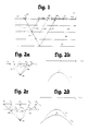
- FIG. 1 is a general illustration of how seismic data is collected.
- a seismic source 20 is located above or along the surface of the earth 22. Actuation of the source 20 imparts an acoustic signal 24 in the earth which radiates downward, impacting upon and passing through the various subsurface layers such as 26, 28 and 30. A portion 32 of signal 24 is reflected back towards the surface 20 by acoustic impedance changes between the adjacent subsurface layers.
- the reflected signals 32 arrive at the surface and are detected by a plurality of sensors 34 disposed along or above the surface of the earth 22.
- the received signals are converted by the sensors to electrical or optical signals which are transmitted to a remote recording unit 36 and stored on a archival storage medium such a magnetic tape.
- These seismic signals are recorded as a function of two-way travel time from the instant the acoustic source 20 is actuated.
- Figure 2a depicts the ray paths of a seismic signal from an exploding point source in the earth.
- the Figure also shows a common depth point or CDP gather of traces.
- the reflected signal 32 actually originated from a subsurface point 38.
- This model is well known to those skilled in the art as an "exploding reflector model.”
- the signal from the point source 38 should propagate as a spherical wave front in all directions.
- the rays 40 - 48 indicate the ray path, or normal of the acoustic signal to the spherical wave front, as it propagates towards the surface of the earth and receiver locations R; through R 5 on horizon E, .
- the resulting section of traces show the signals as a hyperbola or event S shown in Figure 2b.
- Migration of the event S. in Figure 2b should collapse the energy to a point P located at the apex of the hyperbola. If the incorrect migration velocity is chosen, event S will either be undermigrated, leaving downward limbs of the hyperbola, or overmigrated, inverting the limbs of the hyperbola to form a "smile.”
- Figure 2c illustrates receipt of the signals from point source 38 along a different elevation represented by horizon E 2 .
- the resulting section would appear as it does in Figure 2d.
- the expected seismic signal would approximate those shown on the traces of the section as the event S 2 .
- Superimposed with this Figure is the event from Figure 2b.
- the recording time of the apex of S 2 is greater than signal Si.
- the medium velocity is the same, the limbs of S 2 have less curvature because of the increased distance between the recording surface and the point scatterer 38.
- Migration of event S 2 using the same velocity as used in the previous example should result in the collapse of the energy to the same point P at the apex of the hyperbola.
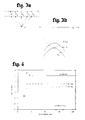
- FIGs 3a and 3b illustrate a conventional elevation-static correction and the seismic signals which would be received at horizon E, and datum horizon E 2 .
- a seismic signal from a CDP location 38 is received at sensor locations R, through R s located along horizon Ei.
- the data are corrected for elevation. That is to say the data are time-shifted with respect to a certain datum elevation. In this instance, the datuming is to a higher elevation E 2 .
- the elevation-static correction to the second horizon E 2 simulates receipt of the seismic signal at the second horizon, but does not provide for the lateral propagation across adjacent traces as does wave-equation datuming. This correction essentially pushes the energy from the CDP location downward in time.
- all of the traces have been time-adjusted by the same amount since the original elevation was horizontal.
- Figure 3b shows the resulting seismic signals as would be received on the traces at the two horizons.
- Event S is as it was in Figure 2b.
- the second event S 2 has not changed shape, but has been pushed downward in time. Migration of these events with the best estimated earth velocity will improperly migrate the event S 2 . If the migration velocity used in Figure 2b is applied to migrate the event S 2 in this Figure, the result will be an overmigration of the data as shown by the dashed hyperbola 50.
- the calculation of velocity which will best migrate elevation-static-corrected seismic data is a complex data-dependent procedure and is very seldom done in practice. Trial and error is the normal procedure.
- the elevation-static correction has essentially introduced an error and confused the timing relationships between the receiving locations and the source.
- elevation-static correction is a technique used by a majority of those in the seismic data processing industry. Although the technique introduces errors in the timing relationships in the data and requires trial and error to arrive at a correct migration velocity, the computational time needed to carry out the technique is a fraction of that necessary for the wave-equation datuming. There has been a long felt and yet unsolved need for a procedure to better migrate elevation-static corrected data without being as computationally intensive as wave-equation datuming.
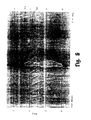
- Figure 4 is a constant velocity earth model displaying a horizontal surface or datum 52.
- Surface 52 represents the surface upon which the data are recorded.
- the row of horizontal line-segments 54 represent horizontal reflectors in the subsurface 56.
- the row of dipping line segments 58 represent non-horizontal reflectors.
- This model is similar to that shown in Figures 2a-d and represents the ideal situation which will be a benchmark for later comparison.
- Figure 5 is a zero-offset seismic section generated from the model in Figure 4.
- the ends of the line segments 54 and 58 have produced diffractions, some of which are identified as 60 and 62.
- Figure 6 is the result of a f-k migration of the zero-offset section of Figure 5.
- F-K migration is a constant velocity algorithm and produces very good results for the constant velocity model. All of the events represented by the segments 58 have been migrated properly. This is confirmed by the alignment of the events 58 with the flat events 54 directly above and a comparison with the model displayed in Figure 5.
- Figure 8 illustrates the second of the earth models to be examined.
- the Figure is a constant velocity earth model with a non-horizontal surface.
- the reflectors 54 and 58 are as they were in Figure 4. The only change is that the signals from the reflectors will be recorded along the sloping surface 64.
- Figure 9 illustrates a zero-offset section generated from the model in Figure 8.
- the most readily apparent difference from the zero-offset section shown in Figure 5 is the flat reflectors 54 are not recorded as flat events. This is because the signals took less time to reach the right portion of the recording surface than the signals on the left side of the Figure. Since the events are recorded on each trace as a function of travel time, the events slope downward to the left, illustrating the increased travel time to the sloping recording surface. As in the previous figures, the steeply dipping events have been displaced down dip and the diffractions are present.
- Figure 10 shows surface-recorded data extrapolated upward to a horizontal surface using wave-equation datuming.
- This output represents the theoretically correct way the data should move from the sloping surface 64 displayed in Figure 9 to another datum elevation.
- the sloping data in Figure 9 were extrapolated to a second elevation using wave-equation datuming.
- wave-equation datuming provides for lateral as well as vertical propagation of the energy from the reflectors. It is worth comparing the results of the wave-equation datuming to the results of the recorded signals along the flat datum shown in Figure 5.
- the curvature or the hyperbola are substantially the same in the two figures.
- Figure 11 is the result of f-k migration of the zero-offset, wave-equation datumed section in Figure 10. Again, because wave-equation datuming did not introduce errors in the timing relationships, the migration results are comparable to that achieved by f-k migration of the flat datum shown in Figure 6. Again, this is confirmation that lateral propagation of energy should occur when time-shifting to another elevation.
- Figure 12 is of surface-recorded data after application of elevation-static corrections upward to a flat datum.
- This figure illustrates what is conventionally done in seismic data processing today due to the computation expense of wave-equation datuming.
- Each of the traces in the figure have been time-shifted based upon the elevation difference between the recording surface and the desired flat datum.
- This Figure should be compared against the ideal model shown in Figure 5.
- differences should exist in the curvature between the signals recorded at the new datum and the signals recorded along the original surface.
- the diffraction hyperbola of the time-shifted signals in Figure 12 display greater curvature than the desired hyperbola in the model of Figure 5.
- the hyperbola having the greater amount of curvature are a direct result of the consequence of time shifting and not honoring the lateral propagation of the energy.
- Figures 13 through 15 are f-k migrations of the elevation-static corrected data of Figure 12 using percentages of the best estimated earth velocity.
- the diffraction hyperbola in the section have been overmigrated as evidenced by the concave upward diffractions.
- Figures 14 and 15 illustrate f-k migration results of the static corrected data using percentages of the true earth velocity used in Figure 13. Upon review of these two Figures, a major portion of the data has been improperly imaged. In Figure 14, the data on the left hand side have been undermigrated, while the data on the right hand side have been overmigrated.
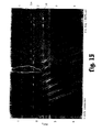
- Figure 15 is the result of a finite-difference migration conducted on the data in Figure 12. Here again the data have been improperly imaged when migrated with the best estimated velocity as in the previous examples.
- the entire section would have been migrated using velocities deemed representative of the earth beneath the datum elevation.
- the data would be improperly imaged.
- the migration velocity for the data between the time-shifted surface (new datum) and the original sloping surface 64 will be equal to (or very close to) zero.
- zero velocity in the migration algorithm disables the diffraction operator in the algorithm, and thus no migration is performed on that portion of the data.
- the migration velocity becomes the best estimated earth velocity, enabling diffraction and migration occurs.
- the fifteen degree depth-migration may be expressed: where a; is temporal frequency, x and z are spatial coordinates, Q is the pressure wave field transformed in time and v( x , z) is the earth velocity extended to define velocity between the recording surface and the datum.
- migration with Equation (1) is done by alternately applying the two terms on the righthand side using the split system of Equations (2) and (3):
- Equation (2) is to collapse diffractions and is often referred to as the diffraction equation;
- Equation (3) the so-called thin-lens equation, is to differentially time-shift data traces based on lateral variations in the interval-velocity field.
- Equation (5) the thin-lens equation, within this layer is to remove the elevation-static correction that was previously applied.
- the velocity in Equation (4) then reverts to the best estimate of the true subsurface interval velocity.
- the migration-velocity below the recording surface is governed solely by the subsurface geology; it does not require any artificial adjustments caused by the inability of elevation-static corrections to represent wave propagation between the recording surface and datum. This may be explained better by referring to Figure 17.
- Figure 17 displays the relationships between the original sloping surface 64 where the data were recorded, the elevation-static corrected datum surface E d , and the zone of actual data D A .
- migration is performed as a series of downward continuations DC n , each represented by the dashed lines, where n represents the successive downward-continuation horizon.
- the concept of downward continuation in migration algorithms is a known process and will not be explained herein.
- the algorithm simulates the seismic signal as received at the new surface DC n using the appropriate migration velocity. If we apply the improved migration method to the data depicted in Figure 17, at each migration (downward continuation) step(s) in the shifted zone, the migration velocity equals zero and thus no migration occurs.
- Figure 18 illustrates the results of a finite-difference migration using a method embodying the invention.
- the migration method described above also has application to situations where a curved or irregular boundary between different velocity mediums exists below the recording surface.
- a common example of such a situation is shown is Figure 19.
- the Figure illustrates a situation which is often encountered in marine seismic exploration.
- the upper horizontal surface 68 represents the water surface.
- Surface 70 represents the water bottom having a canyon or other depression having some topographic variation.
- Surfaces 72-76 represent subsurface reflectors, each having a subsurface velocity V n , where n designates a velocity characteristic for that layer.
- Lines 78-84 represent the ray paths followed by an acoustic signal as it is reflected from layer 72, passing through layer 70 and up to the water surface 68.
- seismic data processors typically used one of two methods.
- the first method to be discussed is called “layer replacement.”
- the technique is used throughout the industry and is well known to one of ordinary skill in the art.
- the data recorded at the surface are used as input and through the wave equation, simulate what would have been recorded at the water bottom. This in essence provides a display as if the sensors were located along the irregular water bottom.
- the data are then extrapolated back to the surface using wave-equation datuming, but the water velocity is replaced with the velocity of the subsurface layers.
- the step may be applied both pre-stack and post-stack.
- this technique is again computationally expensive.
- Wave theoretical depth migration Another technique used to solve the irregular water bottom problem is called “wave theoretical depth migration.” This technique was developed to handle data situations where the velocity of the subsurface vanes laterally. However, there are two characteristics with depth migration which make the technique less used. The first is that the technique is computationally extensive. The other is that the output image is extremely sensitive to minor changes in the input migration velocity. Thus what happens in performing a depth migration is that the process is repeated several times, each time using an updated velocity field until the appropriate image is obtained. Because of the sensitivity of the algorithm, each time the migration needs to be redone, the cost increases accordingly.
- the situation described above may be properly migrated without the sensitivity problems and at least one-half the cost.
- This process may be accomplished using any conventional migration technique.
- our procedure migrates the seismic data above the water bottom with the appropriate migration velocity. Below the water bottom, the migration velocity is set to zero. The output from this migration correctly images the water bottom. The data below the water bottom are partially migrated; that near the surface more completely than the data progressively deeper in the section. At this point, the resulting image is nearly like the image obtained if we conducted wave-equation datuming from the water surface 68 down to the water bottom 70.
- the water bottom represents the surface where the signals were recorded, i.e., the reflection of the water bottom is still located down in time and should be at zero time if indeed it represents the recording surface.
- a time shift must be applied to the data to bring the water bottom reflection to time zero.
- the output of this procedure is identical to wave-equation datuming to the water bottom if the water bottom was flat. This brings us back to the problem encountered in land data processing discussed above where data is recorded along an irregular surface and time shifted to some other flat datum.
- the procedure used from this point is to migrate the data below the datum, and above the actual data, with a migration velocity of zero. The best estimated earth velocity is used once the migration algorithm encounters data below the time-shift zone as described above.
- DMO dip move out
- the zero-velocity layer offers significant improvements over conventional migration of elevation-static corrected data. It is exact when the surface of the earth is locally flat and, regardless of the magnitude of elevation change within the survey; it is highly accurate so long as elevation changes are smooth.
- the zero-velocity concept may also be used for efficient wave-equation datuming and layer-replacement techniques.
Landscapes
- Engineering & Computer Science (AREA)
- Remote Sensing (AREA)
- Physics & Mathematics (AREA)
- Life Sciences & Earth Sciences (AREA)
- Acoustics & Sound (AREA)
- Environmental & Geological Engineering (AREA)
- Geology (AREA)
- General Life Sciences & Earth Sciences (AREA)
- General Physics & Mathematics (AREA)
- Geophysics (AREA)
- Geophysics And Detection Of Objects (AREA)
Priority Applications (1)
| Application Number | Priority Date | Filing Date | Title |
|---|---|---|---|
| DE69012111T DE69012111D1 (de) | 1990-06-28 | 1990-06-28 | Verfahren zur Migration seismischer Daten. |
Applications Claiming Priority (1)
| Application Number | Priority Date | Filing Date | Title |
|---|---|---|---|
| US07/363,666 US4943950A (en) | 1989-05-26 | 1989-05-26 | Method for migrating seismic data |
Publications (2)
| Publication Number | Publication Date |
|---|---|
| EP0463253A1 true EP0463253A1 (de) | 1992-01-02 |
| EP0463253B1 EP0463253B1 (de) | 1994-08-31 |
Family
ID=23431170
Family Applications (1)
| Application Number | Title | Priority Date | Filing Date |
|---|---|---|---|
| EP90307119A Expired - Lifetime EP0463253B1 (de) | 1989-05-26 | 1990-06-28 | Verfahren zur Migration seismischer Daten |
Country Status (3)
| Country | Link |
|---|---|
| US (1) | US4943950A (de) |
| EP (1) | EP0463253B1 (de) |
| AU (1) | AU640665B2 (de) |
Cited By (1)
| Publication number | Priority date | Publication date | Assignee | Title |
|---|---|---|---|---|
| GB2380284A (en) * | 2001-07-09 | 2003-04-02 | Pgs Americas Inc | Extended recursive f-k migration |
Families Citing this family (21)
| Publication number | Priority date | Publication date | Assignee | Title |
|---|---|---|---|---|
| US5229938A (en) * | 1989-06-28 | 1993-07-20 | Conoco Inc. | Method for migrating seismic data by using ray tracing in determining two way travel times |
| US5097452A (en) * | 1991-05-21 | 1992-03-17 | Western Atlas International, Inc. | Analysis of migration velocity by migration of velocity spectra |
| US5530679A (en) * | 1993-05-10 | 1996-06-25 | Western Atlas International, Inc. | Method for migrating seismic data |
| US5502687A (en) * | 1993-07-01 | 1996-03-26 | Western Atlas International, Inc. | Method for datumizing seismic data by forward modeling |
| US5515335A (en) * | 1993-08-16 | 1996-05-07 | Atlantic Richfield Company | Seismic trace overburden correction method |
| US5629905A (en) * | 1993-09-24 | 1997-05-13 | Exxon Production Research Company | Method of datuming seismic data and method of processing seismic data |
| USH1529H (en) * | 1993-10-12 | 1996-05-07 | Exxon Production Research Company | Method for wave equation velocity replacement of the low-velocity-layer in seismic data processing |
| US5629904A (en) * | 1994-11-30 | 1997-05-13 | Paradigm Geophysical, Ltd. | Migration process using a model based aperture technique |
| US5719822A (en) * | 1996-10-04 | 1998-02-17 | Vector Seismic Data Processing, Inc. | Seismic data radon dip moveout method |
| US5999488A (en) * | 1998-04-27 | 1999-12-07 | Phillips Petroleum Company | Method and apparatus for migration by finite differences |
| US6687659B1 (en) | 2000-03-24 | 2004-02-03 | Conocophillips Company | Method and apparatus for absorbing boundary conditions in numerical finite-difference acoustic applications |
| US6894949B2 (en) * | 2002-10-04 | 2005-05-17 | Baker Hughes Incorporated | Walkaway tomographic monitoring |
| WO2004063770A1 (en) * | 2003-01-06 | 2004-07-29 | Pgs Americas, Inc. | Method for quantifying water column timing and amplitude anomalies in a 3 dimensional seismic survey |
| PL2441412T3 (pl) | 2005-09-16 | 2015-04-30 | Mehrhof Implant Tech Gmbh | Dwuczęściowy implant zębowy |
| US7626886B2 (en) * | 2006-06-06 | 2009-12-01 | Baker Hughes Incorporated | P-wave anisotropy determination using borehole measurements |
| NO20083861L (no) * | 2007-09-14 | 2009-03-16 | Geco Technology Bv | Bruk av kildehoydemalinger for a fjerne sjoforstyrrelser |
| CN103777237B (zh) * | 2012-10-17 | 2016-12-21 | 中国石油化工股份有限公司 | 一种基于空变加权镶边波数域滤波的地表高程平滑方法 |
| US9310500B2 (en) * | 2013-02-20 | 2016-04-12 | Chevron U.S.A. Inc. | Velocity models for processing seismic data based on basin modeling |
| US10754050B2 (en) | 2017-03-31 | 2020-08-25 | Chevron U.S.A. Inc. | Pore pressure prediction based on an integrated seismic and basin modeling approach |
| CN111755903B (zh) * | 2017-06-23 | 2022-08-30 | 上海电巴新能源科技有限公司 | 电连接装置 |
| US12000971B2 (en) * | 2021-12-10 | 2024-06-04 | Saudi Arabian Oil Company | Method and system for seismic processing using virtual trace bins based on offset attributes and azimuthal attributes |
Citations (4)
| Publication number | Priority date | Publication date | Assignee | Title |
|---|---|---|---|---|
| US3353151A (en) * | 1964-09-30 | 1967-11-14 | Texas Instruments Inc | Common tangent stacking method and system for locating sonic energy velocity discontinuities |
| US4069471A (en) * | 1976-03-12 | 1978-01-17 | Geophysical Systems Corporation | Method of determining weathering corrections in seismic record processing |
| US4577298A (en) * | 1983-09-08 | 1986-03-18 | Mobil Oil Corporation | Method for correcting surface consistent statics in seismic traces |
| US4577297A (en) * | 1983-04-27 | 1986-03-18 | Mobil Oil Corporation | Method for enhancing recorded marine seismic reflection signals having undulating water bottom distortions |
Family Cites Families (10)
| Publication number | Priority date | Publication date | Assignee | Title |
|---|---|---|---|---|
| US482A (en) * | 1837-11-25 | Improvement in spring-saddles | ||
| US4355379A (en) * | 1968-10-16 | 1982-10-19 | Chevron Research Company | Continuous automatic migration of seismic data with waveform preservation |
| US3539982A (en) * | 1969-03-03 | 1970-11-10 | Texas Instruments Inc | Method and apparatus for consistent static correction of common depth point seismic signals |
| US3611278A (en) * | 1969-07-17 | 1971-10-05 | Mobil Oil Corp | Interval velocity determination |
| US4464737A (en) * | 1981-09-28 | 1984-08-07 | Mobil Oil Corporation | Method for migration of seismic reflection waves |
| US4479205A (en) * | 1981-11-16 | 1984-10-23 | Mobil Oil Corporation | Method of migrating seismic data without dependency on velocity |
| US4742497A (en) * | 1985-11-18 | 1988-05-03 | Western Atlas International, Inc. | Method of processing seismic data |
| US4797861A (en) * | 1985-11-18 | 1989-01-10 | Western Atlas International, Inc. | Method of processing seismic data |
| US4745585A (en) * | 1986-04-03 | 1988-05-17 | Western Atlas International, Inc. | Method of migrating seismic data |
| USH482H (en) | 1986-10-20 | 1988-06-07 | Seismic migration method |
-
1989
- 1989-05-26 US US07/363,666 patent/US4943950A/en not_active Expired - Lifetime
-
1990
- 1990-06-28 EP EP90307119A patent/EP0463253B1/de not_active Expired - Lifetime
- 1990-06-29 AU AU58079/90A patent/AU640665B2/en not_active Ceased
Patent Citations (4)
| Publication number | Priority date | Publication date | Assignee | Title |
|---|---|---|---|---|
| US3353151A (en) * | 1964-09-30 | 1967-11-14 | Texas Instruments Inc | Common tangent stacking method and system for locating sonic energy velocity discontinuities |
| US4069471A (en) * | 1976-03-12 | 1978-01-17 | Geophysical Systems Corporation | Method of determining weathering corrections in seismic record processing |
| US4577297A (en) * | 1983-04-27 | 1986-03-18 | Mobil Oil Corporation | Method for enhancing recorded marine seismic reflection signals having undulating water bottom distortions |
| US4577298A (en) * | 1983-09-08 | 1986-03-18 | Mobil Oil Corporation | Method for correcting surface consistent statics in seismic traces |
Cited By (1)
| Publication number | Priority date | Publication date | Assignee | Title |
|---|---|---|---|---|
| GB2380284A (en) * | 2001-07-09 | 2003-04-02 | Pgs Americas Inc | Extended recursive f-k migration |
Also Published As
| Publication number | Publication date |
|---|---|
| AU640665B2 (en) | 1993-09-02 |
| US4943950A (en) | 1990-07-24 |
| EP0463253B1 (de) | 1994-08-31 |
| AU5807990A (en) | 1992-01-02 |
Similar Documents
| Publication | Publication Date | Title |
|---|---|---|
| US4943950A (en) | Method for migrating seismic data | |
| Beasley et al. | The zero-velocity layer; migration from irregular surfaces | |
| EP0365270B1 (de) | Verarbeitung seismischer Daten | |
| Bevc | Flooding the topography; wave-equation datuming of land data with rugged acquisition topography | |
| US7746726B2 (en) | Method for processing borehole seismic data | |
| US7336561B2 (en) | System for attenuation of water bottom multiples in seismic data recorded by pressure sensors and particle motion sensors | |
| EP2386880B1 (de) | Schnelle mehrfache 3D-Oberflächenvorhersage | |
| EP1660914B1 (de) | Verfahren zur dämpfung von an wasserschichten hervorgerufenen multiplen bei einer seismischen aufnahme | |
| US5521881A (en) | Method of processing seismic data having multiple reflection noise | |
| US6151275A (en) | Method of dual wavefield reinforcement | |
| US8811113B2 (en) | Method of summing dual-sensor towed streamer signals using seismic reflection velocities | |
| US6584409B2 (en) | Seismic processing method to improve spatial resolution | |
| EP0513448A1 (de) | Migration von sich wendenden seismischen Wellen | |
| US5532976A (en) | Curved-ray replacement dynamics | |
| EP0632293B1 (de) | Verfahren zum Korrigieren von Seismischen Daten aus einer Referenzfläche | |
| US4918670A (en) | Method for interval velocity analysis and determination of reflector position from before stack seismic data | |
| IE61776B1 (en) | Method for extending the lateral subsurface coverage in vsp surveys | |
| CA2021522C (en) | Method for migrating seismic data | |
| Beasley et al. | The zero-velocity layer: migration from irregular surfaces | |
| Lynn et al. | Efficient migration through complex water-bottom tomography | |
| Bancroft | Elevation statics, wave equation datuming, and EOM | |
| Carroll et al. | Combining reflection tomography with layer replacement for velocity analysis of near-surface reefs | |
| Kim et al. | Pitfalls in velocity analysis using common-offset time migration | |
| Shih et al. | Layer‐stripping reverse‐time migration1 | |
| Beresford et al. | Using layer replacement to improve velocity analysis beneath near-surface reefs |
Legal Events
| Date | Code | Title | Description |
|---|---|---|---|
| PUAI | Public reference made under article 153(3) epc to a published international application that has entered the european phase |
Free format text: ORIGINAL CODE: 0009012 |
|
| AK | Designated contracting states |
Kind code of ref document: A1 Designated state(s): BE DE DK FR GB IT NL |
|
| 17P | Request for examination filed |
Effective date: 19920622 |
|
| 17Q | First examination report despatched |
Effective date: 19930518 |
|
| GRAA | (expected) grant |
Free format text: ORIGINAL CODE: 0009210 |
|
| AK | Designated contracting states |
Kind code of ref document: B1 Designated state(s): BE DE DK FR GB IT NL |
|
| PG25 | Lapsed in a contracting state [announced via postgrant information from national office to epo] |
Ref country code: IT Free format text: LAPSE BECAUSE OF FAILURE TO SUBMIT A TRANSLATION OF THE DESCRIPTION OR TO PAY THE FEE WITHIN THE PRE;WARNING: LAPSES OF ITALIAN PATENTS WITH EFFECTIVE DATE BEFORE 2007 MAY HAVE OCCURRED AT ANY TIME BEFORE 2007. THE CORRECT EFFECTIVE DATE MAY BE DIFFERENT FROM THE ONE RECORDED.SCRIBED TIME-LIMIT Effective date: 19940831 Ref country code: DK Effective date: 19940831 Ref country code: BE Effective date: 19940831 Ref country code: NL Effective date: 19940831 |
|
| REF | Corresponds to: |
Ref document number: 69012111 Country of ref document: DE Date of ref document: 19941006 |
|
| ET | Fr: translation filed | ||
| PG25 | Lapsed in a contracting state [announced via postgrant information from national office to epo] |
Ref country code: DE Effective date: 19941201 |
|
| NLV1 | Nl: lapsed or annulled due to failure to fulfill the requirements of art. 29p and 29m of the patents act | ||
| PLBE | No opposition filed within time limit |
Free format text: ORIGINAL CODE: 0009261 |
|
| STAA | Information on the status of an ep patent application or granted ep patent |
Free format text: STATUS: NO OPPOSITION FILED WITHIN TIME LIMIT |
|
| 26N | No opposition filed | ||
| REG | Reference to a national code |
Ref country code: GB Ref legal event code: IF02 |
|
| PGFP | Annual fee paid to national office [announced via postgrant information from national office to epo] |
Ref country code: FR Payment date: 20030619 Year of fee payment: 14 |
|
| PGFP | Annual fee paid to national office [announced via postgrant information from national office to epo] |
Ref country code: GB Payment date: 20030625 Year of fee payment: 14 |
|
| PG25 | Lapsed in a contracting state [announced via postgrant information from national office to epo] |
Ref country code: GB Free format text: LAPSE BECAUSE OF NON-PAYMENT OF DUE FEES Effective date: 20040628 |
|
| REG | Reference to a national code |
Ref country code: GB Ref legal event code: 732E |
|
| GBPC | Gb: european patent ceased through non-payment of renewal fee |
Effective date: 20040628 |
|
| PG25 | Lapsed in a contracting state [announced via postgrant information from national office to epo] |
Ref country code: FR Free format text: LAPSE BECAUSE OF NON-PAYMENT OF DUE FEES Effective date: 20050228 |
|
| REG | Reference to a national code |
Ref country code: FR Ref legal event code: ST |