EP0463263A1 - Antenne omnidirective en polarisation circulaire transversale à maximum de gain sous l'horizon - Google Patents
Antenne omnidirective en polarisation circulaire transversale à maximum de gain sous l'horizon Download PDFInfo
- Publication number
- EP0463263A1 EP0463263A1 EP90401787A EP90401787A EP0463263A1 EP 0463263 A1 EP0463263 A1 EP 0463263A1 EP 90401787 A EP90401787 A EP 90401787A EP 90401787 A EP90401787 A EP 90401787A EP 0463263 A1 EP0463263 A1 EP 0463263A1
- Authority
- EP
- European Patent Office
- Prior art keywords
- antenna
- elements
- polarization
- horizontal
- ground
- Prior art date
- Legal status (The legal status is an assumption and is not a legal conclusion. Google has not performed a legal analysis and makes no representation as to the accuracy of the status listed.)
- Granted
Links
Images




Classifications
-
- H—ELECTRICITY
- H01—ELECTRIC ELEMENTS
- H01Q—ANTENNAS, i.e. RADIO AERIALS
- H01Q21/00—Antenna arrays or systems
- H01Q21/24—Combinations of antenna units polarised in different directions for transmitting or receiving circularly and elliptically polarised waves or waves linearly polarised in any direction
-
- H—ELECTRICITY
- H01—ELECTRIC ELEMENTS
- H01Q—ANTENNAS, i.e. RADIO AERIALS
- H01Q21/00—Antenna arrays or systems
- H01Q21/29—Combinations of different interacting antenna units for giving a desired directional characteristic
Definitions
- the present invention relates to an electromagnetic antenna with transverse omnidirectional radiation in right or left circular polarization.
- known antennas of this kind such as simple helices, crossed dipoles, folded crossed dipoles, quadrifilar helices, Archimedean spirals, conical spirals, logarithmic spirals, and planar antennas (patch) do not radiate in circular polarization only along their main axis of revolution and can not provide omnidirectional coverage in azimuth because the energy radiated transversely is almost nonexistent by construction.
- Transmitting or receiving stations for traveling satellites involve the use of a circularly polarized antenna below the horizon with omnidirectional coverage.
- a large number of messages are lost or erroneous because for low sites (unfavorable case), the "ground” or "on-board” antennas only radiate laterally a low energy in rectilinear polarization.
- the lack of energy at low sites and the rotation of the polarization plane result in the breaking of links and therefore of messages.
- the present invention aims to remedy the drawbacks of known antennas by proposing an antenna which makes it possible to obtain omnidirectional coverage in azimuth, in right or left circular polarization, and in which the transverse components of the radiated fields E and H are in quadrature and at their maximum amplitude so as to obtain a maximum of energy radiated transversely in circular polarization.
- Another object of the invention is to propose an omnidirectional antenna in azimuth which radiates a maximum of transverse energy in right or left circular polarization in a large cone focused on the horizon.
- Omnidirectional antennas comprising at least two antenna elements in horizontal rectilinear polarization are already known in this regard from document US-2532528, as well as from document US-2217911 which constitutes the state of the art of the application. spaced substantially uniformly in a first plane and concentrically with a third antenna element in vertical rectilinear polarization situated in a second plane substantially perpendicular to the first, said antenna elements each being supplied radioelectrically by currents substantially of the same phase and of the same amplitude, the phase centers of the antenna elements in horizontal rectilinear polarization and the phase center of the antenna element in vertical rectilinear polarization being substantially distant from an odd number of quarter-waves in the direction wave propagation.
- the arrangement of the elements is such that there is no disturbance of the field radiated by the presence of an excitation line parallel to the radiating elements.
- the polarization is perfectly circular and easily controllable.
- the present invention therefore relates to an omnidirectional antenna comprising at least two antenna elements in horizontal rectilinear polarization spaced substantially uniformly in a first plane and concentrically with a third antenna element in vertical rectilinear polarization located in a second plane substantially perpendicular to the first, said antenna elements each being supplied radio-electrically by currents substantially of the same phase and of the same amplitude, the phase centers of the antenna elements in horizontal rectilinear polarization and the phase center of the antenna element in vertical rectilinear polarization being substantially distant from an odd number of quarter-waves in the direction of propagation of the wave, characterized in that the antenna elements are supplied in horizontal rectilinear polarization by means of d feed elements extending substantially radially pa r relative to said antenna elements, substantially in said foreground.
- the supply elements are substantially evenly distributed in said first plane; the feed elements of the horizontally polarized antenna elements extend radially from said antenna elements that at an impedance transformer head common to the antenna elements with horizontal or vertical polarization; the head of said antenna impedance transformer is located at the phase center of the vertically polarized antenna element.
- the omnidirectional antenna according to the invention can comprise three antenna elements with horizontal polarization. It may in particular comprise three half-wave antennas with horizontal polarization spaced substantially uniformly in the same plane and arranged concentrically with a fourth monopole or dipole antenna with vertical polarization and situated in a plane substantially perpendicular to that of said half-wave antennas, these four antennas being supplied by currents of the same phase and of the same amplitude, the diameter of the circle containing the three half-wave antennas being substantially equal to half a wavelength in air at the average working frequency.
- Each antenna element with horizontal polarization preferably comprises two conductive elements, of rectilinear shape or in an arc, placed on the periphery of an insulating plate, on either side of it, interconnected by a conductive jumper of liaison.
- the vertically polarized antenna element can be of the cuff antenna type.
- the horizontally polarized antenna elements can be arranged on a printed circuit.
- the antenna elements with vertical and horizontal polarizations are advantageously planar elements.
- the invention also relates to an application of the above-mentioned antenna to all-ground, ground-to-air, ground-to-air, ground-to-sea, sea-to-air, sea-to-ground, sea-to-sea, air-to-ground, air-to-sea, air- transmissions. air in a disturbed surrounding environment as well as an application of this antenna to the production of a reduced power FM transmitter.
- the elements marked 1, 2, 3 and 4 form the upper radiating assembly, in vertical rectilinear polarization, of the antenna cuff type. These elements are coaxial.
- Elements 1, 2, 3 and 4 are metallic and welded together to establish radio-electric continuity, element 2 being a coaxial energy supply element which is covered by an electrically insulating material of an appropriate nature 26.
- the respective pairs of electrically conductive elements (for example made of copper) 5 and 6, 7 and 8 and 9 and 10, shaped in an arc or section of toroid, form three half-wave antennas in horizontal rectilinear polarization supplied with their center by current balancing elements respectively marked 11, 12 and 13.
- the above-mentioned pairs of radiating elements are joined to the periphery of a support plate 25 made of electrically insulating material (for example epoxy resin) and coaxial with antenna element with aforementioned cuff, and are regularly angularly arranged at the periphery of this plate.
- Each pair of above-mentioned radiating elements 5 to 10 comprises an element disposed on the upper face 25a of the plate 25 and an element disposed against the underside 25b of the plate 25, the two elements of the same pair being electrically connected by a conductive jumper such as that marked 17 in Figure 2.
- the plate 25 also includes three circular cutouts 25c regularly angularly spaced, each circular cutout 25c extending between two adjacent radial symmetrization elements.
- the elements 5 to 10 may be in the form of straight lines (see Figure 6).
- the antenna elements with horizontal polarization can also be only 2 in number and arranged as schematically represented in FIGS. 7 and 8.
- the plate 25 is not essential and the antenna will then be self-supporting.
- the embodiment shown in Figure 1 corresponds to an antenna with right circular polarization.
- an antenna with left circular polarization is obtained.
- the oblong radial cuts 25d of the plate 25 housing the baluns 11 to 13 make it possible not to modify the "electrical length" of said baluns and to avoid operating aberrations.
- the antenna elements with horizontal polarization A1 to A3 can be produced in the form of a printed circuit.
- each antenna element A1 to A4 can be produced in the form of a plane element known to those skilled in the art.
- the metallic element marked 16 forms the external reinforcement of the supply circuits of the four above-mentioned antenna elements and is extended, on the side opposite to the antenna element A4, by a metal support member 14, also coaxial with the plate 25, and by a coaxial connector of end 15 which can also be used as a support for an envelope 40 (shown partially in phantom in Figure 1) housing the antenna and preferably filled with a polyurethane foam, or a metallic reflective plane 41 shown in dashed line in Figure 2.
- the aforementioned polyurethane foam could be replaced by a dielectric or magnetic material to reduce the physical dimensions of the elements antenna.
- the cutouts 25c thus allow good filling of the envelope 40 despite the presence of the plate 25.
- the antenna according to the invention also comprises, coaxial with the latter, the internal head 22 of the impedance transformer which receives the coaxial cores of radio frequency (RF) power from the antenna in vertical polarization A4, that is to say the coaxial core marked 20, and of the three antennas A1 to A3 in horizontal polarization, that is to say the coaxial souls identified 19 which extend, opposite of the aforementioned head 22, perpendicular to the coaxial core 20 of the antenna A4.
- RF radio frequency
- the head 22 of said impedance transformer is extended downwards by a metallic cylindrical element 23 which constitutes the antenna transformation section according to the invention and which is held in place inside an insulating cylindrical sleeve 24 also coaxial with the plate 25, in particular.
- the conductor 23 is extended downward, that is to say towards the coaxial connector 15, by a metallic cylindrical element 18 which constitutes the 50 ohm coaxial feed line of the antenna.
- the balancing elements 11 to 13 can be interconnected at point 2 so that the impedance head 22 is brought back to this point 2.
- all the other constituent elements of the antenna are made of material conducting radio frequency currents and interconnected so that, if the antenna is supplied with direct current, all the points of the metallic structure of this antenna are at the same potential.
- the radial symmetrization elements marked 11 and 11 '(see Figures 2 and 4) or 11, 12 and 13 (see Figure 1) form with the interconnection jumpers marked 17 (see Figures 1, 2 and 4) and the insulating sleeves 27 surrounding the aforementioned symmetrization conductors (see FIG. 4), symmetrizers of the "paper clip" type which allow the radiofrequency supply of the radiating elements in horizontal polarization respectively 5, 6; 7, 8 and 9, 10.
- Figures 4 and 5 show the principle of radio antenna power.
- Figure 4 illustrates in particular the detail of the radio-frequency supply of the radiating elements in horizontal polarization with the use of a trombone type balun known in itself. It can of course be used any other type of balun (for example of the apelooka type).
- the potentials V o and the phases 4) D (see Figure 4) must be identical at 17 for each of the antennas in horizontal polarization. In addition, it is necessary that the phase in 2 is identical to phase 4) D and that the amplitude at this point is very little different.
- the antenna in vertical polarization is dimensioned to be tuned to the frequency of work according to conventional calculations related to antennas and known to the skilled person. The same is true for radiating elements in horizontal polarization which are tuned to the working frequency.
- the antenna according to the invention can operate in a relatively large frequency band (approximately 20%) if the radiating elements are dimensioned accordingly.
- the coaxial paths marked 21, 11 and 11 '(see Figure 2) must have an identical "electrical length" so that the phases ⁇ d in 2 and 17 are also identical.
- the distribution of the impedances at the points marked 20 and 22 is such that the amplitude and the phase of the radio-electric field produced in a direction of space by the element in vertical polarization A4 (direction parallel to this element ) and the amplitude and phase of the field produced at 17 by the horizontally polarized elements A1 to A3 are identical.
- the transformer 21 makes it possible to obtain the aforementioned results and the transformer 23 makes it possible to reduce the impedance of the antenna according to the invention to 50 ohms.
- a prototype antenna according to the invention was produced by the applicant, using half-wave dipoles in a frequency band between 2.3 and 2.6 GHz.
- the gain measured with respect to the circular isotrope is equal to 4 dB in the aforementioned frequency band and the ellipticity rate at 90 ° from the longitudinal axis, less than 1 dB.
- the ROS (standing wave ratio) in the above band is less than 1.6 compared to 50 ohms.
- the azimuth coverage is omnidirectional to ⁇ 0.5 dB and the site coverage varies in the 2.3-2.6 GHz band from 60 to 70 ° opening at 1/2 power. In this case also, the maximum of energy is directed on the horizon.
- the radiating element in vertical polarization A4 10 is calculated as a conventional half-wave cuff dipole.
- the dimensions Il and 1 2 are a function of the ratio I / a (length over diameter) knowing that Il + 1 2 is always slightly less than o ( ⁇ o: working wavelength).
- the diameter of the radiating elements 5, 6; 7, 8 and 9, 10 of the three half-wave antennas A1 to A3 in horizontal polarization also plays on the length of the half-elements rx ⁇ i i see Figure 3) and in this case, we obtain rx ⁇ i slightly less than o .
- the diameter 2 4 xr of arrangement of the three radiating half-wave radiating elements with horizontal polarization is equal to 2 o in air and to ox ( ⁇ r ) -1 in a medium of relative permitivity r.
- the diameter of the radiating element with vertical polarization is less than # o.
- a particularly interesting application of the antenna in accordance with the invention is in the field of all-azimuth ground-to-ground transmissions , ground-air, ground-sea, air-ground, air-sea, air-air, sea-ground, sea-air, sea-sea, in a disturbed surrounding environment.
- the use of an antenna in circular polarization for such transmissions which imply a maximum energy under the horizon, makes it possible to considerably limit the discomfort brought by the disturbing environment, since in the event of reflection on a close metallic obstacle, it there is inversion of the polarization of the reflected wave.
- each dipole with horizontal polarization (only one is shown in FIG. 10) is supported axially by two vertical balancing elements, with respect to a common base reflector plate 41.
- phase centers of the antenna elements with horizontal polarization are located at the points marked 17 while the phase center of the element with vertical polarization is located at point 2.
- Another particularly interesting application of the antenna according to the invention is the production of an FM transmitter of reduced power.
Landscapes
- Variable-Direction Aerials And Aerial Arrays (AREA)
- Details Of Aerials (AREA)
Abstract
Description
- La présente invention concerne une antenne électromagnétique à rayonnement omnidirectif transversal en polarisation circulaire droite ou gauche.
- D'une façon générale, les antennes connues de ce genre, telles que hélices simples, dipoles croisés, dipoles croisés repliés, hélices quadrifilai- res, spirales d'Archimède, spirales coniques, spirales logarithmiques, et antennes planes (patch) ne rayonnent en polarisation circulaire que selon leur axe principal de révolution et ne peuvent assurer une couverture omnidirective en azimut car l'énergie rayonnée transversalement est par construction quasiment inexistante.
- Pour obtenir un rayonnement latéral avec ce genre d'antennes, il faut les grouper par trois ou quatre d'un même type sur les faces d'un support triangulaire ou carré, mais dans ce cas, l'éloignement obligatoire entre les centres de phase des antennes élémentaires crée des ondulations importantes de la couverture en azimut et une variation non négligeable du taux d'ellipticité de l'énergie rayonnée.
- Les stations d'émission ou de réception pour les satellites défilants, impliquent l'utilisation d'une antenne en polarisation circulaire sous l'horizon à couverture omnidirective. Actuellement, un grand nombre de messages sont perdus ou erronés car pour les sites bas (cas défavorable), les antennes "sol" ou "embarquées" ne rayonnent latéralement qu'une faible énergie en polarisation rectiligne. Le manque d'énergie aux sites bas et la rotation du plan de polarisation ont pour conséquence la rupture des liaisons et donc des messages.
- La présente invention a pour but de remédier aux inconvénients des antennes connues en proposant une antenne qui permette d'obtenir une couverture omnidirective en azimut, en polarisation circulaire droite ou gauche, et dans laquelle les composantes transversales des champs rayonnés E et H soient en quadrature et à leur maximum d'amplitude de manière à obtenir un maximum d'énergie rayonnée transversalement en polarisation circulaire.
- Un autre but de l'invention est de proposer une antenne omnidirective en azimut qui rayonne un maximum d'énergie transversale en polarisation circulaire droite ou gauche dans un large cône axé sur l'horizon.
- On connaît déjà, à cet égard, par le document US-2532528, ainsi que par le document US-2217911 qui constitue l'état de la technique de la demande, des antennes omnidirectives comprenant au moins deux éléments d'antenne en polarisation rectiligne horizontale espacés sensiblement uniformément dans un premier plan et de façon concentrique à un troisième élément d'antenne en polarisation rectiligne verticale situé dans un second plan sensiblement perpendiculaire au premier, lesdits éléments d'antenne étant chacun alimentés radioélectriquement par des courants sensible- ments de même phase et de même amplitude, les centres de phase des éléments d'antenne en polarisation rectiligne horizontale et le centre de phase de l'élément d'antenne en polarisation rectiligne verticale étant sensiblement distants d'un nombre impair de quarts d'onde dans le sens de propagation de l'onde.
- Cependant, dans les antennes dont font état les documents US-2532528 et US-2217911, les éléments horizontaux rayonnants sont alimentés latéralement par des lignes d'excitation parallèles à l'élément rayonnant vertical. Cette configuration est à l'origine d'une gêne importante au niveau du rayonnement, qui, d'une part, affecte fortement l'omnidirectivité de l'antenne et, d'autre part, ne permet d'obtenir qu'une polarisation elliptique.
- On notera encore que dans le dispositif du brevet US-2217911, le courant dans la boucle horizontale est maintenu constant par des capacités et que dans le brevet US-2532428, il existe une différence de phase de 90 entre l'élément rayonnant vertical et l'élément rayonnant horizontal.
- Dans le dispositif de la demanderesse, la disposition des éléments est telle qu'il n'existe aucune perturbation du champ rayonné par la présente d'une ligne d'excitation parallèle aux éléments rayonnants. De plus, la polarisation est parfaitement circulaire et aisément maîtrisable.
- La présente invention a donc pour objet une antenne omnidirective comprenant au moins deux éléments d'antenne en polarisation rectiligne horizontale espacés sensiblement uniformément dans un premier plan et de façon concentrique à un troisième élément d'antenne en polarisation rectiligne verticale situé dans un second plan sensiblement perpendiculaire au premier, lesdits éléments d'antenne étant chacun alimentés radioélectriquement par des courants sensiblement de même phase et de même amplitude, les centres de phase des éléments d'antenne en polarisation rectiligne horizontale et le centre de phase de l'élément d'antenne en polarisation rectiligne verticale étant sensiblement distants d'un nombre impair de quarts d'onde dans le sens de propagation de l'onde, caractérisée en ce que l'alimentation des éléments d'antenne en polarisation rectiligne horizontale est réalisée par l'intermédiaire d'éléments d'alimentation s'étendant sensiblement radialement par rapport auxdits éléments d'antenne, sensiblement dans ledit premier plan.
- Avantageusement les éléments d'alimentation sont sensiblement répartis régulièrement dans ledit premier plan; les éléments d'alimentation des éléments d'antenne à polarisation horizontale, s'étendent radialement desdits éléments d'antenne jusqu'à une tête de transformateur d'impédance commune aux éléments d'antenne à polarisation horizontale ou verticale; la tête dudit transformateur d'impédance de l'antenne est située au centre de phase de l'élément d'antenne à polarisation verticale.
- L'antenne omnidirective selon l'invention peut comprendre trois éléments d'antenne à polarisation horizontale. Elle peut en particulier comprendre trois antennes demi-onde à polarisation horizontale espacées sensiblement uniformément dans un même plan et disposées de façon concentrique à une quatrième antenne monopole ou dipole à polarisation verticale et située dans un plan sensiblement perpendiculaire à celui desdites antennes demi-onde, ces quatre antennes étant alimentées par des courants de même phase et de même amplitude, le diamètre du cercle contenant les trois antennes demi-onde étant sensiblement égal à une demie longueur d'onde dans l'air à la fréquence moyenne de travail.
- Chaque élément d'antenne à polarisation horizontale comprend préférentiellement deux éléments conducteurs, de forme rectiligne ou en arc de cercle, disposés à la périphérie d'un plateau isolant, de part et d'autre de celui-ci, interconnectés par un cavalier conducteur de liaison.
- L'élément d'antenne à polarisation verticale peut être du type antenne à manchette.
- Les éléments d'antenne à polarisation horizontale peuvent être disposés sur un circuit imprimé.
- Les éléments d'antenne à polarisations verticale et horizontale sont avantageusement des éléments plans.
- L'invention vise également une application de l'antenne précitée aux transmissions tout azimut sol-sol, sol-air, sol-mer, mer-air, mer-sol, mer-mer, air-sol, air-mer, air-air en milieu environnant perturbé ainsi qu'une application de cette antenne à la réalisation d'un émetteur FM de puissance réduite.
- D'autres caractéristiques et avantages de l'invention ressortiront encore de la description qui va suivre.
- Aux dessins annexés donnés à titre d'exemples non limitatifs:
- La Figure 1 est une vue en perspective d'une antenne conforme à l'invention,
- La Figure 2 est une vue en coupe axiale de l'antenne de la Figure 1 selon un plan passant par l'une des antennes demi-onde dipole de l'antenne conforme à l'invention,
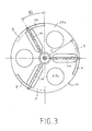
- La Figure 3 est une vue selon le plan III-III de la Figure 2,
- La Figure 4 est une vue d'un détail de la Figure 2, à échelle agrandie, illustrant l'alimentation radio-fréquence d'une antenne demi-onde dipole,
- La Figure 5 est un schéma électrique équivalent illustrant le principe de l'alimentation radio-électrique de l'antenne conforme à l'invention, et
- Les Figures 6 à 10 représentent une antenne conforme à l'invention selon diverses variantes de réalisation.
- Le dimensionnement des éléments constitutifs de l'antenne représentée aux dessins annexés, peut être facilement déterminé à partir des valeurs des paramètres exprimées dans la description ci-après, en fonction de la longueur d'onde de travail X. dans l'air. Dans le cas où, pour des raisons de tenue mécanique, les éléments d'antenne sont noyés dans un milieu électriquement isolant de constante diélectrique relative Er, il y aura lieu d'appliquer un coefficient de raccourcissement K (qui dépend en particulier de Er).
- A la Figure 1, les éléments repérés 1, 2, 3 et 4 forment l'ensemble rayonnant supérieur, en polarisation rectiligne verticale, du type antenne à manchette. Ces éléments sont coaxiaux.
- Les éléments 1, 2, 3 et 4 sont métalliques et soudés entre eux pour établir une continuité radio-électrique, l'élément 2 étant un élément coaxial d'alimentation en énergie qui est recouvert par un matériau électriquement isolant de nature appropriée 26.
- Les paires respectives d'éléments électriquement conducteurs (par exemple réalisés en cuivre) 5 et 6, 7 et 8 et 9 et 10, conformés en arc de cercle ou section de tore, forment trois antennes demi-onde en polarisation rectiligne horizontale alimentées en leur centre par des éléments de symétrisation de courant respectivement repérés 11, 12 et 13. Les paires d'éléments rayonnants précités sont solidarisées à la périphérie d'un plateau support 25 en matériau électriquement isolant (par exemple en résine époxyde) et coaxial à l'élément d'antenne à manchette précité, et sont régulièrement angulairement disposées à la périphérie de ce plateau. Chaque paire d'éléments rayonnants précitée 5 à 10 comprend un élément disposé sur la face supérieure 25a du plateau 25 et un élément disposé contre la face inférieure 25b du plateau 25, les deux éléments d'une même paire étant électriquement reliés par un cavalier conducteur tel que celui repéré 17 à la Figure 2. Le plateau 25 comprend également trois découpes circulaires 25c régulièrement angulairement espacées, chaque découpe circulaire 25c s'étendant entre deux éléments de symétrisation radiaux adjacents.
- En variante, les éléments 5 à 10, de préférence sous forme de conducteurs pleins, peuvent se présenter sous forme de segments de droite (voir Figure 6). Les éléments d'antenne à polarisation horizontale peuvent aussi n'être qu'au nombre de 2 et disposés comme schématiquement représentés aux Figures 7 et 8.
- Pour une antenne de petites dimensions, le plateau 25 n'est pas indispensable et l'antenne sera alors autoporteuse.
- La forme de réalisation représentée à la Figure 1 correspond à une antenne à polarisation circulaire droite. Par simple permutation circulaire des conducteurs respectivement 5 et 6, 7 et 8, 9 et 10, on obtient une antenne à polarisation circulaire gauche.
- Les découpes radiales oblongues 25d du plateau 25 logeant les éléments symétriseurs 11 à 13 permettent de ne pas modifier la "longueur électrique" desdits symétriseurs et d'éviter les aberrations de fonctionnement.
- Selon une autre variante de réalisation, les éléments d'antenne à polarisation horizontale A1 à A3 peuvent être réalisés sous forme d'un circuit imprimé.
- En outre, ainsi que représenté schématiquement à la Figure 9, chaque élément d'antenne A1 à A4 peut être réalisé sous forme d'élément plan connu de l'homme du métier.
- L'élément métallique repéré 16 (voir Figure 1), coaxial au plateau 25 et à l'antenne à manchette repérée A4 à la Figure 1 (les éléments rayonnants en polarisation rectiligne horizontale étant respectivement repérés A1, A2 et A3), forme l'armature extérieure des circuits d'alimentation des quatre éléments d'antenne précités et est prolongé, du côté opposé à l'élément d'antenne A4, par un organe support métallique 14, également coaxial au plateau 25, et par un connecteur coaxial d'extrémité 15 qui peut également être utilisé comme support d'une enveloppe 40 (représentée partiellement en trait mixte à la Figure 1) logeant l'antenne et de préférence remplie d'une mousse de polyuréthanne, ou d'un plan réflecteur métallique 41 représenté en trait mixte à la Figure 2. En variante, la mousse polyuréthanne précitée pourrait être remplacée par un matériau diélectrique ou magnétique permettant de réduire les dimensions physiques des éléments d'antenne.
- Les découpes 25c permettent ainsi un bon remplissage de l'enveloppe 40 malgré la présence du plateau 25.
- Sensiblement en regard du plateau 25, l'antenne conforme à l'invention comprend également, coaxiale à celui-ci, la tête intérieure 22 du transformateur d'impédance qui reçoit les âmes coaxiales d'alimentation radio-fréquence (RF) de l'antenne en polarisation verticale A4, c'est-à-dire l'âme coaxiale repérée 20, et des trois antennes A1 à A3 en polarisation horizontale, c'est-à-dire les âmes coaxiales repérées 19 qui s'étendent, en regard de la tête 22 précitée, perpendiculairement à l'âme coaxiale 20 de l'antenne A4.
- La tête 22 dudit transformateur d'impédance est prolongée vers le bas par un élément cylindrique métallique 23 qui constitue la section de transformation de l'antenne selon l'invention et qui est maintenu en place à l'intérieur d'un manchon cylindrique isolant 24 également coaxial au plateau 25, en particulier.
- Le conducteur 23 est prolongé vers le bas, c'est-à-dire vers le connecteur coaxial 15, par un élément cylindrique métallique 18 qui constitue la ligne d'alimentation coaxiale 50 ohms de l'antenne.
- Selon une variante de réalisation, les éléments symétriseurs 11 à 13 peuvent être interconnectés au point 2 de sorte que la tête d'impédance 22 se trouve ramenée en ce point 2.
- A l'exclusion des éléments repérés respectivement 24 à 27 qui sont réalisés en matériau électriquement isolant, de nature appropriée (téflon, polyéthylène ou céramique), tous les autres éléments constitutifs de l'antenne sont réalisés en matériau conducteur des courants radio-fréquence et interconnectés entre eux de manière que, si l'antenne est alimentée en courant continu, tous les points de la structure métallique de cette antenne soient au même potentiel.
- Les éléments radiaux de symétrisation repérés 11 et 11' (voir Figures 2 et 4) ou 11, 12 et 13 (voir Figure 1) forment avec les cavaliers d'interconnexion repérés 17 (voir Figures 1, 2 et 4) et les manchons isolants 27 entourant les conducteurs de symétrisation précités (voir Figure 4), des symétriseurs du type "trombone" qui permettent l'alimentation radio-fréquence des éléments rayonnants en polarisation horizontale respectivement 5, 6; 7, 8 et 9, 10.
- Les Figures 4 et 5 représentent le principe de l'alimentation radio-électrique de l'antenne. La Figure 4 illustre en particulier le détail de l'alimentation radio-fréquence des éléments rayonnants en polarisation horizonta le avec l'utilisation d'un symétriseur du type trombone connu en lui-même. Il peut bien entendu être utilisé tout autre type de symétriseur (par exemple du type bazooka).
- Les potentiels Vo et les phases 4)D (voir Figure 4) doivent être identiques en 17 pour chacune des antennes en polarisation horizontale. De plus, il est nécessaire que la phase en 2 soit identique à la phase 4)D et que l'amplitude en ce point soit très peu différente.
- Les antennes en polarisation horizontale sont placées sur un cercle de rayon

R , expression dans laquelle n est impair et vaut 1, 3, 5 etc... et r = 1 pour l'air. - L'antenne en polarisation verticale est dimensionnée pour être accordée à la fréquence de travail selon les calculs classiques liés aux antennes et connus de l'homme du métier. Il en est de même pour les éléments rayonnants en polarisation horizontale qui sont accordés à la fréquence de travail.
- L'antenne conforme à l'invention peut fonctionner dans une bande de fréquence relativement importante (environ 20%) si on dimensionne les éléments rayonnant en conséquence. A cet effet, les trajets coaxiaux repérés 21, 11 et 11' (voir Figure 2) doivent avoir une "longueur électrique" identique de sorte que les phases φd en 2 et 17 soient elles aussi identiques.
- La répartition des impédances aux points repérés 20 et 22 (Figure 2) est telle que l'amplitude et la phase du champ radio-électrique produit dans une direction de l'espace par l'élément en polarisation verticale A4 (direction parallèle à cet élément) et l'amplitude et la phase du champ produit en 17 par les éléments en polarisation horizontale A1 à A3 soient identiques.
- Le transformateur 21 permet d'obtenir les résultats précités et le transformateur 23 permet de ramener l'impédance de l'antenne conforme à l'invention à 50 ohms.
- Un prototype d'antenne selon l'invention a été réalisé par le déposant, à l'aide de dipoles demie-onde dans une bande de fréquence comprise entre 2,3 et 2,6 GHz. Dans ce cas, le gain mesuré par rapport à l'isotrope circulaire est égal à 4 dB dans la bande de fréquence précitée et le taux d'elliptici- té à 90° de l'axe longitudinal, inférieur à 1 dB. Le ROS (rapport d'onde stationnaire) dans la bande précitée est inférieur à 1,6 par rapport à 50 ohms. La couverture azimut est omnidirective à ± 0,5 dB et la couverture site varie dans la bande 2,3-2,6 GHz de 60 à 70° d'ouverture à 1/2 puissance. Dans ce cas également, le maximum d'énergie est dirigé sur l'horizon.
- L'élément rayonnant en polarisation verticale A4 10 est calculé comme un dipole à manchette demie-onde classique. Les dimensions Il et 12 (voir Figure 2) sont fonction du rapport I/a (longueur sur diamètre) sachant que Il + 12 est toujours légèrement inférieur à o ( λo: longueur d'onde de travail).
- Le diamètre des éléments rayonnants 5, 6; 7, 8 et 9, 10 des trois antennes demie-onde A1 à A3 en polarisation horizontale joue également sur la longueur des demi-éléments r x θi i voir Figure 3) et dans ce cas, on obtient rx θi légèrement inférieur à o.
- Le diamètre 24 x r de disposition des trois éléments rayonnants demie-onde à polarisation horizontale est égal à2 o dans l'air et à o x(∈r)-1 dans un milieu de permitivité relative r.
- Pour un fonctionnement optimal de l'antenne, il est recommandé que le diamètre de l'élément rayonnant à polarisation verticale soit inférieur à # o.
- Pour que chacune des antennes soit alimentée par des courants de même amplitude et de même phase, la longueur des éléments coaxiaux d'alimentation repérés 4 pour l'élément d'antenne A4 et 11, 12, 13 pour les trois éléments d'antenne horizontaux doivent être rigoureusement identiques c'est-à-dire I1 = 12 = I3 = 14.
- Une application particulièrement intéRessante de l'antenne conforme à l'invention, que l'on peut qualifier d'antenne omnididirective à polarisation circulaire transversale et à maximum de gain sous l'horizon, se situe dans le domaine des transmissions tout azimut sol-sol, sol-air, sol-mer, air-sol, air-mer, air-air, mer-sol, mer-air, mer-mer, en milieu environnant perturbé. L'utilisation d'une antenne en polarisation circulaire pour de telles transmissions qui impliquent une énergie maximale sous l'horizon, permet de limiter considérablement la gêne apportée par l'environnement perturbateur, puisqu'en cas de réflexion sur un obstacle métallique proche, il y a inversion de la polarisation de l'onde réfléchie.
- La variante de réalisation représentée à la Figure 10 est également possible. Dans ce cas, chaque dipole à polarisation horizontale (un seul est représenté Figure 10) est supporté axialement par deux éléments symétriseurs verticaux, par rapport à un plateau réflecteur de base commun 41.
- On notera que les centres de phase des éléments d'antenne à polarisation horizontale se situent aux points repérés 17 tandis que le centre de phase de l'élément à polarisation verticale se situe au point 2.
- Une autre application particulièrement intéressante de l'antenne conforme à l'invention, est la réalisation d'un émetteur FM de puissance réduite.
- Les signes de référence insérés après les caractéristiques techniques mentionnées dans les revendications, ont pour seul but de faciliter la compréhension de ces dernières, et n'en limitent aucunement la portée.
Claims (12)
Applications Claiming Priority (1)
| Application Number | Priority Date | Filing Date | Title |
|---|---|---|---|
| FR8903778A FR2644937B1 (fr) | 1989-03-22 | 1989-03-22 | Antenne omnidirective en polarisation circulaire transversale a maximum de gain sous l'horizon |
Publications (2)
| Publication Number | Publication Date |
|---|---|
| EP0463263A1 true EP0463263A1 (fr) | 1992-01-02 |
| EP0463263B1 EP0463263B1 (fr) | 1994-04-13 |
Family
ID=9379964
Family Applications (1)
| Application Number | Title | Priority Date | Filing Date |
|---|---|---|---|
| EP19900401787 Expired - Lifetime EP0463263B1 (fr) | 1989-03-22 | 1990-06-22 | Antenne omnidirective en polarisation circulaire transversale à maximum de gain sous l'horizon |
Country Status (5)
| Country | Link |
|---|---|
| EP (1) | EP0463263B1 (fr) |
| DE (1) | DE69008170T2 (fr) |
| DK (1) | DK0463263T3 (fr) |
| ES (1) | ES2053136T3 (fr) |
| FR (1) | FR2644937B1 (fr) |
Cited By (4)
| Publication number | Priority date | Publication date | Assignee | Title |
|---|---|---|---|---|
| FR2721757A1 (fr) * | 1994-06-28 | 1995-12-29 | Jac International | Antenne omnidirectionnelle en azimut et directive en site et répondeur maritime ainsi équipé. |
| US7411399B2 (en) * | 2005-10-04 | 2008-08-12 | Schlumberger Technology Corporation | Electromagnetic survey system with multiple sources |
| CN103822973A (zh) * | 2014-02-26 | 2014-05-28 | 北京工业大学 | 一种全向性的水平剪切模态磁致伸缩传感器 |
| CN109216941A (zh) * | 2018-09-03 | 2019-01-15 | 吴通控股集团股份有限公司 | 一种小型干涉仪测向天线组 |
Families Citing this family (7)
| Publication number | Priority date | Publication date | Assignee | Title |
|---|---|---|---|---|
| FR2676311B1 (fr) * | 1991-05-07 | 1993-11-19 | Agence Spatiale Europeenne | Antenne a polarisation circulaire. |
| GB2259811B (en) * | 1991-09-21 | 1995-05-17 | Motorola Israel Ltd | An antenna |
| RU2169418C2 (ru) * | 1999-06-22 | 2001-06-20 | Российский Федеральный Ядерный Центр - Всероссийский Научно-Исследовательский Институт Экспериментальной Физики | Антенна эллиптической поляризации |
| US8803749B2 (en) | 2011-03-25 | 2014-08-12 | Kwok Wa Leung | Elliptically or circularly polarized dielectric block antenna |
| GB2512111B (en) | 2013-03-20 | 2017-02-15 | British Broadcasting Corp | Antenna arrangement for transmitting two or more polarisations of radio signal |
| US9899746B2 (en) * | 2013-12-14 | 2018-02-20 | The Charles Stark Draper Laboratory, Inc. | Electronically steerable single helix/spiral antenna |
| FR3060089B1 (fr) | 2016-12-08 | 2019-08-23 | Mbda France | Ensemble d'equilibrage a bagues d'equilibrage pour missile et missile pourvu d'un tel ensemble d'equilibrage |
Citations (6)
| Publication number | Priority date | Publication date | Assignee | Title |
|---|---|---|---|---|
| US2217911A (en) * | 1938-08-12 | 1940-10-15 | Rca Corp | Radio communication |
| US2532428A (en) * | 1946-11-14 | 1950-12-05 | United Broadeasting Company | Elliptical polarization electromagnetic energy radiation system |
| US3348228A (en) * | 1965-08-02 | 1967-10-17 | Raytheon Co | Circular dipole antenna array |
| US3555552A (en) * | 1969-12-19 | 1971-01-12 | Andrew Alford | Dual polarized antenna system with controlled field pattern |
| US4083051A (en) * | 1976-07-02 | 1978-04-04 | Rca Corporation | Circularly-polarized antenna system using tilted dipoles |
| US4555708A (en) * | 1984-01-10 | 1985-11-26 | The United States Of America As Represented By The Secretary Of The Air Force | Dipole ring array antenna for circularly polarized pattern |
-
1989
- 1989-03-22 FR FR8903778A patent/FR2644937B1/fr not_active Expired - Lifetime
-
1990
- 1990-06-22 DK DK90401787T patent/DK0463263T3/da active
- 1990-06-22 EP EP19900401787 patent/EP0463263B1/fr not_active Expired - Lifetime
- 1990-06-22 DE DE1990608170 patent/DE69008170T2/de not_active Expired - Fee Related
- 1990-06-22 ES ES90401787T patent/ES2053136T3/es not_active Expired - Lifetime
Patent Citations (6)
| Publication number | Priority date | Publication date | Assignee | Title |
|---|---|---|---|---|
| US2217911A (en) * | 1938-08-12 | 1940-10-15 | Rca Corp | Radio communication |
| US2532428A (en) * | 1946-11-14 | 1950-12-05 | United Broadeasting Company | Elliptical polarization electromagnetic energy radiation system |
| US3348228A (en) * | 1965-08-02 | 1967-10-17 | Raytheon Co | Circular dipole antenna array |
| US3555552A (en) * | 1969-12-19 | 1971-01-12 | Andrew Alford | Dual polarized antenna system with controlled field pattern |
| US4083051A (en) * | 1976-07-02 | 1978-04-04 | Rca Corporation | Circularly-polarized antenna system using tilted dipoles |
| US4555708A (en) * | 1984-01-10 | 1985-11-26 | The United States Of America As Represented By The Secretary Of The Air Force | Dipole ring array antenna for circularly polarized pattern |
Non-Patent Citations (1)
| Title |
|---|
| PATENT ABSTRACTS OF JAPAN vol. 7, no. 258 (E-211)(1403), 17 novembre 1983; & JP - A - 58142605 (NIPPON DENSHIN DENWA KOSHA) 24.08.1983 * |
Cited By (5)
| Publication number | Priority date | Publication date | Assignee | Title |
|---|---|---|---|---|
| FR2721757A1 (fr) * | 1994-06-28 | 1995-12-29 | Jac International | Antenne omnidirectionnelle en azimut et directive en site et répondeur maritime ainsi équipé. |
| US7411399B2 (en) * | 2005-10-04 | 2008-08-12 | Schlumberger Technology Corporation | Electromagnetic survey system with multiple sources |
| US7642784B2 (en) * | 2005-10-04 | 2010-01-05 | Westerngeco L.L.C. | Electromagnetic survey system with multiple sources |
| CN103822973A (zh) * | 2014-02-26 | 2014-05-28 | 北京工业大学 | 一种全向性的水平剪切模态磁致伸缩传感器 |
| CN109216941A (zh) * | 2018-09-03 | 2019-01-15 | 吴通控股集团股份有限公司 | 一种小型干涉仪测向天线组 |
Also Published As
| Publication number | Publication date |
|---|---|
| DK0463263T3 (da) | 1994-06-06 |
| FR2644937A1 (fr) | 1990-09-28 |
| EP0463263B1 (fr) | 1994-04-13 |
| FR2644937B1 (fr) | 1991-09-27 |
| ES2053136T3 (es) | 1994-07-16 |
| DE69008170T2 (de) | 1994-10-13 |
| DE69008170D1 (de) | 1994-05-19 |
Similar Documents
| Publication | Publication Date | Title |
|---|---|---|
| EP0427654B1 (fr) | Antenne en hélice, quadrifilaire, résonnante bicouche | |
| EP0243289B1 (fr) | Antenne plaque à double polarisations croisées | |
| Nakano et al. | A monofilar spiral antenna and its array above a ground plane-formation of a circularly polarized tilted fan beam | |
| FR2752646A1 (fr) | Antenne imprimee plane a elements superposes court-circuites | |
| EP1073143B1 (fr) | Antenne imprimée bi-polarisation et réseau d'antennes correspondant | |
| EP1407512B1 (fr) | Antenne | |
| CA1290449C (fr) | Dispositif d'excitation d'un guide d'onde en polarisation circulaire par une antenne plane | |
| US20030085845A1 (en) | Collinear coaxial slot-fed-biconical array antenna | |
| CA2019181A1 (fr) | Element rayonnant diplexant | |
| FR2810163A1 (fr) | Perfectionnement aux antennes-sources d'emission/reception d'ondes electromagnetiques | |
| FR2640431A1 (fr) | Dispositif rayonnant multifrequence | |
| JPS6125304A (ja) | 小型適応型アレイアンテナ | |
| FR2907602A1 (fr) | Antenne a fils multiples a double polarisation. | |
| EP0463263B1 (fr) | Antenne omnidirective en polarisation circulaire transversale à maximum de gain sous l'horizon | |
| EP0327965A2 (fr) | Antenne multifréquence, utilisable notamment dans le domaine des télécommunications spatiales | |
| FR2746547A1 (fr) | Antenne helice a alimentation large bande integree, et procedes de fabrication correspondants | |
| EP1225655A1 (fr) | Antenne planaire et dispositif de transmission bi-bande incluant cette antenne | |
| FR2578105A1 (fr) | Antenne plane a micro-ondes | |
| EP1516392B1 (fr) | Antenne a brins | |
| EP1550183A2 (fr) | Element rayonnant large bande a double polarisation, de forme generale carree | |
| CA2006291C (fr) | Dispositif rayonnant bifrequence | |
| EP0020196B1 (fr) | Antenne réseau hyperfréquence du type disque avec son dispositif d'alimentation, et application aux radars d'écartométrie | |
| EP0477102B1 (fr) | Réseau directif pour radiocommunications, à éléments rayonnants adjacents et ensemble de tels réseaux directifs | |
| FR2664749A1 (fr) | Antenne microonde. | |
| EP4572015A1 (fr) | Antenne réseau améliorée du type comportant une pluralité d'éléments rayonnants planaires alimentés en série |
Legal Events
| Date | Code | Title | Description |
|---|---|---|---|
| PUAI | Public reference made under article 153(3) epc to a published international application that has entered the european phase |
Free format text: ORIGINAL CODE: 0009012 |
|
| 17P | Request for examination filed |
Effective date: 19910704 |
|
| AK | Designated contracting states |
Kind code of ref document: A1 Designated state(s): BE CH DE DK ES GB IT LI NL SE |
|
| 17Q | First examination report despatched |
Effective date: 19930714 |
|
| GRAA | (expected) grant |
Free format text: ORIGINAL CODE: 0009210 |
|
| RAP1 | Party data changed (applicant data changed or rights of an application transferred) |
Owner name: ETABLISSEMENTS DAVEY BICKFORD SMITH & CIE |
|
| AK | Designated contracting states |
Kind code of ref document: B1 Designated state(s): BE CH DE DK ES GB IT LI NL SE |
|
| REF | Corresponds to: |
Ref document number: 69008170 Country of ref document: DE Date of ref document: 19940519 |
|
| GBT | Gb: translation of ep patent filed (gb section 77(6)(a)/1977) |
Effective date: 19940503 |
|
| REG | Reference to a national code |
Ref country code: DK Ref legal event code: T3 |
|
| ITF | It: translation for a ep patent filed | ||
| REG | Reference to a national code |
Ref country code: ES Ref legal event code: FG2A Ref document number: 2053136 Country of ref document: ES Kind code of ref document: T3 |
|
| EAL | Se: european patent in force in sweden |
Ref document number: 90401787.8 |
|
| PLBE | No opposition filed within time limit |
Free format text: ORIGINAL CODE: 0009261 |
|
| 26N | No opposition filed | ||
| PGFP | Annual fee paid to national office [announced via postgrant information from national office to epo] |
Ref country code: NL Payment date: 19990603 Year of fee payment: 10 |
|
| PGFP | Annual fee paid to national office [announced via postgrant information from national office to epo] |
Ref country code: SE Payment date: 19990616 Year of fee payment: 10 Ref country code: GB Payment date: 19990616 Year of fee payment: 10 |
|
| PGFP | Annual fee paid to national office [announced via postgrant information from national office to epo] |
Ref country code: DK Payment date: 19990628 Year of fee payment: 10 |
|
| PGFP | Annual fee paid to national office [announced via postgrant information from national office to epo] |
Ref country code: ES Payment date: 19990629 Year of fee payment: 10 |
|
| PGFP | Annual fee paid to national office [announced via postgrant information from national office to epo] |
Ref country code: DE Payment date: 19990702 Year of fee payment: 10 |
|
| PGFP | Annual fee paid to national office [announced via postgrant information from national office to epo] |
Ref country code: BE Payment date: 19990715 Year of fee payment: 10 |
|
| PGFP | Annual fee paid to national office [announced via postgrant information from national office to epo] |
Ref country code: CH Payment date: 19990914 Year of fee payment: 10 |
|
| PG25 | Lapsed in a contracting state [announced via postgrant information from national office to epo] |
Ref country code: GB Free format text: LAPSE BECAUSE OF NON-PAYMENT OF DUE FEES Effective date: 20000622 Ref country code: DK Free format text: LAPSE BECAUSE OF NON-PAYMENT OF DUE FEES Effective date: 20000622 |
|
| PG25 | Lapsed in a contracting state [announced via postgrant information from national office to epo] |
Ref country code: SE Free format text: LAPSE BECAUSE OF NON-PAYMENT OF DUE FEES Effective date: 20000623 Ref country code: ES Free format text: THE PATENT HAS BEEN ANNULLED BY A DECISION OF A NATIONAL AUTHORITY Effective date: 20000623 |
|
| PG25 | Lapsed in a contracting state [announced via postgrant information from national office to epo] |
Ref country code: LI Free format text: LAPSE BECAUSE OF NON-PAYMENT OF DUE FEES Effective date: 20000630 Ref country code: CH Free format text: LAPSE BECAUSE OF NON-PAYMENT OF DUE FEES Effective date: 20000630 Ref country code: BE Free format text: LAPSE BECAUSE OF NON-PAYMENT OF DUE FEES Effective date: 20000630 |
|
| BERE | Be: lapsed |
Owner name: ETS DAVEY BICKFORD SMITH & CIE Effective date: 20000630 |
|
| PG25 | Lapsed in a contracting state [announced via postgrant information from national office to epo] |
Ref country code: NL Free format text: LAPSE BECAUSE OF NON-PAYMENT OF DUE FEES Effective date: 20010101 |
|
| GBPC | Gb: european patent ceased through non-payment of renewal fee |
Effective date: 20000622 |
|
| REG | Reference to a national code |
Ref country code: CH Ref legal event code: PL |
|
| EUG | Se: european patent has lapsed |
Ref document number: 90401787.8 |
|
| REG | Reference to a national code |
Ref country code: DK Ref legal event code: EBP |
|
| NLV4 | Nl: lapsed or anulled due to non-payment of the annual fee |
Effective date: 20010101 |
|
| PG25 | Lapsed in a contracting state [announced via postgrant information from national office to epo] |
Ref country code: DE Free format text: LAPSE BECAUSE OF NON-PAYMENT OF DUE FEES Effective date: 20010403 |
|
| REG | Reference to a national code |
Ref country code: ES Ref legal event code: FD2A Effective date: 20020204 |
|
| PG25 | Lapsed in a contracting state [announced via postgrant information from national office to epo] |
Ref country code: IT Free format text: LAPSE BECAUSE OF NON-PAYMENT OF DUE FEES;WARNING: LAPSES OF ITALIAN PATENTS WITH EFFECTIVE DATE BEFORE 2007 MAY HAVE OCCURRED AT ANY TIME BEFORE 2007. THE CORRECT EFFECTIVE DATE MAY BE DIFFERENT FROM THE ONE RECORDED. Effective date: 20050622 |