EP0463300A2 - Lagerung der Kassettenfachklappe eines Video-Gerätes - Google Patents
Lagerung der Kassettenfachklappe eines Video-Gerätes Download PDFInfo
- Publication number
- EP0463300A2 EP0463300A2 EP91105366A EP91105366A EP0463300A2 EP 0463300 A2 EP0463300 A2 EP 0463300A2 EP 91105366 A EP91105366 A EP 91105366A EP 91105366 A EP91105366 A EP 91105366A EP 0463300 A2 EP0463300 A2 EP 0463300A2
- Authority
- EP
- European Patent Office
- Prior art keywords
- bearing
- housing
- flap
- torsion spring
- lid
- Prior art date
- Legal status (The legal status is an assumption and is not a legal conclusion. Google has not performed a legal analysis and makes no representation as to the accuracy of the status listed.)
- Granted
Links
Images
Classifications
-
- G—PHYSICS
- G11—INFORMATION STORAGE
- G11B—INFORMATION STORAGE BASED ON RELATIVE MOVEMENT BETWEEN RECORD CARRIER AND TRANSDUCER
- G11B33/00—Constructional parts, details or accessories not provided for in the other groups of this subclass
- G11B33/02—Cabinets; Cases; Stands; Disposition of apparatus therein or thereon
- G11B33/027—Covers
-
- G—PHYSICS
- G11—INFORMATION STORAGE
- G11B—INFORMATION STORAGE BASED ON RELATIVE MOVEMENT BETWEEN RECORD CARRIER AND TRANSDUCER
- G11B15/00—Driving, starting or stopping record carriers of filamentary or web form; Driving both such record carriers and heads; Guiding such record carriers or containers therefor; Control thereof; Control of operating function
- G11B15/675—Guiding containers, e.g. loading, ejecting cassettes
Definitions
- the invention relates to the mounting of a movable flap, in particular a cassette compartment flap of a video device according to the preamble of claim 1.
- This type of storage has the disadvantage that the biasing of the torsion spring can usually only take place in the assembled state of the bearing parts, which can often only take place with considerable disability, often due to the tight spatial conditions. The result is an increase in the price of the assembly process.
- the invention has for its object to avoid the disadvantage mentioned, and thus to create a simpler and cheaper installation option.
- the torsion spring is preloaded before the flap is installed in the housing.
- the bearing point of the torsion spring is still easily accessible, so preloading is relatively easy.
- the torsion spring is biased by an amount slightly above that which the torsion spring must have in its working area.
- the spring leg lying on the outer boundary of the bearing side is preloaded by the necessary amount and placed behind a flap-side projection, whereby the preload is retained.
- the force emanating from the preloaded torsion spring is therefore closed inside the flap and cannot act outwards.
- the flap is still a forcefully passive part and can be used as such can be easily installed in the housing.
- the bearing journal (7) is molded onto the flap (2) and forms the radial bearing together with the housing-side parts (10, 13) and the axial bearing with (10, 10 ').
- An extension (3) of the bearing pin (7) for The outside of the flap carries the torsion spring (1). 1 and 2, the prestressed spring leg (4) is shown under the flap-side projection (6) and in the partially relaxed state in the depression (9).
- the flap (2) with the prestressed torsion spring (1) is installed in the housing (5) in the open position of the flap (2) (Fig. 2). If this is then inserted into its bearing points and is brought into its closed position, the conical rib (8) on the housing side causes the spring leg (4) to be pushed out from under the projection (6) and relaxes until it contacts the housing (5).
Landscapes
- Fittings On The Vehicle Exterior For Carrying Loads, And Devices For Holding Or Mounting Articles (AREA)
- Packaging Of Annular Or Rod-Shaped Articles, Wearing Apparel, Cassettes, Or The Like (AREA)
- Closing And Opening Devices For Wings, And Checks For Wings (AREA)
- Closures For Containers (AREA)
- Vehicle Step Arrangements And Article Storage (AREA)
- Automatic Tape Cassette Changers (AREA)
- Feeding And Guiding Record Carriers (AREA)
Abstract
Description
- Die Erfindung betrifft die Lagerung einer beweglichen Klappe, insbesondere Kassettenfachklappe eines Video-Gerätes gemäß dem Oberbegriff des Anspruchs 1.
- Es ist bekannt, Lagerungen von beweglichen Teilen, Klappen oder dergleichen durch am beweglichen Teil angespritzte Lagerzapfen auszuführen, die zusammen mit einem Lagerbett die Drehlagerung bilden. Bekannt ist ebenfalls, zum Andrücken des beweglichen Teils an einen Anschlag in der Ruhelage des Teils, eine Drehfeder zu verwenden. Diese Drehfeder muß in einem gespannten Zustand so angeordnet sein, daß der eine Federschenkel an dem beweglichen Teil und der andere Federschenkel an dem ruhenden, das Lagerbett beinhaltenden Teil anliegt.
- Diese Art der Lagerung hat den Nachteil, daß das Vorspannen der Drehfeder meist erst im montierten Zustand der Lagerteile erfolgen kann, was oft, oftmals bedingt durch enge räumliche Verhältnisse, nur unter erheblicher Behinderung erfolgen kann. Die Folge ist eine Verteuerung des Montagevorgangs.
- Der Erfindung liegt die Aufgabe zugrunde, den genannten Nachteil zu vermeiden, und damit eine einfachere und billigere Montagemöglichkeit zu schaffen.
- Diese Aufgabe wird durch die im Anspruch 1 gekennzeichneten Merkmale gelöst.
- Das Vorspannen der Drehfeder erfolgt bereits vor der Montage der Klappe in das Gehäuse. Die Lagerstelle der Drehfeder ist dabei noch leicht zugänglich, das Vorspannen also relativ einfach. Die Drehfeder wird dabei um einen Betrag vorgespannt der etwas über dem liegt, den die Drehfeder in ihrem Arbeitsbereich haben muß. Der an der äußeren Begrenzung der Lagerseite liegende Federschenkel wird um den notwendigen Betrag vorgespannt und hinter einen klappenseitigen Vorsprung gelegt, wodurch die Vorspannung erhalten bleibt. Die von der vorgespannten Drehfeder ausgehende Kraft ist also innerhalb der Klappe geschlossen und kann nicht nach außen wirken. Die Klappe ist damit nach wie vor ein kräftemäßig passives Teil und kann als solches problemlos in das Gehäuse montiert werden. Erst wenn die Klappe mit ihren Lagerbolzen im Lagerbett des Gehäuses liegt und innerhalb ihres Schwenkbereichs bewegt wird, bewirkt eine gehäuseseitige konische Rippe, daß der vorgespannte Federschenkel unter dem klappenseitigen Vorsprung hervorgeschoben wird und sich in entspannender Richtung soweit bewegt, bis er an seinem gehäuseseitigen Anschlag zur Anlage kommt. Die noch vorhandene Restspannung in der Drehfeder reicht aus, um das notwendige Klappenrückstell-Drehmoment aufzubringen.
- Die Erfindung wird nachstehend anhand der in den Zeichnungen dargestellten Ausführungsform erläutert.
- Fig. 1
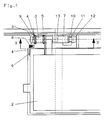
- zeigt eine Teilansicht auf eine Klappe mit ihrer Lagerung im Gehäuse, wobei sich auf der nicht gezeichneten Klappenseite eine gleiche oder ähnliche Lagerung wie gezeichnet befindet.
- Fig. 2
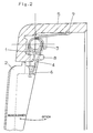
- zeigt einen Schnitt durch den die Drehfeder tragenden Bereich der Lagerung senkrecht zur Lagerachse.
- Fig. 3
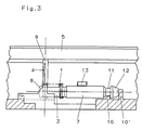
- zeigt die Lagerung im Schnitt X-X der Figur 1.
- An die Klappe (2) ist der Lagerzapfen (7) angespritzt, der zusammen mit den gehäuseseitigen Teilen (10, 13) die radiale und mit (10, 10') die axiale Lagerung bildet. Eine Verlängerung (3) des Lagerzapfens (7) zur Klappenaußenseite zu trägt die Drehfeder (1). In Fig. 1 und 2 ist der vorgespannte Federschenkel (4) unter dem klappenseitigen Vorsprung (6) liegend und im teilweise entspannten Zustand in der Vertiefung (9) dargestellt. Die Montage der Klappe (2) mit der vorgespannten Drehfeder (1) in das Gehäuse (5) erfolgt in der offenen Stellung der Klappe (2) (Fig. 2). Ist diese dann in ihre Lagerstellen eingeschoben und wird in ihre geschlossene Stellung gebracht, bewirkt die gehäuseseitige konische Rippe (8), daß der Federschenkel (4) unter dem Vorsprung (6) hervorgeschoben wird und sich bis zur Anlage am Gehäuse (5) entspannt.
Claims (5)
- Lagerung der Kassettenfachklappe eines Videogerätes, bestehend aus Lagerzapfen, Lagerbett und Drehfeder, dadurch gekennzeichnet, daß die vorgespannte Drehfeder (1) auf einer Verlängerung (3) des Lagerzapfens (7) gelagert ist, ein Federschenkel an der beweglichen Klappe (2) und der zweite vorgespannte Federschenkel (4) am Gehäuse (5) angreift, ein Vorsprung (6) an der Klappe (2), und eine gehäuseseitige konische Rippe (8) vorhanden ist.
- Lagerung nach Anspruch 1, dadurch gekennzeichnet, daß der Federschenkel (4) der Drehfeder (1) nach erfolgter Montage der Klappe in einer Vertiefung (9) des Gehäuses (5) liegt.
- Lagerung nach Anspruch 1, dadurch gekennzeichnet, daß die Verlängerung (3) des Lagerzapfens (7) an ihrem Ende eine Verdickung (3 ) aufweist.
- Lagerung nach Anspruch 1 , dadurch gekennzeichnet, daß der Lagerzapfen (7) einen Bereich (11) geringeren Durchmessers aufweist, der auf einer Lagerrippe (10) des Gehäuses (5) aufliegt und daß zusammen mit dem Lagersteg (13) die radiale Lagerung gebildet wird.
- Lagerung nach Anspruch 1, dadurch gekennzeichnet, daß die pilzartige Verdickung (12) des Lagerzapfens (7) zusammen mit den Lagerrippen (10, 10') die axiale Sicherung der Lagerung bildet.
Applications Claiming Priority (2)
| Application Number | Priority Date | Filing Date | Title |
|---|---|---|---|
| DE9006983U DE9006983U1 (de) | 1990-06-22 | 1990-06-22 | Lagerung der Kassettenfachklappe eines Video-Gerätes |
| DE9006983U | 1990-06-22 |
Publications (3)
| Publication Number | Publication Date |
|---|---|
| EP0463300A2 true EP0463300A2 (de) | 1992-01-02 |
| EP0463300A3 EP0463300A3 (en) | 1992-05-06 |
| EP0463300B1 EP0463300B1 (de) | 1995-11-15 |
Family
ID=6854845
Family Applications (1)
| Application Number | Title | Priority Date | Filing Date |
|---|---|---|---|
| EP91105366A Expired - Lifetime EP0463300B1 (de) | 1990-06-22 | 1991-04-04 | Lagerung der Kassettenfachklappe eines Video-Gerätes |
Country Status (3)
| Country | Link |
|---|---|
| EP (1) | EP0463300B1 (de) |
| AT (1) | ATE130458T1 (de) |
| DE (2) | DE9006983U1 (de) |
Cited By (1)
| Publication number | Priority date | Publication date | Assignee | Title |
|---|---|---|---|---|
| US10954010B2 (en) | 2013-04-03 | 2021-03-23 | Jt International S.A. | Packaging apparatus and method |
Family Cites Families (2)
| Publication number | Priority date | Publication date | Assignee | Title |
|---|---|---|---|---|
| US4795109A (en) * | 1985-12-23 | 1989-01-03 | Gold Star Co., Ltd. | Tape cassette loading device |
| JPS62295291A (ja) * | 1986-06-14 | 1987-12-22 | Alps Electric Co Ltd | ドア装置 |
-
1990
- 1990-06-22 DE DE9006983U patent/DE9006983U1/de not_active Expired - Lifetime
-
1991
- 1991-04-04 EP EP91105366A patent/EP0463300B1/de not_active Expired - Lifetime
- 1991-04-04 AT AT91105366T patent/ATE130458T1/de not_active IP Right Cessation
- 1991-04-04 DE DE59106891T patent/DE59106891D1/de not_active Expired - Fee Related
Cited By (1)
| Publication number | Priority date | Publication date | Assignee | Title |
|---|---|---|---|---|
| US10954010B2 (en) | 2013-04-03 | 2021-03-23 | Jt International S.A. | Packaging apparatus and method |
Also Published As
| Publication number | Publication date |
|---|---|
| ATE130458T1 (de) | 1995-12-15 |
| DE9006983U1 (de) | 1990-08-30 |
| EP0463300B1 (de) | 1995-11-15 |
| EP0463300A3 (en) | 1992-05-06 |
| DE59106891D1 (de) | 1995-12-21 |
Similar Documents
| Publication | Publication Date | Title |
|---|---|---|
| DE3742030C2 (de) | Schwenklager für Spannvorrichtungen | |
| DE69310146T2 (de) | Riemenspannvorreichtung | |
| EP2724059B1 (de) | Stellantrieb für ein kraftfahrzeug und verfahren | |
| DE69609533T2 (de) | Riemenspanner mit Dämpfung der Drehlagerbuchse | |
| DE19854945A1 (de) | Klemmrollenschaltwerk | |
| EP0415355A2 (de) | Schliessvorrichtung für ein Schloss, insbesondere Ringschloss | |
| DE2832160A1 (de) | Sicherheitsgurtaufroller | |
| DE1525103A1 (de) | Gestaengeverbindung,vorzugsweise fuer Scheibenwischergestaenge | |
| EP1131222B1 (de) | Verschluss für einen kraftstoffbehälter eines kraftfahrzeugs | |
| DE69315543T2 (de) | Anschlagpuffer für Zwischenlage zwischen relativ zueinander bewegbaren Karosserieteilen | |
| DE2435324A1 (de) | Laufrollenbeschlag | |
| DE102022108487A1 (de) | Abstandhaltervorrichtung | |
| DE3207922C1 (de) | Schwenklagerung für ein Türhalteband eines Türfeststellers für Kraftfahrzeugtüren | |
| DE69621080T2 (de) | Elastisches Lager für einen Fahrzeugmotor | |
| EP0463300B1 (de) | Lagerung der Kassettenfachklappe eines Video-Gerätes | |
| EP0968882B1 (de) | Klappdeckelverschluss | |
| DE102009013074B4 (de) | Anschlagpufferanordnung | |
| DE3729763A1 (de) | Bremsvorrichtung zum verhindern des zufallens einer geoeffneten fahrzeugtuer | |
| DE19717446A1 (de) | Anschlußeinrichtung | |
| DE10140211A1 (de) | Federsystem | |
| DE69303043T2 (de) | Fahrradfelgen-Bremsstütze | |
| DE4238679A1 (de) | Luftleiteinrichtung mit Staudruckklappe für Kraftfahrzeuge | |
| EP1361973A2 (de) | Hauptzylinder | |
| AT523278B1 (de) | Pyrotechnischer Aktuator | |
| DE69611673T2 (de) | Drosselklappensteuerungsvorrichtung |
Legal Events
| Date | Code | Title | Description |
|---|---|---|---|
| PUAI | Public reference made under article 153(3) epc to a published international application that has entered the european phase |
Free format text: ORIGINAL CODE: 0009012 |
|
| AK | Designated contracting states |
Kind code of ref document: A2 Designated state(s): AT DE FR GB IT |
|
| PUAL | Search report despatched |
Free format text: ORIGINAL CODE: 0009013 |
|
| AK | Designated contracting states |
Kind code of ref document: A3 Designated state(s): AT DE FR GB IT |
|
| 17P | Request for examination filed |
Effective date: 19921008 |
|
| 17Q | First examination report despatched |
Effective date: 19940804 |
|
| RAP1 | Party data changed (applicant data changed or rights of an application transferred) |
Owner name: GRUNDIG E.M.V. ELEKTRO-MECHANISCHE VERSUCHSANSTALT |
|
| GRAA | (expected) grant |
Free format text: ORIGINAL CODE: 0009210 |
|
| AK | Designated contracting states |
Kind code of ref document: B1 Designated state(s): AT DE FR GB IT |
|
| REF | Corresponds to: |
Ref document number: 130458 Country of ref document: AT Date of ref document: 19951215 Kind code of ref document: T |
|
| REF | Corresponds to: |
Ref document number: 59106891 Country of ref document: DE Date of ref document: 19951221 |
|
| ITF | It: translation for a ep patent filed | ||
| ET | Fr: translation filed | ||
| GBT | Gb: translation of ep patent filed (gb section 77(6)(a)/1977) |
Effective date: 19960201 |
|
| PLBE | No opposition filed within time limit |
Free format text: ORIGINAL CODE: 0009261 |
|
| STAA | Information on the status of an ep patent application or granted ep patent |
Free format text: STATUS: NO OPPOSITION FILED WITHIN TIME LIMIT |
|
| 26N | No opposition filed | ||
| REG | Reference to a national code |
Ref country code: FR Ref legal event code: TP |
|
| REG | Reference to a national code |
Ref country code: GB Ref legal event code: 746 Effective date: 20010322 |
|
| REG | Reference to a national code |
Ref country code: FR Ref legal event code: D6 |
|
| REG | Reference to a national code |
Ref country code: GB Ref legal event code: IF02 |
|
| REG | Reference to a national code |
Ref country code: GB Ref legal event code: 732E |
|
| REG | Reference to a national code |
Ref country code: FR Ref legal event code: TP |
|
| PGFP | Annual fee paid to national office [announced via postgrant information from national office to epo] |
Ref country code: GB Payment date: 20060410 Year of fee payment: 16 |
|
| PGFP | Annual fee paid to national office [announced via postgrant information from national office to epo] |
Ref country code: FR Payment date: 20060418 Year of fee payment: 16 |
|
| PGFP | Annual fee paid to national office [announced via postgrant information from national office to epo] |
Ref country code: AT Payment date: 20060424 Year of fee payment: 16 |
|
| PGFP | Annual fee paid to national office [announced via postgrant information from national office to epo] |
Ref country code: IT Payment date: 20060430 Year of fee payment: 16 |
|
| PGFP | Annual fee paid to national office [announced via postgrant information from national office to epo] |
Ref country code: DE Payment date: 20060508 Year of fee payment: 16 |
|
| GBPC | Gb: european patent ceased through non-payment of renewal fee |
Effective date: 20070404 |
|
| PG25 | Lapsed in a contracting state [announced via postgrant information from national office to epo] |
Ref country code: DE Free format text: LAPSE BECAUSE OF NON-PAYMENT OF DUE FEES Effective date: 20071101 |
|
| PG25 | Lapsed in a contracting state [announced via postgrant information from national office to epo] |
Ref country code: AT Free format text: LAPSE BECAUSE OF NON-PAYMENT OF DUE FEES Effective date: 20070404 |
|
| PG25 | Lapsed in a contracting state [announced via postgrant information from national office to epo] |
Ref country code: GB Free format text: LAPSE BECAUSE OF NON-PAYMENT OF DUE FEES Effective date: 20070404 |
|
| PG25 | Lapsed in a contracting state [announced via postgrant information from national office to epo] |
Ref country code: FR Free format text: LAPSE BECAUSE OF NON-PAYMENT OF DUE FEES Effective date: 20070430 |
|
| PG25 | Lapsed in a contracting state [announced via postgrant information from national office to epo] |
Ref country code: IT Free format text: LAPSE BECAUSE OF NON-PAYMENT OF DUE FEES Effective date: 20070404 |