EP0463463B1 - Verfahren zur Herstellung optischer Elemente - Google Patents
Verfahren zur Herstellung optischer Elemente Download PDFInfo
- Publication number
- EP0463463B1 EP0463463B1 EP91109568A EP91109568A EP0463463B1 EP 0463463 B1 EP0463463 B1 EP 0463463B1 EP 91109568 A EP91109568 A EP 91109568A EP 91109568 A EP91109568 A EP 91109568A EP 0463463 B1 EP0463463 B1 EP 0463463B1
- Authority
- EP
- European Patent Office
- Prior art keywords
- optical element
- molding
- raw material
- curvature
- glass material
- Prior art date
- Legal status (The legal status is an assumption and is not a legal conclusion. Google has not performed a legal analysis and makes no representation as to the accuracy of the status listed.)
- Expired - Lifetime
Links
Images



Classifications
-
- C—CHEMISTRY; METALLURGY
- C03—GLASS; MINERAL OR SLAG WOOL
- C03C—CHEMICAL COMPOSITION OF GLASSES, GLAZES OR VITREOUS ENAMELS; SURFACE TREATMENT OF GLASS; SURFACE TREATMENT OF FIBRES OR FILAMENTS MADE FROM GLASS, MINERALS OR SLAGS; JOINING GLASS TO GLASS OR OTHER MATERIALS
- C03C11/00—Multi-cellular glass ; Porous or hollow glass or glass particles
-
- C—CHEMISTRY; METALLURGY
- C03—GLASS; MINERAL OR SLAG WOOL
- C03C—CHEMICAL COMPOSITION OF GLASSES, GLAZES OR VITREOUS ENAMELS; SURFACE TREATMENT OF GLASS; SURFACE TREATMENT OF FIBRES OR FILAMENTS MADE FROM GLASS, MINERALS OR SLAGS; JOINING GLASS TO GLASS OR OTHER MATERIALS
- C03C15/00—Surface treatment of glass, not in the form of fibres or filaments, by etching
-
- C—CHEMISTRY; METALLURGY
- C03—GLASS; MINERAL OR SLAG WOOL
- C03B—MANUFACTURE, SHAPING, OR SUPPLEMENTARY PROCESSES
- C03B11/00—Pressing molten glass or performed glass reheated to equivalent low viscosity without blowing
- C03B11/06—Construction of plunger or mould
- C03B11/08—Construction of plunger or mould for making solid articles, e.g. lenses
-
- C—CHEMISTRY; METALLURGY
- C03—GLASS; MINERAL OR SLAG WOOL
- C03B—MANUFACTURE, SHAPING, OR SUPPLEMENTARY PROCESSES
- C03B23/00—Re-forming shaped glass
-
- C—CHEMISTRY; METALLURGY
- C03—GLASS; MINERAL OR SLAG WOOL
- C03C—CHEMICAL COMPOSITION OF GLASSES, GLAZES OR VITREOUS ENAMELS; SURFACE TREATMENT OF GLASS; SURFACE TREATMENT OF FIBRES OR FILAMENTS MADE FROM GLASS, MINERALS OR SLAGS; JOINING GLASS TO GLASS OR OTHER MATERIALS
- C03C23/00—Other surface treatment of glass not in the form of fibres or filaments
- C03C23/0005—Other surface treatment of glass not in the form of fibres or filaments by irradiation
- C03C23/0025—Other surface treatment of glass not in the form of fibres or filaments by irradiation by a laser beam
-
- C—CHEMISTRY; METALLURGY
- C03—GLASS; MINERAL OR SLAG WOOL
- C03C—CHEMICAL COMPOSITION OF GLASSES, GLAZES OR VITREOUS ENAMELS; SURFACE TREATMENT OF GLASS; SURFACE TREATMENT OF FIBRES OR FILAMENTS MADE FROM GLASS, MINERALS OR SLAGS; JOINING GLASS TO GLASS OR OTHER MATERIALS
- C03C23/00—Other surface treatment of glass not in the form of fibres or filaments
- C03C23/007—Other surface treatment of glass not in the form of fibres or filaments by thermal treatment
Definitions
- the present invention generally relates to optics and more particularly, to a process of manufacturing optics i.e. optical elements of high accuracy to be used for an optical disc device or the like.
- optical elements for example, lenses, prisms, etc.
- various processes for molding the optical element by heating and pressurizing the raw material therefor charged in a metal mold.
- the process for molding under pressure by pouring the glass material in a molten state into the mold is the most efficient, such process is not suitable for the lens formation at high accuracy due to difficulty for controlling contraction of glass during cooling.
- the general practice is such that the glass raw material preliminarily processed into a predetermined configuration is fed between dies for heating and subsequent molding through compression, as disclosed, for example, in Japanese Patent Laid-Open Publication Tokkaisho No. 58-84134.
- 59-141435 a method for increasing an allowance in the weight matching of the glass through absorption of extra glass by providing a relief means at part of the barrel mold, and upper and lower dies. Meanwhile, it is also important to make the molded surface of the glass raw material as smooth as possible by effecting a preliminary processing for strictly controlling surface roughness of the glass material in order to obtain a lens with a smooth surface as disclosed in Japanese Patent Laid-Open Publication Tokkaisho No. 60-9716. In the known practices as referred to above, it is required to accurately control the weight of the glass raw material or to provide the relief means in the construction of the mold.
- the practice for accurately controlling the weight of the glass material is varied in various ways depending on how the configuration of the glass raw material is determined.
- the shape of the glass raw material is formed into a glass pre-form approximated to a final product, there may arise such a problem that due to the difficulty in the preliminary processing, 3 % of the weight results in a width of scattering, with a rise in cost.
- the columnar shape which may be most easily subjected to preliminary processing at less cost is preferable, but due to the fact that a boundary edge or corner portion between a cylindrical portion of the columnar shape and its top flat face portion is at right angles, there is also a problem that such boundary portion of the molding raw material tends to be chipped during feeding thereof into the mold.
- the raw material for the optical elements is cut off to a predetermined size so as to be pre-heated close to a glass softening point. Subsequently, the optical element raw material thus pre-heated is fed between upper and lower dies so processed that the raw material is formed into a configuration generally the same as that of a finished optical element, e.g. a finished lens, when said raw material is subjected to mold clamping, thereby to effect pressure molding at a predetermined temperature.
- a finished optical element e.g. a finished lens
- the configuration of the optical element molding raw material should preferably be as simple as possible from the viewpoint of the manufacturing process or processing cost of the material, and for example, there is available a raw material 1 in a columnar shape as shown in Fig. 1 prepared by cutting off at a predetermined width, a rod-shaped raw material processed to have a predetermined outer diameter by a centerless processing.
- the edge or corner portions 21 referred to as corner portions hereinafter
- the raw material 1 are first deformed as shown in Fig.
- the molding apparatus is so arranged that a lower die 13 is fixed to a base 13B through a connecting rod 13A, while an upper die 12 is connected to a piston rod 12B through a connecting rod 12A.
- the optical element raw material 1 is adapted to be heated up to a molding temperature by a heater 18, and when the raw material 1 has reached a desired molding temperature, the upper mold 12 is lowered by hydraulic cylinders 19 to contact the raw material 1. Thereafter, the upper mold 12 is subjected to vertical vibration for pressurization, for example, by means of a servo-pulsar 20 mounted on the apparatus.
- Such vibrating pressurization is effected, e.g.
- a further method for forming an optical glass element is known from JP-A-1-252542 wherein a glass raw material is ground to a double convex form, immersed in hydrofluoric acid, washed with distilled water and dried. After repeating the above immersion process, the obtained glass raw material is subjected to ion beam treatment by evacuating a vacuum chamber, placing the etched glass raw material on a substrate-supporting dome, heating the material at about 300°C, and irradiating the material with an ion beam generated from an ion beam gun.
- the glass raw material subjected to the above treatments is supplied between a pair of mirror-polished molds, heated to a temperature near the softening point of the glass and compression molded by applying pressure to the molds to obtain the optical glass element.
- EP-A-316 040 discloses a method of manufacturing biconvex lens elements comprising a biconvex glass lens and a holder consisting of two cylindrical rings which are telescopically slidable with respect to each other and have different diameters so that an annular gap is formed.
- a lens blank is heated together with the holder in the telescopically extended position of the rings to the processing temperature of the glass and is arranged between the heated dies of a mold, whereupon the dies are moved towards each other in a pressing stroke, the two rings being telescoped into each other, the lens blank in the holder being molded into a biconvex glass lens and the excess quantity of glass being pressed from the hotter central part of the lens blank into the annular gap.
- the lens element is obtained after cooling.
- the side face of the optical element forming raw material is a face of a centerless grinding process
- the surface roughness thereof is comparatively large, due to consequent deterioration of the surface roughness at part of the optically effective face of the optical element, the transmittance thereof is undesirably deteriorated.
- the upper die which determines the molded face of the optical element tends to involve air due to repeated contact with and spacing from the optical element in the process of molding, air bubbles are collected in the raw material in the course of molding.
- an essential object of the present invention is to provide a method of manufacturing optical elements which is capable of obtaining optical elements at high accuracy by molding through employment of an optical element molding material preliminarily processed to prevent such defects as crack formation or chipping at the corner portions of the molding material which contact dies when said material is charged into the mold.
- Another object of the present invention is to provide a method of manufacturing optical elements as described above which may be readily incorporated into a manufacturing process of the optical elements at low cost.
- a method of manufacturing an optical element which comprises the steps of disposing an optical element molding glass material in a space between a first die and a second die confronting said first die, and obtaining the optical element such as a lens, prism or the like by molding the optical element molding glass material by applying heat and molding pressure, said optical element molding glass material being in a columnar shape and having a cylindrical portion and opposite end flat portions and formed, at each of its corner portions between said cylindrical portion and opposite end flat portions with a radius of curvature larger than 0.05 mm by preliminarily physically or chemically processing the corner portion of said optical element molding glass material, said step of molding the optical element molding glass material by applying heat and pressure being carried out so that the molding pressure is reduced more than once in the course of the molding.
- a curvature is provided at a boundary portion, i.e. edge or corner portion where a cylindrical portion of the optical element raw material of glass in a columnar shape contacts at right angles with its top flat face portion by applying chemical etching thereto or by heat or radiant heat of carbon dioxide gas laser, thereby to increase mechanical strength at such corner portion of the glass raw material. Therefore, the glass raw material may be charged into the mold without chipping at the corner portion, and thus, falling of broken pieces of the glass raw material into the mold can be prevented.
- the chemical etching is adopted for providing the curvature at the corner portion, such curvature may be readily formed since the corner portion is subjected to the etching more quickly than other portions. Moreover, since a large amount of raw material can be immersed in an etching solution at one time, cost reduction may be achieved in this respect.
- the carbon dioxide gas laser is used only for the corner portion of the raw material, since the wavelength thereof is in the vicinity of 10.6 ⁇ m, energy of the laser light is absorbed near the surface of the raw material so as to be converted into heat energy, and thus, the curvature may be effectively formed at the corner portion.
- the surface roughness at the flat face portion is set to be less than 0.1 ⁇ m, even in the case where the flat face portion is formed within the effective diameter of the optical element when the optical element molding raw material is to be press-molded, favorable transmittance may be obtained.
- a radius of curvature of the provided corner portion is set to be below 0.1mm, there will be eliminated the possibility that the transmittance of the optical element is deteriorated due to the fact that part of the cylindrical portion having a coarse surface roughness constitutes part of the effective diameter portion of the molded optical element. More specifically, in the case where the radius of curvature of the corner portion of the raw material is formed to be smaller than 0.1mm, since the amount of the part of the cylindrical portion with the large surface roughness to enter the flat face portion of the raw material is very small, such part of the cylindrical portion does not extend onto the effective diameter portion of the optical element after molding.
- effects as follows may be achieved by lowering pressure at least more than one time or reducing pressure to zero in the course of the molding by heating and pressurization.
- the effects are such that since the optical element forming raw material is formed with the radius of curvature of 0.1mm at the corner portion thereof, the material contacts the dies through face contact when it is charged into the mold, no chipping or breakage takes place at said corner portion. Moreover, owing to the face contact, better heat conduction may be achieved as compared with that in the case where no curvature is provided at the corner portion, and thus, the time required until arrival at the state capable of pressure molding may be shortened. Additionally, since the temperature distribution within the optical element molding raw material is almost removed, contraction of glass during cooling becomes uniform for improved accuracy in the configuration of the optical element. Since the optical element molding raw material according to the present invention has the mirror face at the side face thereof, the transmittance of the optical element may be improved.
- the raw material is again subjected to the pressure molding after once reducing the molding pressure, preferably to zero, at least more than one time in the course of molding, the space surrounded by the transfer face of the die and the end face of the raw material is eliminated, and thus, the shape of the die is favorably transferred onto the raw material, thereby to provide the optical element superior in optical performance.
- a method of manufacturing an optical element which includes the steps of disposing an optical element molding glass material in a space between a first die and a second die confronting said first die, and obtaining the optical element such as a lens, prism or the like through molding by heating and pressurization.
- the optical element molding glass material in a columnar shape has a cylindrical portion and opposite end flat portions and formed, at each of its corner portions between said cylindrical portion and said end flat portion, with a radius of curvature larger than 0.05mm by preliminarily applying physical or chemical processing to the corner portion of said optical element molding glass material, while the step for molding the optical element molding glass material by heating and pressurization is arranged to reduce pressure more than once or to reduce pressure to zero in the course of the molding.
- FIG. 1 there is shown an optical element molding preliminary raw material 1 in a columnar shape, which includes a cylindrical portion 3, and circular end flat portions 2 respectively connected to opposite ends of the cylindrical portion 3 at boundary portions i.e. corner or edge portions 4 (referred to as corner portions hereinafter).
- the cylindrical portion 3 has a surface roughness at 1.8 ⁇ m, while the end flat portions 2 both polished have a surface roughness at 0.05 ⁇ m.
- Fig. 2(a) shows an optical element molding material 5 prepared through employment of the optical element molding preliminary raw material 1 described above with reference to Fig. 1.
- the molding material 5 has a curvature portion 6 formed at each of corner portions A and B between the cylindrical portion 3 and the end flat portion 2 according to the process of the present invention, and these curvature portions 6 are respectively shown in fragmentary sections on a large scale in Figs. 2(b) and 2(c).
- the end flat portions 2 at the opposite ends maintain the surface roughness at 0.05 ⁇ m when polished.
- the molding material 5 made of optical glass SF8 has a diameter of 6mm, a height of 10mm, surface roughness at the end flat portion of 0.1 ⁇ m, and surface roughness at the cylindrical portion of 1 ⁇ m.
- the curvature portions 6 are each formed by the chemical etching.
- a mixed solution of hydrofluoric acid, sulfuric acid and water at 1.5:1:0.5 (volume ratio) is prepared, and the etching is started when the temperature of the solution reaches 50°C.
- immersion of the optical element holding preliminary raw material 1 into the etching solution may be limited only to the corner portions 4 thereof, the raw material 1 was entirely immersed in the solution according to the present embodiment.
- the time for the immersion was set to be constant at 10 seconds, and the radii of curvature at the curvature portions 6 when the number of immersions was increased are shown in Table 1 given below. Table 1 Number of immersions 2 3 4 5 Radius of curvature (mm) at curvature portion 0.02 0.03 0.04 0.04
- the radius of curvature could be enlarged by the increase of the number of immersions, no variation thereof was noticed even when the immersion was effected more than 5 times.
- 500 pieces of the optical element molding preliminary raw materials were subjected to a batch treatment, and the radii of curvature were not affected at all even if the number of raw materials 1 was altered. Accordingly, by the present embodiment, the optical element molding materials with the curvature portions having the required radii of curvature less than 0.1mm could be readily and stably formed. Moreover the surface roughness of the cylindrical portion after the etching process has been improved to 0.1 ⁇ m.
- Table 2 there are shown the result obtained by molding 1000 pieces of the optical element molding materials through the number of immersions of 4 times and the result obtained when 1000 pieces of the optical element molding materials were molded in the state having no curvatures at the corner portions without any processing.
- Table 2 No curvature at corner portion With curvature at corner portion Optical element chipping occurrence rate (%) 40 0 Faulty performance optical element occurrence rate (%) 35 0
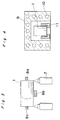
- Fig. 3 shows a diagram representing a state where the curvature portions are formed through projection of the carbon dioxide gas laser onto the corner portions.
- the preliminary raw material 1 is rotatably supported by holding members 8a,8b and 8c. By inclining these holding members 8a,8b and 8c, the preliminary raw material 1 is shifted through rotation, and therefore, the carbon dioxide gas laser 7 is also caused to slide at the same moving speed.
- the kind of glass employed for the preliminary raw material 1 is of SF6, with a diameter of 4mm and a height of 10mm.
- Table 3 below shows the laser output, number of revolutions of the optical element molding preliminary raw material, and radii of curvatures at the curvature portions according to the time for irradiation.
- the radii of curvature at the curvature portions could be readily varied through variations of the laser output, number of revolutions of the raw material and irradiation time.
- the surface roughness of the cylindrical portion extended into the end flat portion of the optical element molding material 5 by 0.1mm, and therefore, during press molding, the rough portion on the surface roughness of the cylindrical portion 3 extended into the effective diameter of the optical element, thus lowering the transmittance by about 10%.
- Fig. 4 shows a state where the curvature portions are formed through employment of the electric furnace.
- the preliminary raw material 1 placed on said support members 11 is fed for heating through a feeding port (not shown) of the electric furnace to form the curvature portions.
- the kind of glass for the preliminary raw material 1 is of SF8, with a diameter of 4.5mm, a height of 5mm, surface roughness at the flat portion of 0.1 ⁇ m, and surface roughness at the cylindrical portion of 1 ⁇ m.
- Table 5 shows the result obtained by molding 1000 pieces of the optical element molding materials processed under the conditions of the electric furnace temperature at 700°C and heating time for 60 seconds, and the result obtained by molding 1000 pieces of optical element molding materials having no curvatures at the corner portions without any processing.
- Table 5 No curvature at corner portion With curvature at corner portion Optical element chipping occurrence rate (%) 45 0 Faulty performance optical element occurrence rate (%) 37 0
- the curvature portions having the radii of curvatures of less than 0.1mm could be stably and positively produced. Meanwhile, since the optical element molding material is increased in its mechanical strength at the boundary portions, the glass material may be fed into the molding dies without chipping at such boundary portions, and no broken pieces of glass were found within the dies.
- FIG. 5 for the fourth embodiment, there is shown another molding apparatus for effecting the process of manufacturing optical elements according to the present invention.
- This molding apparatus includes an upper die 12, a lower die 13, and a barrel die 15 suitably adjusted in its height so as to remove deviation in the axes between said upper die 12 and lower die 13 and also to achieve a predetermined thickness of the optical element, with an optical element molding material 14 being fed into a space defined by the upper and lower dies 12 and 13 and the barrel die 15.
- the optical element molding preliminary raw material 14 is of the columnar shape described earlier, and its side face has the surface roughness of about 10 ⁇ m by the centerless processing, with the opposite end faces thereof being polished into a mirror face.
- the preliminary raw material 1 is thermally process, at its corner portions 14A for the opposite ends, to have required curvatures through heat processing at predetermined temperatures for a specific time by an electric furnace, and the side face of the optical element molding material 14 prepared by the above heat processing is formed into the mirror face.
- the molding material 14 thus prepared is fed into the mold so that the opposite end faces thereof contact transfer faces 12a and 13a of the upper and lower dies 12 and 13.
- a pressurizing stage 16 incorporated with a heating means (not shown) is disposed so as to receive a depressing force from a hydraulic pump or the like (not shown).
- the depressing force for the pressurizing stage 16 is arranged to be reduced to any desired pressure or the zero in the course of molding.
- the lower die 13 is placed, at its bottom flange portion 13c on a stationary molding stage 17 also incorporated with a heating means (not shown).
- a columnar material of optical glass SF8 having a diameter of 6mm ⁇ and a height of 6mm was used for the optical element molding material.
- the radius of curvature of 0.1mm was obtained when the heat processing conditions were set at 500°C for 30 minutes, with the surface roughness at the side face becoming 0.1 ⁇ m.
- the radius of curvature at the corner portion 14A should preferably be larger than 0.05mm, since if it is smaller than 0.05mm, there is a possibility that chipping takes place when the molding material 14 is charged into the dies or the upper die is brought into contact with the molding material. Meanwhile, if it is intended to make the radius of curvature larger than 1mm, the time required for the heat processing becomes very long, thus not being suitable for mass production.
- viscosity of the molding material After some time upon arrival at 530°C, viscosity of the molding material reaches 1010 poise. Then, pressure is applied to the pressurizing stage 16 and the upper die 12 starts depressing the molding material 14. At this time, the pressure should preferably be over 2kg/mm2. In the total pressurizing stroke 5mm until the flange portion 12c of the upper die 12 is brought into contact with the end face of the barrel die 15, the pressurization is once stopped upon depression up to 2.5mm, and the pressurizing stage 16 is raised to be spaced from the upper die 12 so as to reduce the pressure down to zero. Even when the pressure is reduced to zero, the upper and lower dies 12 and 13 and the molding material 14 are held in close contact with each other.
- the viscosity of the molding material 14 has reached 109 poise. Meanwhile, the spaces 12b and 13b surrounded by the die transfer faces 12a and 13a and the end faces of the molding material 14 and held in a positive pressure, return to be in normal pressure. Subsequently, after bringing the pressurizing stage 16 into close contact with the upper die 12, pressurization is again started for molding up to the total pressurizing stroke of 5mm. At this time, the spaces 12b and 13b are completely eliminated and the shape of the die transfer face has been fully transferred onto the optical element molding material 14. Thereafter, energization is suspended, and the molding material 14 is cooled down to 430°C in the pressurized state for subsequent removal of pressure to zero. Then, the mold is opened upon arrival at the room temperature for taking out the optical element. The molded optical element had the chipping occurrence rate at 0%, with a favorable performance as the optical element.
- the pressure was reduced to zero in the course of molding, the practice may be modified only to reduce pressure, since returning to the normal pressure may be achieved only through pressure reduction depending on the kind and size of the optical element molding material. It is necessary that the conditions for the heat processing to prepare the optical element molding material are properly altered depending on the kind of the raw material. Moreover, the mirror face is required for the end faces of the optical element molding material, and a cross section having a surface roughness equivalent to that of the polished face may be utilized for the purpose.
- the shape of the molding material is not limited to be the columnar shape, but may be in a rectangular parallelepiped shape, cubic shape or the like for facilitation of processing.
Landscapes
- Chemical & Material Sciences (AREA)
- Engineering & Computer Science (AREA)
- Organic Chemistry (AREA)
- Materials Engineering (AREA)
- Geochemistry & Mineralogy (AREA)
- Chemical Kinetics & Catalysis (AREA)
- General Chemical & Material Sciences (AREA)
- Life Sciences & Earth Sciences (AREA)
- Physics & Mathematics (AREA)
- Optics & Photonics (AREA)
- Thermal Sciences (AREA)
- Manufacturing & Machinery (AREA)
- Health & Medical Sciences (AREA)
- Toxicology (AREA)
- Surface Treatment Of Glass (AREA)
- Optical Elements Other Than Lenses (AREA)
- Moulds For Moulding Plastics Or The Like (AREA)
- Laser Beam Processing (AREA)
Claims (6)
- Verfahren zum Herstellen eines optischen Elements, welches die folgenden Schritte umfaßt:
Anordnen eines zu formenden Glasmaterials (1, 5, 14) für ein optisches Element in einem Raum zwischen einem ersten Formstempel (12) und einem zweiten Formstempel (13), der gegenüber dem ersten Formstempel (12) angeordnet ist, und Erzeugen des optischen Elements, wie beispielsweise einer Linse, eines Prismas oder dergleichen, durch Formen des zu formenden Glasmaterials für ein optisches Element unter Anwendung von Wärme und Formdruck, wobei das zu formende Glasmaterial (1, 5, 14) für ein optisches Element säulenförmig ausgebildet ist und einen zylindrischen Abschnitt (3, 14) sowie einander gegenüberliegende, flache Endabschnitte (2) aufweist und an jedem seiner Kantenbereiche (4, 6, 14A) zwischen dem zylindrischen Abschnitt (3, 14) und den einander gegenüberliegenden, flachen Endabschnitten (2) durch vorherige physikalische oder chemische Bearbeitung der Kantenbereiche (4, 6, 14A) des zu formenden Glasmaterials (1, 5, 14) für ein optisches Element ein Krümmungsradius größer als 0,05 mm gebildet worden ist, wobei der Schritt des Formens des zu formenden Glasmaterials für ein optisches Element unter Anwendung von Wärme und Druck so ausgeführt wird, daß der Formdruck mehr als einmal während des Formens verringert wird. - Verfahren nach Anspruch 1, bei dem der Schritt des Formens des zu formenden Glasmaterials für ein optisches Element unter Anwendung von Wärme und Druck in der Weise ausgeführt wird, daß der Formdruck während des Formens auf Null reduziert wird.
- Verfahren nach Anspruch 1, bei dem das durch Wärme und Druck zu formende Glasmaterial (1, 5, 14) für ein optisches Element durch Einwirkung der Hitze eines Kohlendioxidgaslasers (7) mit einem Krümmungsradius an jedem seiner Kantenbereiche (4, 6, 14A) ausgebildet wird.
- Verfahren nach Anspruch 1, bei dem das durch Wärme und Druck zu formende Glasmaterial (1, 5, 14) für ein optisches Element durch die Einwirkung von Hitzestrahlung mit einem Krümmungsradius an jedem seiner Kantenbereiche (4, 6, 14A) ausgebildet wird.
- Verfahren nach Anspruch 1, bei dem das durch Wärme und Druck zu formende Glasmaterial (1, 5, 14) für ein optisches Element durch chemisches Ätzen mit einem Krümmungsradius an jedem seiner Kantenbereiche (4, 6, 14A) ausgebildet wird.
- Verfahren nach einem der Ansprüche 1 bis 5, bei dem das in zylindrischer Form vorliegende, zu formende Glasmaterial (1, 5, 14) für ein optisches Element an seinen Kantenbereichen verformt wird und gleichzeitig an seinen Seitenflächen eine Rauhtiefe von weniger als 0,5 µm gebildet wird.
Applications Claiming Priority (4)
| Application Number | Priority Date | Filing Date | Title |
|---|---|---|---|
| JP154790/90 | 1990-06-13 | ||
| JP2154790A JP3024169B2 (ja) | 1990-06-13 | 1990-06-13 | 光学素子成形用素材の製造方法 |
| JP313506/90 | 1990-11-19 | ||
| JP31350690A JPH0794328B2 (ja) | 1990-11-19 | 1990-11-19 | 光学素子用ガラスプリフォーム及び光学素子の製造方法 |
Publications (2)
| Publication Number | Publication Date |
|---|---|
| EP0463463A1 EP0463463A1 (de) | 1992-01-02 |
| EP0463463B1 true EP0463463B1 (de) | 1995-09-27 |
Family
ID=26482979
Family Applications (1)
| Application Number | Title | Priority Date | Filing Date |
|---|---|---|---|
| EP91109568A Expired - Lifetime EP0463463B1 (de) | 1990-06-13 | 1991-06-11 | Verfahren zur Herstellung optischer Elemente |
Country Status (4)
| Country | Link |
|---|---|
| US (1) | US5160361A (de) |
| EP (1) | EP0463463B1 (de) |
| KR (1) | KR930006320B1 (de) |
| DE (1) | DE69113327T2 (de) |
Families Citing this family (10)
| Publication number | Priority date | Publication date | Assignee | Title |
|---|---|---|---|---|
| EP0489601B1 (de) * | 1990-12-06 | 1997-11-05 | Fujitsu Limited | Kleine Glaselektrode und Verfahren für deren Herstellung |
| US5417730A (en) * | 1991-06-25 | 1995-05-23 | Canon Kabushiki Kaisha | Apparatus for molding an optical element |
| JP3060773B2 (ja) * | 1993-03-08 | 2000-07-10 | 松下電器産業株式会社 | 光学素子の成形用材料および成形方法 |
| US5630859A (en) * | 1993-10-08 | 1997-05-20 | Matsushita Electric Industrial Co., Ltd. | Optical element forming method |
| JP2001163628A (ja) | 1999-10-01 | 2001-06-19 | Hoya Corp | 成形品の製造方法 |
| US6737661B2 (en) * | 2000-08-17 | 2004-05-18 | Novartis Ag | Pre-treatment of molds |
| JP2008285375A (ja) * | 2007-05-18 | 2008-11-27 | Panasonic Corp | 接合光学素子及びその製造方法 |
| JP2008285374A (ja) * | 2007-05-18 | 2008-11-27 | Panasonic Corp | 接合光学素子及びその製造方法 |
| JP4728280B2 (ja) * | 2007-05-18 | 2011-07-20 | パナソニック株式会社 | 接合光学素子 |
| JP2008285377A (ja) * | 2007-05-18 | 2008-11-27 | Panasonic Corp | 接合光学素子 |
Family Cites Families (13)
| Publication number | Priority date | Publication date | Assignee | Title |
|---|---|---|---|---|
| GB1358061A (en) * | 1971-05-21 | 1974-06-26 | Glaverbel | Methods of strengthening glass articles |
| JPS5422A (en) * | 1977-06-03 | 1979-01-05 | Hitachi Ltd | Glass substrate for use as indicator |
| US4481023A (en) * | 1981-10-30 | 1984-11-06 | Corning Glass Works | Process to mold precision glass articles |
| KR860001491B1 (ko) * | 1981-10-30 | 1986-09-27 | 코오닝 그라아스 와아크스 | 정밀유리제품의 성형방법 |
| DE3402648A1 (de) * | 1983-01-28 | 1984-08-02 | Canon K.K., Tokio/Tokyo | Formgebungsvorrichtung fuer ein optisches element |
| JPS60171240A (ja) * | 1984-02-15 | 1985-09-04 | Hoya Corp | ガラス表面の処理方法 |
| JPS60246231A (ja) * | 1984-05-18 | 1985-12-05 | Hitachi Ltd | レンズのプレス成形方法 |
| US4629489A (en) * | 1984-07-09 | 1986-12-16 | Hoya Corporation | Method of manufacturing pressed lenses |
| NL8702679A (nl) * | 1987-11-10 | 1989-06-01 | Philips Nv | Werkwijze voor het vervaardigen van biconvexe lenselementen. |
| JP2615886B2 (ja) * | 1988-07-28 | 1997-06-04 | 松下電器産業株式会社 | 光学部品用硝材並びに光学部品の製造方法及び光学部品 |
| DE68913860T2 (de) * | 1988-08-22 | 1994-08-04 | Matsushita Electric Ind Co Ltd | Pressform und Formgebungsverfahren zum Herstellen von optischen Teilen. |
| DE68915676T2 (de) * | 1988-10-07 | 1994-12-22 | Matsushita Electric Ind Co Ltd | Verfahren zur Herstellung von Linsen. |
| JPH02120243A (ja) * | 1988-10-27 | 1990-05-08 | Olympus Optical Co Ltd | ガラス光学素子の成形方法 |
-
1991
- 1991-06-10 US US07/712,710 patent/US5160361A/en not_active Expired - Lifetime
- 1991-06-11 EP EP91109568A patent/EP0463463B1/de not_active Expired - Lifetime
- 1991-06-11 DE DE69113327T patent/DE69113327T2/de not_active Expired - Fee Related
- 1991-06-13 KR KR1019910009707A patent/KR930006320B1/ko not_active Expired - Fee Related
Also Published As
| Publication number | Publication date |
|---|---|
| EP0463463A1 (de) | 1992-01-02 |
| KR920000630A (ko) | 1992-01-29 |
| US5160361A (en) | 1992-11-03 |
| DE69113327T2 (de) | 1996-05-02 |
| DE69113327D1 (de) | 1995-11-02 |
| KR930006320B1 (ko) | 1993-07-14 |
Similar Documents
| Publication | Publication Date | Title |
|---|---|---|
| KR860001491B1 (ko) | 정밀유리제품의 성형방법 | |
| US5346523A (en) | Method of molding chalcogenide glass lenses | |
| US5160361A (en) | Method of manufacturing optical element | |
| JPH0431328A (ja) | 光学素子成形用型構造及びプレス成形方法 | |
| US3819349A (en) | Method and apparatus for producing watch crystals | |
| JPH09249424A (ja) | 光学素子の成形法 | |
| JP2001270724A (ja) | 光学レンズ及びその成形金型 | |
| JP3203402B2 (ja) | 光学素子成形型およびその製造方法および光学素子成形方法 | |
| JP2924311B2 (ja) | ガラス光学素子の成形方法 | |
| JPS61251526A (ja) | 光学素子の製造方法 | |
| JP3024169B2 (ja) | 光学素子成形用素材の製造方法 | |
| JP2000086255A (ja) | 光学素子の成形方法 | |
| JPH05163026A (ja) | 光学素子成形用ガラス素材およびその製造方法 | |
| JPH0794328B2 (ja) | 光学素子用ガラスプリフォーム及び光学素子の製造方法 | |
| JP2618527B2 (ja) | 光学部品の製造法 | |
| JPS63295448A (ja) | ガラスレンズの成形方法 | |
| JP2814717B2 (ja) | 光学素子の成形方法 | |
| JPS6346010B2 (de) | ||
| JP4030799B2 (ja) | 光学素子の成形方法 | |
| JPS6325233A (ja) | 光学素子の加圧成形方法 | |
| JP2003054967A (ja) | プレス成形装置及び光学素子の製造方法 | |
| JPH069228A (ja) | 光学素子の成形方法 | |
| JP2930522B2 (ja) | 光学用合成石英ガラス成形体の製造方法 | |
| JPH05124824A (ja) | 光学素子素材及び光学素子の成形方法 | |
| JPS63319218A (ja) | 光学素子製造方法 |
Legal Events
| Date | Code | Title | Description |
|---|---|---|---|
| PUAI | Public reference made under article 153(3) epc to a published international application that has entered the european phase |
Free format text: ORIGINAL CODE: 0009012 |
|
| 17P | Request for examination filed |
Effective date: 19910611 |
|
| AK | Designated contracting states |
Kind code of ref document: A1 Designated state(s): DE FR GB |
|
| 17Q | First examination report despatched |
Effective date: 19940524 |
|
| GRAA | (expected) grant |
Free format text: ORIGINAL CODE: 0009210 |
|
| AK | Designated contracting states |
Kind code of ref document: B1 Designated state(s): DE FR GB |
|
| ET | Fr: translation filed | ||
| REF | Corresponds to: |
Ref document number: 69113327 Country of ref document: DE Date of ref document: 19951102 |
|
| PLBE | No opposition filed within time limit |
Free format text: ORIGINAL CODE: 0009261 |
|
| STAA | Information on the status of an ep patent application or granted ep patent |
Free format text: STATUS: NO OPPOSITION FILED WITHIN TIME LIMIT |
|
| 26N | No opposition filed | ||
| REG | Reference to a national code |
Ref country code: GB Ref legal event code: IF02 |
|
| PGFP | Annual fee paid to national office [announced via postgrant information from national office to epo] |
Ref country code: GB Payment date: 20050608 Year of fee payment: 15 Ref country code: FR Payment date: 20050608 Year of fee payment: 15 |
|
| PGFP | Annual fee paid to national office [announced via postgrant information from national office to epo] |
Ref country code: DE Payment date: 20050609 Year of fee payment: 15 |
|
| PG25 | Lapsed in a contracting state [announced via postgrant information from national office to epo] |
Ref country code: GB Free format text: LAPSE BECAUSE OF NON-PAYMENT OF DUE FEES Effective date: 20060611 |
|
| PG25 | Lapsed in a contracting state [announced via postgrant information from national office to epo] |
Ref country code: DE Free format text: LAPSE BECAUSE OF NON-PAYMENT OF DUE FEES Effective date: 20070103 |
|
| GBPC | Gb: european patent ceased through non-payment of renewal fee |
Effective date: 20060611 |
|
| REG | Reference to a national code |
Ref country code: FR Ref legal event code: ST Effective date: 20070228 |
|
| PG25 | Lapsed in a contracting state [announced via postgrant information from national office to epo] |
Ref country code: FR Free format text: LAPSE BECAUSE OF NON-PAYMENT OF DUE FEES Effective date: 20060630 |