EP0463468A1 - Dispositif de fixation d'une aiguille de pipette - Google Patents
Dispositif de fixation d'une aiguille de pipette Download PDFInfo
- Publication number
- EP0463468A1 EP0463468A1 EP91109576A EP91109576A EP0463468A1 EP 0463468 A1 EP0463468 A1 EP 0463468A1 EP 91109576 A EP91109576 A EP 91109576A EP 91109576 A EP91109576 A EP 91109576A EP 0463468 A1 EP0463468 A1 EP 0463468A1
- Authority
- EP
- European Patent Office
- Prior art keywords
- pipetting
- housing
- connection
- coupling device
- pipetting needle
- Prior art date
- Legal status (The legal status is an assumption and is not a legal conclusion. Google has not performed a legal analysis and makes no representation as to the accuracy of the status listed.)
- Withdrawn
Links
Images




Classifications
-
- G—PHYSICS
- G01—MEASURING; TESTING
- G01N—INVESTIGATING OR ANALYSING MATERIALS BY DETERMINING THEIR CHEMICAL OR PHYSICAL PROPERTIES
- G01N35/00—Automatic analysis not limited to methods or materials provided for in any single one of groups G01N1/00 - G01N33/00; Handling materials therefor
- G01N35/10—Devices for transferring samples or any liquids to, in, or from, the analysis apparatus, e.g. suction devices, injection devices
- G01N35/1081—Devices for transferring samples or any liquids to, in, or from, the analysis apparatus, e.g. suction devices, injection devices characterised by the means for relatively moving the transfer device and the containers in an horizontal plane
- G01N35/1083—Devices for transferring samples or any liquids to, in, or from, the analysis apparatus, e.g. suction devices, injection devices characterised by the means for relatively moving the transfer device and the containers in an horizontal plane with one horizontal degree of freedom
-
- B—PERFORMING OPERATIONS; TRANSPORTING
- B01—PHYSICAL OR CHEMICAL PROCESSES OR APPARATUS IN GENERAL
- B01F—MIXING, e.g. DISSOLVING, EMULSIFYING OR DISPERSING
- B01F2101/00—Mixing characterised by the nature of the mixed materials or by the application field
- B01F2101/23—Mixing of laboratory samples e.g. in preparation of analysing or testing properties of materials
Definitions
- the invention relates to a coupling device for coupling a pipetting needle to the dosing device of a pipetting system.
- the invention further relates to an automatic pipetting device which contains a coupling device according to the invention, the automatic pipetting device comprising a metering device arranged on a movable arm and a pipetting needle connected to the latter by means of a tube, which can be moved in three mutually perpendicular directions by a transport system.
- the pipetting needle is firmly connected to a cassette. These two parts form a pipetting needle-cassette unit, the pipetting needle being separably connected through the cassette and via a hose to the dosing device of the pipetting system.
- This tube is connected to the pipetting needle by a tube segment contained in the cassette.
- the pipetting needle can become blocked or damaged over time. Mainly for these reasons, it is necessary to be able to replace the tube segment and / or the pipetting needle as required.
- the invention is therefore based on the object of providing a coupling device of the type specified at the outset, with which the above-mentioned disadvantages of the known pipetting needle cassette unit can be eliminated.
- the main advantage achieved with the coupling device according to the invention is that it enables the pipetting needle or the hose segment or the housing to be replaced individually in a very simple manner.
- a coupling device according to the invention By using a coupling device according to the invention, the relatively frequent replacement of an entire pipette needle cassette unit required in the prior art can therefore be avoided. This significantly reduces the operating costs of the analysis system.
- the hose segment is arranged outside the housing. This arrangement facilitates replacement of the hose segment.
- the housing contains an electrical connection through which the pipetting needle can be connected to a level sensing arrangement.
- a coupling device serves to couple a pipetting needle 17 to the metering device 11 of a pipetting system.
- the coupling device essentially consists of a housing 15, a first connection 18, a second connection 19 and a hose segment 23.
- the housing 15 consists of an upper part 21 and a lower part 22 which are connected to one another in a separable manner.
- the housing 15 contains means for receiving and for separably attaching an end part 31 of the pipetting needle 17 to the housing 15.
- One end of the first connection 18 enables a separable connection of the coupling device to the metering device 11 of the pipetting system via a hose 16.
- a valve 32 is switched on between the coupling device and the metering device 11. Through this valve, the coupling device can be connected either to the metering device or to a washing pump, not shown.
- One end of the hose segment 23 is connected to the connector 18 and thereby to the hose 16 in a separable manner.
- the other end of the tube segment 23 is separably connected to the second connection 19 and thereby to the end part 31 of the pipetting needle 17, which is connected to the housing 15 in a separable manner.
- the hose segment 23 is arranged outside the housing 15 in a preferred embodiment.
- FIG. 2 shows an exploded, perspective view of a preferred embodiment of a coupling device according to the invention.
- the parts 21 and 22 of the housing 15 have corresponding hinge parts 26 and 27 and a locking screw 24.
- the upper housing part 21 has a connecting piece 28, by means of which the housing 15 can be detachably connected to a carrier arm of the pipetting system. After assembling the two parts 21, 22, the housing is closed by means of the screw 24.
- the screw 24 also has the function of the connector 18 in Fig. 1, i.e. it connects the hose 16 to the hose segment 23.
- the lower housing part 22 contains the means for receiving and separably attaching an end part 31 of the pipetting needle 17 to the housing 15.
- These means are essentially a bore 33 in the bottom of the housing part 21 and a slot 34 in a side wall of this part.
- the needle 17 is inserted through the bore 33.
- the upper end part 31 of the needle 17 protrudes from the housing through the slot 34 and is separably connected to one end of the hose segment 23.
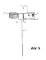
- FIG. 3 shows a view of the coupling device according to FIG. 2 in the direction Y after the connection of the upper and lower housing parts 21, 22 by means of the hinge parts 26, 27. It can be seen from this figure that the housing part 21 preferably has an electrical connection 25 contains, through which the pipetting needle 17 can be connected to a level sensing arrangement, not shown.
- FIG. 4 shows a perspective view of the coupling device according to FIG. 2 after assembly and closing of the housing 15 by means of the locking screw 24. It can be seen from FIG. 4 that the housing 15 is connected to a column 14 which is carried by a support arm (not shown) a pipetting system is carried.
- FIG. 5 shows a longitudinal section of the screw plug 24, the corresponding nut 35, sealing rings 36 and 37, a tube 39 fixedly inserted in the sealing ring 36 and a connecting part 38 connected to the sealing ring 37. All these parts form the connection 18 shown schematically in FIG. 1 between the hose 16 and the hose segment 23.
- the connection between the nut 36 and the bottom En housing part 22 can be a fixed or a separable connection.
- the connector 38 and the nut 35 are preferably made in one piece.
- the sealing ring 37 is a separate part.
- the connection part 38 and the sealing ring 37 can be produced in one piece.
- the connection part 38 protrudes through an opening of the nut 35.
- the sealing ring 36 and the tube 39 are preferably made in one piece.
- the end of the hose 16 shown in FIG. 5 is slipped over an end segment of the tube 39, so that a sufficiently sealed connection is formed between these components.
- the end of the hose segment 23 shown in FIG. 5 is slipped over an end segment of the connecting part 38, so that a sufficiently sealed connection is formed between these components.
- FIG. 6 shows a representation of the pipetting needle 17 and its connection 19 to the hose segment 23.
- One end of the hose segment 23 is slipped over an end segment of the connection 19, so that a sufficiently sealed connection is formed between these components.
- 6 also shows the connection part 38 of the connection between the hose segment 23 and the hose 16.
- FIG. 7 shows a perspective view of an automatic pipetting device which contains a coupling device according to the invention.
- the housing 15 of the coupling device is only shown schematically in FIG. 7 and does not correspond in detail to the embodiment described above according to FIGS. 2-6.
- This pipetting device contains an arm 12 which can be moved in the X direction.
- a metering device 11 is arranged on this arm.
- a carriage 13 can be moved in the Y direction along the arm 12.
- the carriage 13 carries a column 14 which is movable in the Z direction.
- the housing 15 of a coupling device according to the invention is separably connected to the column 14.
- the arm 12, the carriage 13 and the column 14 are parts of a transport system through which the pipetting needle 17 can be moved in three mutually perpendicular directions X, Y, Z. Preferably two of these directions are e.g. X and Y, in a horizontal plane.
- the arrangement of the hose segment 23 and the hose 16 can also be seen from FIG. 7.
- the piston pressure of the metering device is preferably applied to the pipetted volumes by means of a liquid, e.g. distilled water.
- the housing 15 is preferably made of a plastic that is suitable for production by an injection molding process.
- the tube segment 23 is preferably made of polytetrafluoroethylene (PTFE).
- the connections between the pipetting needle 17 and the hose segment 23 or between the hose segment 23 and the hose 16 are preferably made of polypropylene or of another plastic which is suitable for production by an injection molding process.
- the pipetting needle is e.g. made of corrosion-resistant steel. However, the material of the pipetting needle is irrelevant for the function of the coupling device and the connections used.
Landscapes
- General Health & Medical Sciences (AREA)
- Health & Medical Sciences (AREA)
- Life Sciences & Earth Sciences (AREA)
- Chemical & Material Sciences (AREA)
- Analytical Chemistry (AREA)
- Biochemistry (AREA)
- Physics & Mathematics (AREA)
- General Physics & Mathematics (AREA)
- Immunology (AREA)
- Pathology (AREA)
- Sampling And Sample Adjustment (AREA)
- Automatic Analysis And Handling Materials Therefor (AREA)
- Infusion, Injection, And Reservoir Apparatuses (AREA)
Applications Claiming Priority (2)
| Application Number | Priority Date | Filing Date | Title |
|---|---|---|---|
| CH208790 | 1990-06-22 | ||
| CH2087/90 | 1990-06-22 |
Publications (1)
| Publication Number | Publication Date |
|---|---|
| EP0463468A1 true EP0463468A1 (fr) | 1992-01-02 |
Family
ID=4225592
Family Applications (1)
| Application Number | Title | Priority Date | Filing Date |
|---|---|---|---|
| EP91109576A Withdrawn EP0463468A1 (fr) | 1990-06-22 | 1991-06-11 | Dispositif de fixation d'une aiguille de pipette |
Country Status (3)
| Country | Link |
|---|---|
| EP (1) | EP0463468A1 (fr) |
| JP (1) | JPH06100610B2 (fr) |
| CA (1) | CA2044295A1 (fr) |
Cited By (3)
| Publication number | Priority date | Publication date | Assignee | Title |
|---|---|---|---|---|
| EP0569851A1 (fr) * | 1992-05-15 | 1993-11-18 | BEHRINGWERKE Aktiengesellschaft | Dispositif de pipettage |
| EP1838423A4 (fr) * | 2005-01-10 | 2011-06-29 | Siemens Healthcare Diagnostics | Procede et dispositif pour melanger des echantillons liquides dans un contenant a l'aide d'un modele de brassage bidimensionnel |
| EP2914950A4 (fr) * | 2012-11-01 | 2016-07-20 | Leica Biosystems Melbourne Pty | Système de transport de fluide |
Citations (4)
| Publication number | Priority date | Publication date | Assignee | Title |
|---|---|---|---|---|
| US3712794A (en) * | 1971-01-26 | 1973-01-23 | Farr Devices Inc | Laboratory pipette and diluter device |
| US3747412A (en) * | 1971-10-21 | 1973-07-24 | Coulter Electronics | Sample mixing and metering apparatus |
| EP0072558A2 (fr) * | 1981-08-19 | 1983-02-23 | Tecan AG | Méthode et automate de pipettage |
| EP0202022A2 (fr) * | 1985-04-12 | 1986-11-20 | John Raymond Wells | Dispositif hydraulique de distribution de liquide |
-
1991
- 1991-06-11 EP EP91109576A patent/EP0463468A1/fr not_active Withdrawn
- 1991-06-11 CA CA002044295A patent/CA2044295A1/fr not_active Abandoned
- 1991-06-21 JP JP3150330A patent/JPH06100610B2/ja not_active Expired - Lifetime
Patent Citations (4)
| Publication number | Priority date | Publication date | Assignee | Title |
|---|---|---|---|---|
| US3712794A (en) * | 1971-01-26 | 1973-01-23 | Farr Devices Inc | Laboratory pipette and diluter device |
| US3747412A (en) * | 1971-10-21 | 1973-07-24 | Coulter Electronics | Sample mixing and metering apparatus |
| EP0072558A2 (fr) * | 1981-08-19 | 1983-02-23 | Tecan AG | Méthode et automate de pipettage |
| EP0202022A2 (fr) * | 1985-04-12 | 1986-11-20 | John Raymond Wells | Dispositif hydraulique de distribution de liquide |
Non-Patent Citations (2)
| Title |
|---|
| ANALYTICAL BIOCHEMISTRY, Band 52, Nr. 2, April 1973, Seiten 336-341, New York, NY, US; A. HENVILLE et al.: "A simple and cheap remotely-operated system for the iodination of proteins" * |
| PATENT ABSTRACTS OF JAPAN, Band 12, Nr. 143 (C-492)[2990], 30. April 1988; & JP-A-62 262 751 (NIPPON TECTRON) 14-11-1987 * |
Cited By (4)
| Publication number | Priority date | Publication date | Assignee | Title |
|---|---|---|---|---|
| EP0569851A1 (fr) * | 1992-05-15 | 1993-11-18 | BEHRINGWERKE Aktiengesellschaft | Dispositif de pipettage |
| US5365798A (en) * | 1992-05-15 | 1994-11-22 | Behringwerke Aktiengesellschaft | Pipetting device |
| EP1838423A4 (fr) * | 2005-01-10 | 2011-06-29 | Siemens Healthcare Diagnostics | Procede et dispositif pour melanger des echantillons liquides dans un contenant a l'aide d'un modele de brassage bidimensionnel |
| EP2914950A4 (fr) * | 2012-11-01 | 2016-07-20 | Leica Biosystems Melbourne Pty | Système de transport de fluide |
Also Published As
| Publication number | Publication date |
|---|---|
| JPH06100610B2 (ja) | 1994-12-12 |
| JPH06180321A (ja) | 1994-06-28 |
| CA2044295A1 (fr) | 1991-12-23 |
Similar Documents
| Publication | Publication Date | Title |
|---|---|---|
| DE69635583T2 (de) | Vorrichtung zur einführung und/oder entnahme eines mediums in einen/aus einem behälter | |
| DE69118032T2 (de) | Vorrichtung und Verfahren zur Extraktion mit überkritischen Fluiden | |
| DE102018204532A1 (de) | Servicesystem für eine Fahrzeugklimaanlage | |
| DE2658432A1 (de) | Verfahren und vorrichtung zur anbringung von behaeltern an einem gestell und zu deren verschliessen | |
| DE69920331T2 (de) | Behälter für Flüssigkeiten, insbesondere zur Analyse biologischer Flüssigkeiten | |
| EP0240604B1 (fr) | Récipient isolant avec un joint d'étanchéité élastique | |
| DE3502546A1 (de) | Analysengeraet zur messung fluessiger oder gasfoermiger proben | |
| DE69111394T2 (de) | Einwegvorrichtung zur Prüfung einer Flüssigkeit. | |
| DE69633251T2 (de) | Analyseapparat | |
| EP0444596A1 (fr) | Dispositif de prélèvement de liquides de haute pureté de récipients | |
| EP0285908A2 (fr) | Dispositif pour améliorer la qualité de l'eau potable | |
| DE1941481C3 (fr) | ||
| EP2979544A1 (fr) | Systeme d'allaitement pour betail | |
| DE2217669C3 (de) | Anordnung zum Umfüllen einer Flüssigkeit von einem ersten zu einem zweiten Gefäß | |
| DE2132066A1 (de) | Pipettiervorrichtung, zugehoerige pipetten und verfahren zum pipettieren | |
| EP0236890A1 (fr) | Dispositif pour distribuer et fabriquer des boissons à partir d'un mélange de sirop ou de concentré et d'eau | |
| DE9006868U1 (de) | Vorrichtung zum Belüften von Wasser | |
| DE4425493C2 (de) | Scheinwerfer-Reinigungsvorrichtung | |
| DE3332502A1 (de) | Volumetrische verduennungsvorrichtung | |
| DE3314780A1 (de) | Vorrichtung zur entnahme von fluessigkeiten, viskosemassen o.dgl. aus einem elastischen behaelter | |
| CH669813A5 (fr) | ||
| DE8904501U1 (de) | Vorrichtung zum Füllen und Entleeren von Proberöhrchen in der medizinischen und chemischen Analysetechnik | |
| EP2006021A1 (fr) | Partie supérieure de pipetage | |
| EP0292884B1 (fr) | Dispositif pour mélanger des matières-plastiques à plusieurs composants en particulier du polyuréthane | |
| DE4315700A1 (de) | Belüftungseinrichtung |
Legal Events
| Date | Code | Title | Description |
|---|---|---|---|
| PUAI | Public reference made under article 153(3) epc to a published international application that has entered the european phase |
Free format text: ORIGINAL CODE: 0009012 |
|
| 17P | Request for examination filed |
Effective date: 19910611 |
|
| AK | Designated contracting states |
Kind code of ref document: A1 Designated state(s): CH DE FR GB IT LI NL |
|
| STAA | Information on the status of an ep patent application or granted ep patent |
Free format text: STATUS: THE APPLICATION IS DEEMED TO BE WITHDRAWN |
|
| 18D | Application deemed to be withdrawn |
Effective date: 19940104 |