EP0463532A1 - Wrasendampfkondensatoranordnung - Google Patents
Wrasendampfkondensatoranordnung Download PDFInfo
- Publication number
- EP0463532A1 EP0463532A1 EP91109893A EP91109893A EP0463532A1 EP 0463532 A1 EP0463532 A1 EP 0463532A1 EP 91109893 A EP91109893 A EP 91109893A EP 91109893 A EP91109893 A EP 91109893A EP 0463532 A1 EP0463532 A1 EP 0463532A1
- Authority
- EP
- European Patent Office
- Prior art keywords
- vapor
- condensate
- condenser
- steam
- heat exchanger
- Prior art date
- Legal status (The legal status is an assumption and is not a legal conclusion. Google has not performed a legal analysis and makes no representation as to the accuracy of the status listed.)
- Granted
Links
Images


Classifications
-
- F—MECHANICAL ENGINEERING; LIGHTING; HEATING; WEAPONS; BLASTING
- F01—MACHINES OR ENGINES IN GENERAL; ENGINE PLANTS IN GENERAL; STEAM ENGINES
- F01K—STEAM ENGINE PLANTS; STEAM ACCUMULATORS; ENGINE PLANTS NOT OTHERWISE PROVIDED FOR; ENGINES USING SPECIAL WORKING FLUIDS OR CYCLES
- F01K9/00—Plants characterised by condensers arranged or modified to co-operate with the engines
-
- F—MECHANICAL ENGINEERING; LIGHTING; HEATING; WEAPONS; BLASTING
- F01—MACHINES OR ENGINES IN GENERAL; ENGINE PLANTS IN GENERAL; STEAM ENGINES
- F01D—NON-POSITIVE DISPLACEMENT MACHINES OR ENGINES, e.g. STEAM TURBINES
- F01D11/00—Preventing or minimising internal leakage of working-fluid, e.g. between stages
- F01D11/02—Preventing or minimising internal leakage of working-fluid, e.g. between stages by non-contact sealings, e.g. of labyrinth type
- F01D11/04—Preventing or minimising internal leakage of working-fluid, e.g. between stages by non-contact sealings, e.g. of labyrinth type using sealing fluid, e.g. steam
Definitions
- the present invention relates to a vapor condenser arrangement for condensing the leakage steam from shaft seals of a steam turbine system, the steam turbine system having a condenser and the vapor condenser arrangement containing heat exchanger surfaces which are cooled by the condensate of the condenser.
- the object of the present invention is to provide a vapor condenser arrangement in which space is saved without any other technical disadvantages while at the same time reducing costs and increasing safety.
- a vapor condenser arrangement is used to condense the leakage steam from shaft seals of a steam turbine system with heat exchanger surfaces cooled by the condensate of the condenser of the steam turbine system, in which the vapor condenser is integrated into the condensate suction line of the condenser.
- the vapor condenser forms an extension of the condensate suction line, which ends anyway for the condensate to be extracted in the condensate collecting space.
- heat exchanger tubes around which the condensate can flow are arranged, in which the vapor can condense.
- Such an arrangement means only a slight change in the line routing when the condensate is extracted.
- the vapor steam condenser can be designed as a shell-and-tube heat exchanger, the condensate entering at both ends of the heat exchanger, flowing to the center thereof and exiting into the condensate suction line in the direction of the condensate pump.
- the extension of the condensate suction line inside the condensate collection space is therefore T-shaped and the tube bundle of the vapor condenser forms the crossbar of the T.
- the condensate flows at the ends of the vapor condenser through sieve plates or filter devices, as a result of which additional sieve internals which are otherwise customary in the case of condensate suction lines can be omitted.
- the vapor condenser preferably has a multiplicity of heat exchanger tubes which are arranged between at least two tube plates, can be acted upon by the vapor vapor and can flow around the condensate.
- the dimensioning of these pipes corresponds to the amounts of leakage steam to be condensed and the usable temperature differences.
- the vapor condenser can have a guide wall in its central region, which protrudes somewhat into the condensate suction line. On this baffle, the amounts of condensate flowing in from both ends of the vapor condenser are deflected towards the condensate suction line.
- Each turbine section 1 of a steam turbine system which may consist of a plurality of turbine sections arranged on a shaft train, has shaft seals 2 which are intended to prevent steam from escaping from the casing of the turbine section into the environment.
- sealing steam from a sealing steam line 3 is additionally fed into such shaft seals, which is of secondary importance in the present context.
- the leakage steam emerging from the shaft seals 2 to a limited extent, the so-called vapor is combined in a separate vapor discharge line 4 and fed to a vapor condenser 8.
- the steam turbine system has a main condenser 6, hereinafter referred to as a condenser, for condensing the working steam.
- the condensed working steam collects at the bottom in this condenser 6 and is drawn off by a condensate pump 7 via a condensate suction line 5 and returned to the boiler arrangement of the steam turbine system.
- the condensate flowing in the condensate suction line 5 is used for cooling and condensing the vapor in the vapor condenser 8.
- the vapor vapor condenser 8 can be designed as a conventional heat exchanger, and in the installation position according to the invention, namely on the suction side of the condensate pump 7, it can be designed as an unpressurized heat exchanger.
- the vapor condenser arrangement also includes conventional installations which are expedient for operation, maintenance or as safety devices.
- a gate valve 9 enables the vapor condenser 8 to be shut off from the vapor, so that it can be discharged via an emergency loop 15 without condensation.
- a level monitor 10 monitors the liquid level.
- a suction fan 12 is connected to the vapor condenser via a shut-off valve 11.
- the flow loop 14 required for normal operation is also connected to the vapor condenser 8 via a shut-off valve 13.
- a filling line with valve 16 a minimum mass flow line 17 for receiving a minimum amount of condensate to be conveyed by the condensate pump 7, a bypass line 18 with a gate valve 19 as well as a water-side vent 20 and a water-side drain 21 are present.
- a pressureless vapor vapor condenser that, as explained with reference to FIGS. 2, 3, 4 and 5, it can be arranged in the water collecting space of the condenser 60 as an extension of the condensate suction line 75.
- various of the details described in FIG. 1 can be saved.
- this arrangement is extremely space-saving.
- the vapor steam condenser 70 is located in the condensate collection chamber 61 (often also called a hotwell) of the condenser 60, namely below the condensate level 63 and below the actual condenser floor 62.
- the end of the condensate suction line 75 located in the water collecting space 61 is preferably T-shaped with a tube collar lying in the crossbar of the T. del heat exchanger executed.
- the individual tubes 77 of the vapor condenser are fastened at both ends in tube sheets 76a, 76b and the condensate flows around them between these two tube sheets 76a, 76b.
- the condensate enters the vapor condenser 70 through sieve plates 73a, 73b, which at the same time protect the condensate pump from foreign bodies, and flows out through the condensate suction line 75 in the middle thereof.
- a guide wall 74 serves to guide the flow of condensate coming from both ends of the vapor condenser 70.
- This guide wall 74 can preferably protrude a small amount into the condensate suction line 75.
- the vapor of the steam flows through a vapor collection space 78 from the vapor supply line 71 into the pipes 77 and, in condensed form, arrives in the collection space 79 and leads to the conduit 72 starting there.
- the conduit 71, the vapor condenser 70 and the conduit 72 are mounted slightly differently from the horizontal with a gradient in Direction of the derivation 72 in order to create perfect conditions for the drainage of condensed vapor.
- the present invention leads to space and cost savings, while retaining all the advantages of known vapor condenser arrangements, in that the two related components, the main condenser and the vapor condenser, are formed as an integrated component.
Landscapes
- Engineering & Computer Science (AREA)
- Mechanical Engineering (AREA)
- General Engineering & Computer Science (AREA)
- Chemical & Material Sciences (AREA)
- Combustion & Propulsion (AREA)
- Engine Equipment That Uses Special Cycles (AREA)
- Vaporization, Distillation, Condensation, Sublimation, And Cold Traps (AREA)
- Alcoholic Beverages (AREA)
- Fixed Capacitors And Capacitor Manufacturing Machines (AREA)
- Saccharide Compounds (AREA)
Abstract
Description
- Die vorliegende Erfindung betrifft eine Wrasendampfkondensatoranordnung zur Kondensierung des Leckdampfes aus Wellendichtungen einer Dampfturbinenanlage, wobei die Dampfturbinenanlage einen Kondensator aufweist und die Wrasendampfkondensatoranordnung Wärmetauscherflächen enthält, die vom Kondensat des Kondensators gekühlt werden.
- Nach dem Stand der Technik ist es bekannt, den aus den Wellendichtungen einer Dampfturbinenanlage austretenden Leckdampf, den sogenannten Wrasendampf, in einer gesonderten Kondensatoranordnung zu kondensieren. Aus verschiedenen Gründen wird dieses Kondensat nicht dem Hauptkondensat im Hauptkondensator der Dampfturbinenanlage zugemischt, sondern getrennt abgeführt. Bisher war es nach dem Stand der Technik bekannt, den Wrasendampfkondensator in die vom Hauptkondensator zum Kessel führende Kondensatleitung zu integrieren, und zwar hinter der Kondensatpumpe, also in einem Leitungsbereich mit schon relativ hohem Druck von beispielsweise 40 bar. Bei dieser Einbaulage mußte der Wrasendampfkondensator als Druckbehälter konzipiert werden, was abgesehen von Raumproblemen auch zu relativ hohen Kosten führte.
- Aufgabe der vorliegenden Erfindung ist die Schaffung einer Wrasendampfkondensatoranordnung, bei der ohne sonstige technische Nachteile eine Raumeinsparung bei gleichzeitiger Senkung der Kosten und Erhöhung der Sicherheit erreicht wird.
- Zur Lösung dieser Aufgabe dient eine Wrasendampfkondensatoranordnung zur Kondensierung des Leckdampfes aus Wellendichtungen einer Dampfturbinenanlage mit vom Kondensat des Kondensators der Dampfturbinenanlage gekühlten Wärmetauscherflächen, bei der der Wrasendampfkondensator in die Kondensatsaugleitung des Kondensators integriert ist. Durch die zunächst einfach erscheinende Maßnahme, den Wrasendampfkondensator statt hinter der Kondensatpumpe erfindungsgemäß vor der Kondensatpumpe anzuordnen, eröffnen sich weitgehende Möglichkeiten zur Kosteneinsparung und Erhöhung der Sicherheit. Da die Saugleitung praktisch drucklos ist, braucht der Wrasendampfkondensator nicht mehr als Druckbehälter ausgelegt zu sein. Neben einer Erhöhung der Sicherheit senkt dies die Kosten bei der Herstellung und Prüfung dieses Aggregates.
- Weiter eröffnet sich die Möglichkeit, den Wrasendampfkondensator als drucklosen Wärmetauscher innerhalb des Kondensatsammelraumes unterhalb des Kondensatspiegels im Kondensator anzuordnen. Dies führt zu einer bedeutenden Platzeinsparung, ohne dabei nennenswerte Nachteile zu verursachen. Im Kondensatsammelraum des Kondensators kann genügend Platz für eine solche, relativ kleine Komponente vorgesehen werden.
- Besonders günstig ist es, wenn der Wrasendampfkondensator quasi eine Verlängerung der Kondensatsaugleitung bildet, welche ohnehin zur Absaugung des Kondensats im Kondensatsammelraum endet. Innerhalb dieser Verlängerung werden vom Kondensat umströmbare Wärmetauscherrohre angeordnet, in denen der Wrasendampfkondensieren kann. Eine solche Anordnung bedeutet nur eine geringfügige Änderung der Leitungsführung bei der Absaugung des Kondensats. Zum Erreichen des größtmöglichen Durchströmungsquerschnittes für das Kondensat kann der Wrasendampfkondensator als Rohrbündel-Wärmetauscher ausgelegt sein, wobei das Kondensat an beiden Enden des Wärmetauschers eintritt, zu dessen Mitte strömt und dort in die Kondensatsaugleitung in Richtung Kondensatpumpe austritt. Die Verlängerung der Kondensatsaugleitung im Inneren des Kondensatsammelraumes ist daher T-förmig und das Rohrbündel des Wrasendampfkondensators bildet den Querbalken des T.
- Wie anhand der Zeichnung näher erläutert wird, strömt das Kondensat an den Enden des Wrasendampfkondensators durch Siebbleche oder Filtereinrichtungen, wodurch zusätzliche, sonst bei Kondensatsaugleitungen übliche Siebeinbauten entfallen können.
- Der Wrasendampfkondensator weist vorzugsweise eine Vielzahl von zwischen mindestens zwei Rohrböden angeordneten, mit dem Wrasendampf beaufschlagbaren und vom Kondensat umströmbaren Wärmetauscherrohren auf. Die Dimensionierung dieser Rohre entspricht den zu kondensierenden Leckdampfmengen und den ausnutzbaren Temperaturdifferenzen. Der angestrebte und bekannte Vorteil, daß die gesamte dem Wrasendampf entzogene Wärme dem Kondensat zugeführt werden kann, ist auch bei der vorliegenden erfindungsgemäßen Anordnung gegeben.
- Zur Strömungsführung kann der Wrasendampfkondensator in seinem mittleren Bereich eine Leitwand aufweisen, welche etwas in die Kondensatsaugleitung hineinragt. An dieser Leitwand werden die von beiden Enden des Wrasendampfkondensators einströmenden Kondensatmengen zur Kondensatsaugleitung hin umgelenkt.
- Als günstig für den Ablauf des kondensierten Wrasendampfes hat sich eine geringfügig von der Waagerechten abweichende Anordnung erwiesen, die ein Gefälle zum Austritt des kondensierten Wrasendampfes aufweist.
- Ein Ausführungsbeispiel der Erfindung wird anhand der Zeichnung näher erläutert, und zwar zeigen
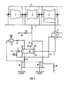
- Fig. 1 in schematischer Darstellung den prinzipiellen Aufbau einer Wrasendampfkondensatoranordnung, wobei die gegenüber dem Stand der Technik veränderte Einbaulage der Kondensatpumpe angedeutet ist, jedoch der besseren Übersichtlichkeit halber der Wrasendampfkondensator separat vom Hauptkondensator dargestellt ist,
- Fig. 2 einen Schnitt durch den unteren Teil des Hauptkondensators einer Dampfturbinenanlage in der Ebene des dort eingebauten Wrasendampfkondensators,
- Fig. 3 einen vergrößerten Längsschnitt durch den Wrasendampfkondensator selbst,
- Fig. 4 einen Querschnitt durch den Wrasendampfkondensator in der Ebene IV-IV in Fig. 3, und
- Fig. 5 einen Schnitt entlang der Linie V-V in Fig. 2 durch den unteren Teil des Hauptkondensators und den dort liegenden Wrasendampfkondensator.
- Fig. 1 zeigt schematisch den prinzipiellen Aufbau einer Wrasendampfkondensatoranordnung, wobei dieser Aufbau mit Ausnahme der Einbaulage des Wrasendampfkondensators dem Stand der Technik entspricht. Beim Stand der Technik ist allerdings der Wrasendampfkondensator druckseitig von der Kondensatpumpe angeorndet, anders als im vorliegenden Ausführungsbeispiel.
- Jede Teilturbine 1 einer ggf. aus mehreren auf einem Wellenstrang angeordneten Teilturbinen bestehenden Dampfturbinenanlage weist Wellendichtungen 2 auf, welche das Austreten von Dampf aus dem Gehäuse der Teilturbine in die Umgebung verhindern soll. Im Falle von Niederdruckteilturbinen wird in solche Wellendichtungen zusätzlich Sperrdampf aus einer Sperrdampfleitung 3 eingespeist, was jedoch im vorliegenden Zusammenhang von untergeordneter Bedeutung ist. Der aus den Wellendichtungen 2 in begrenztem Umfang austretende Leckdampf, der sogenannte Wrasendampf, wird in einer gesonderten Wrasendampfableitung 4 zusammengefaßt und einem Wrasendampfkondensator 8 zugeführt. Die Dampfturbinenanlage weist einen Hauptkondensator 6, im folgenden als Kondensator bezeichnet, zur Kondensation des Arbeitsdampfes auf. Der kondensierte Arbeitsdampf sammelt sich unten in diesem Kondensator 6 und wird über eine Kondensatsaugleitung 5 von einer Kondensatpumpe 7 abgesaugt und zur Kesselanordnung der Dampfturbinenanlage zurückgeführt. Das in der Kondensatsaugleitung 5 fließende Kondensat wird zur Kühlung und Kondensation des Wrasendampfes im Wrasendampfkondensator 8 ausgenutzt. Dadurch wird die dem Wrasendampf entzogene Wärme vollständig dem Kondensat zugeführt und bleibt damit für den Dampfturbineprozeß nutzbar. Der Wrasendampfkondensator 8 kann als üblicher Wärmetauscher ausgelegt sein, wobei er in der erfindungsgemäßen Einbaulage, nämlich saugseitig der Kondensatpumpe 7 als druckloser Wärmetauscher ausgelegt sein kann. Zu der Wrasendampfkondensatoranordnung gehören noch übliche Installationen, die zum Betrieb, zur Wartung oder als Sicherheitseinrichtungen sinnvoll sind. Ein Absperrschieber 9 ermöglicht die Absperrung des Wrasendampfkondensators 8 gegenüber dem Wrasendampf, so daß dieser über eine Notschleife 15 ohne Kondensation abgelassen werden kann. Ein Niveauwächter 10 überwacht den Flüssigkeitsstand. Über ein Absperrventil 11 ist ein Sauggebläse 12 an den Wrasendampfkondensator angeschlossen. Auch die für den Normalbetrieb benötigte Ablaufschleife 14 ist über ein Absperrventil 13 mit dem Wrasendampfkondensator 8 verbunden. Weiterhin sind eine Fülleitung mit Ventil 16, eine Mindestmassenstromleitung 17 zur Aufnahme einer Mindestmenge an von der Kondensatpumpe 7 zu fördernden Kondensates, eine Umführungsleitung 18 mit Absperrschieber 19 sowie eine wasserseitige Entlüftung 20 und eine wasserseitige Entleerung 21 vorhanden.
- Besonders vorteilhaft ist es bei diesem Konzept eines drucklosen Wrasendampfkondensators, daß dieser, wie anhand der Fig. 2, 3, 4 und 5 erläutert, im Wassersammelraum des Kondensators 60 als Verlängerung der Kondensatsaugleitung 75 angeordnet werden kann. Hierdurch können verschiedene der in Fig. 1 beschriebenen Einzelheiten eingespart werden. Außerdem ist diese Anordnung außerordentlich platzsparend. Der Wrasendampfkondensator 70 liegt im Kondensatsammelraum 61 (oft auch Hotwell genannt) des Kondensators 60, und zwar unterhalb des Kondensatspiegels 63 und unterhalb des eigentlichen Kondensatorbodens 62. Die Wrasendampfzuleitung 71 und die Ableitung 72 für kondensierten Wrasendampf sind durch die Wände des Wassersammelraumes 61 geführt. Das im Wassersammelraum 61 liegende Ende der Kondensatsaugleitung 75 ist bevorzugt T-förmig mit einem im Querbalken des T liegenden Rohrbündelwärmetauscher ausgeführt. Die einzelnen Rohre 77 des Wrasendampfkondensators sind an beiden Enden in Rohrböden 76a, 76b befestigt und werden zwischen diesen beiden Rohrböden 76a, 76b vom Kondensat umströmt. Das Kondensat gelangt durch Siebbleche 73a, 73b, die gleichzeitig die Kondensatpumpe vor Fremdkörpern schützen, in den Wrasendampfkondensator 70 und strömt in dessen Mitte durch die Kondensatsaugleitung 75 ab. Eine Leitwand 74 dient der Strömungsführung der von beiden Enden des Wrasendampfkondensators 70 kommenden Kondensats. Diese Leitwand 74 kann vorzugsweise ein kleines Stück in die Kondensatsaugleitung 75 ragen. Der Wrasendampf strömt über einen Wrasendampfsammelraum 78 aus der Wrasendampfzuleitung 71 in die Rohre 77 und gelangt in kondensierter Form in den Sammelraum 79 und zur dort beginnenden Ableitung 72. Zuleitung 71, Wrasendampfkondensator 70 und Ableitung 72 sind geringfügig von der Waagerechten abweichend montiert mit einem Gefälle in Richtung der Ableitung 72, um einwandfreie Verhältnisse für das Ablaufen von kondensiertem Wrasendampf zu schaffen.
- Die vorliegende Erfindung führt unter Beibehaltung aller Vorteile bekannter Wrasendampfkondensatoranordnungen zu Platz- und Kosteneinsparungen, in dem die beiden verwandten Bauteile Hauptkondensator und Wrasendampfkondensator als integriertes Bauteil ausgebildet werden.
Claims (8)
Applications Claiming Priority (2)
| Application Number | Priority Date | Filing Date | Title |
|---|---|---|---|
| DE4020587A DE4020587A1 (de) | 1990-06-28 | 1990-06-28 | Wrasendampfkondensatoranordnung |
| DE4020587 | 1990-06-28 |
Publications (2)
| Publication Number | Publication Date |
|---|---|
| EP0463532A1 true EP0463532A1 (de) | 1992-01-02 |
| EP0463532B1 EP0463532B1 (de) | 1994-04-20 |
Family
ID=6409254
Family Applications (1)
| Application Number | Title | Priority Date | Filing Date |
|---|---|---|---|
| EP91109893A Expired - Lifetime EP0463532B1 (de) | 1990-06-28 | 1991-06-17 | Wrasendampfkondensatoranordnung |
Country Status (6)
| Country | Link |
|---|---|
| EP (1) | EP0463532B1 (de) |
| AT (1) | ATE104744T1 (de) |
| DE (2) | DE4020587A1 (de) |
| DK (1) | DK0463532T3 (de) |
| ES (1) | ES2051541T3 (de) |
| FI (1) | FI912655A7 (de) |
Cited By (3)
| Publication number | Priority date | Publication date | Assignee | Title |
|---|---|---|---|---|
| DE4313805A1 (de) * | 1993-04-27 | 1994-11-03 | Siemens Ag | Dichtungsanordnung für zumindest eine Durchführung einer Welle durch ein Gehäuse |
| CN113218203A (zh) * | 2021-06-11 | 2021-08-06 | 西安热工研究院有限公司 | 一种适用于单流程表面式水冷凝汽器导流防砸系统 |
| IT202100002348A1 (it) * | 2021-02-03 | 2022-08-03 | Nuovo Pignone Tecnologie Srl | Gland condenser skid systems by shell & plates technology |
Families Citing this family (1)
| Publication number | Priority date | Publication date | Assignee | Title |
|---|---|---|---|---|
| DE102007021742B4 (de) * | 2007-05-09 | 2009-04-09 | Siemens Ag | Wellendichtung für Dampfturbinen |
Citations (5)
| Publication number | Priority date | Publication date | Assignee | Title |
|---|---|---|---|---|
| CH143107A (de) * | 1929-11-20 | 1930-10-31 | Oerlikon Maschf | Verfahren zur Verminderung des Gasgehaltes in dem aus Oberflächenkondensatoren von Dampfkraftanlagen abzuführenden Kondensat. |
| GB781505A (en) * | 1955-01-31 | 1957-08-21 | English Electric Co Ltd | Improvements in and relating to condensing steam turbines |
| US3705494A (en) * | 1971-01-04 | 1972-12-12 | Fester Wheeler Corp | Holding system for steam power cycle |
| DE3333530A1 (de) * | 1982-09-17 | 1984-04-12 | Hitachi, Ltd., Tokyo | Vakuumrueckhalteeinrichtung |
| US4793141A (en) * | 1986-11-14 | 1988-12-27 | Hitachi, Ltd. | Gland sealing steam supply system for steam turbines |
Family Cites Families (1)
| Publication number | Priority date | Publication date | Assignee | Title |
|---|---|---|---|---|
| US3194021A (en) * | 1964-07-14 | 1965-07-13 | Westinghouse Electric Corp | Vapor condensing apparatus |
-
1990
- 1990-06-28 DE DE4020587A patent/DE4020587A1/de not_active Withdrawn
-
1991
- 1991-06-03 FI FI912655A patent/FI912655A7/fi not_active Application Discontinuation
- 1991-06-17 DE DE59101424T patent/DE59101424D1/de not_active Expired - Fee Related
- 1991-06-17 AT AT9191109893T patent/ATE104744T1/de not_active IP Right Cessation
- 1991-06-17 EP EP91109893A patent/EP0463532B1/de not_active Expired - Lifetime
- 1991-06-17 ES ES91109893T patent/ES2051541T3/es not_active Expired - Lifetime
- 1991-06-17 DK DK91109893.7T patent/DK0463532T3/da active
Patent Citations (5)
| Publication number | Priority date | Publication date | Assignee | Title |
|---|---|---|---|---|
| CH143107A (de) * | 1929-11-20 | 1930-10-31 | Oerlikon Maschf | Verfahren zur Verminderung des Gasgehaltes in dem aus Oberflächenkondensatoren von Dampfkraftanlagen abzuführenden Kondensat. |
| GB781505A (en) * | 1955-01-31 | 1957-08-21 | English Electric Co Ltd | Improvements in and relating to condensing steam turbines |
| US3705494A (en) * | 1971-01-04 | 1972-12-12 | Fester Wheeler Corp | Holding system for steam power cycle |
| DE3333530A1 (de) * | 1982-09-17 | 1984-04-12 | Hitachi, Ltd., Tokyo | Vakuumrueckhalteeinrichtung |
| US4793141A (en) * | 1986-11-14 | 1988-12-27 | Hitachi, Ltd. | Gland sealing steam supply system for steam turbines |
Cited By (6)
| Publication number | Priority date | Publication date | Assignee | Title |
|---|---|---|---|---|
| DE4313805A1 (de) * | 1993-04-27 | 1994-11-03 | Siemens Ag | Dichtungsanordnung für zumindest eine Durchführung einer Welle durch ein Gehäuse |
| US5632492A (en) * | 1993-04-27 | 1997-05-27 | Siemens Aktiengesellschaft | Sealing configuration for a passage of a shaft through a casing and method of operating the sealing configuration |
| IT202100002348A1 (it) * | 2021-02-03 | 2022-08-03 | Nuovo Pignone Tecnologie Srl | Gland condenser skid systems by shell & plates technology |
| WO2022167147A1 (en) * | 2021-02-03 | 2022-08-11 | Nuovo Pignone Tecnologie - S.R.L. | Gland condenser skid systems by shell & plates technology |
| US12560107B2 (en) | 2021-02-03 | 2026-02-24 | Nuovo Pignone Tecnologie—SRL | Gland condenser skid systems by shell and plates technology |
| CN113218203A (zh) * | 2021-06-11 | 2021-08-06 | 西安热工研究院有限公司 | 一种适用于单流程表面式水冷凝汽器导流防砸系统 |
Also Published As
| Publication number | Publication date |
|---|---|
| DK0463532T3 (da) | 1994-09-12 |
| DE59101424D1 (de) | 1994-05-26 |
| ES2051541T3 (es) | 1994-06-16 |
| ATE104744T1 (de) | 1994-05-15 |
| FI912655A7 (fi) | 1991-12-29 |
| FI912655A0 (fi) | 1991-06-03 |
| EP0463532B1 (de) | 1994-04-20 |
| DE4020587A1 (de) | 1992-01-02 |
Similar Documents
| Publication | Publication Date | Title |
|---|---|---|
| DE102008005077A1 (de) | Plattenverdampfer, insbesondere für einen Kältemittelkreis | |
| EP1320665B1 (de) | Verfahren zum betreiben einer gas- und dampfturbinenanlage sowie entsprechende anlage | |
| DE2458471C2 (de) | Speisewasservorwaermer mit zwei dampfraeumen | |
| EP0463532B1 (de) | Wrasendampfkondensatoranordnung | |
| DE3636491C2 (de) | Würzekochvorrichtung | |
| EP0619466B1 (de) | Dampfkondensator | |
| DE2608985C3 (de) | Speisewasserbehälter für ein Dampfkraftwerk | |
| CH625031A5 (de) | ||
| DE2717505A1 (de) | Zweistufiger verdampfer | |
| DE102019005769A1 (de) | Luftgekühlte Kondensatoranlage | |
| DE2917498C2 (de) | Oberflächen-Wärmetauscher | |
| DE2417163C3 (de) | Kondensator für eine Dampfan-Wasser-Kondensation | |
| DE10016080A1 (de) | Kondensator | |
| DE2164574C3 (de) | Einrichtung zum Entgasen von schwach radioaktiven Kondensaten in Kernkraftwerken | |
| EP1249662B1 (de) | Dampferzeuger | |
| DE10031789A1 (de) | Kombi-oder Dampfkraftanlage | |
| EP1577626A1 (de) | Luftbeaufschlagter Trockenkühler zum Kondensieren von Wasserdampf | |
| DE2942490C2 (de) | Kraftwerkswärmetauscher | |
| DE19949761B4 (de) | Mehrdruckkondensationsanlage | |
| DE1501346A1 (de) | Luftgekuehlter Kondensator | |
| DE19511264C2 (de) | Wärmetauscher | |
| DE475051C (de) | Vorwaermer | |
| EP1777477B1 (de) | Kondensator für den Wasser-Dampf-Kreislauf einer Kraftwerksanlage | |
| DE3419045C2 (de) | ||
| EP2336696B1 (de) | Modifizierte Hybrid Kühlanlage mit getrennten Kreisläufen |
Legal Events
| Date | Code | Title | Description |
|---|---|---|---|
| PUAI | Public reference made under article 153(3) epc to a published international application that has entered the european phase |
Free format text: ORIGINAL CODE: 0009012 |
|
| AK | Designated contracting states |
Kind code of ref document: A1 Designated state(s): AT BE CH DE DK ES FR GB IT LI NL SE |
|
| 17P | Request for examination filed |
Effective date: 19920128 |
|
| 17Q | First examination report despatched |
Effective date: 19930913 |
|
| GRAA | (expected) grant |
Free format text: ORIGINAL CODE: 0009210 |
|
| AK | Designated contracting states |
Kind code of ref document: B1 Designated state(s): AT BE CH DE DK ES FR GB IT LI NL SE |
|
| REF | Corresponds to: |
Ref document number: 104744 Country of ref document: AT Date of ref document: 19940515 Kind code of ref document: T |
|
| REF | Corresponds to: |
Ref document number: 59101424 Country of ref document: DE Date of ref document: 19940526 |
|
| REG | Reference to a national code |
Ref country code: ES Ref legal event code: FG2A Ref document number: 2051541 Country of ref document: ES Kind code of ref document: T3 |
|
| ITF | It: translation for a ep patent filed | ||
| GBT | Gb: translation of ep patent filed (gb section 77(6)(a)/1977) |
Effective date: 19940715 |
|
| ET | Fr: translation filed | ||
| REG | Reference to a national code |
Ref country code: DK Ref legal event code: T3 |
|
| EAL | Se: european patent in force in sweden |
Ref document number: 91109893.7 |
|
| PLBE | No opposition filed within time limit |
Free format text: ORIGINAL CODE: 0009261 |
|
| STAA | Information on the status of an ep patent application or granted ep patent |
Free format text: STATUS: NO OPPOSITION FILED WITHIN TIME LIMIT |
|
| 26N | No opposition filed | ||
| PGFP | Annual fee paid to national office [announced via postgrant information from national office to epo] |
Ref country code: AT Payment date: 19960530 Year of fee payment: 6 |
|
| PGFP | Annual fee paid to national office [announced via postgrant information from national office to epo] |
Ref country code: ES Payment date: 19960611 Year of fee payment: 6 |
|
| PGFP | Annual fee paid to national office [announced via postgrant information from national office to epo] |
Ref country code: BE Payment date: 19960612 Year of fee payment: 6 |
|
| PGFP | Annual fee paid to national office [announced via postgrant information from national office to epo] |
Ref country code: DK Payment date: 19960620 Year of fee payment: 6 |
|
| PGFP | Annual fee paid to national office [announced via postgrant information from national office to epo] |
Ref country code: FR Payment date: 19960625 Year of fee payment: 6 |
|
| PG25 | Lapsed in a contracting state [announced via postgrant information from national office to epo] |
Ref country code: DK Free format text: LAPSE BECAUSE OF NON-PAYMENT OF DUE FEES Effective date: 19970617 Ref country code: AT Effective date: 19970617 |
|
| REG | Reference to a national code |
Ref country code: DK Ref legal event code: EBP |
|
| PG25 | Lapsed in a contracting state [announced via postgrant information from national office to epo] |
Ref country code: ES Free format text: LAPSE BECAUSE OF NON-PAYMENT OF DUE FEES Effective date: 19970618 |
|
| PG25 | Lapsed in a contracting state [announced via postgrant information from national office to epo] |
Ref country code: BE Effective date: 19970630 |
|
| BERE | Be: lapsed |
Owner name: SIEMENS A.G. Effective date: 19970630 |
|
| PG25 | Lapsed in a contracting state [announced via postgrant information from national office to epo] |
Ref country code: FR Free format text: LAPSE BECAUSE OF NON-PAYMENT OF DUE FEES Effective date: 19980227 |
|
| REG | Reference to a national code |
Ref country code: FR Ref legal event code: ST |
|
| REG | Reference to a national code |
Ref country code: FR Ref legal event code: ST |
|
| PGFP | Annual fee paid to national office [announced via postgrant information from national office to epo] |
Ref country code: GB Payment date: 19980511 Year of fee payment: 8 |
|
| PGFP | Annual fee paid to national office [announced via postgrant information from national office to epo] |
Ref country code: SE Payment date: 19980615 Year of fee payment: 8 |
|
| PGFP | Annual fee paid to national office [announced via postgrant information from national office to epo] |
Ref country code: NL Payment date: 19980629 Year of fee payment: 8 |
|
| PGFP | Annual fee paid to national office [announced via postgrant information from national office to epo] |
Ref country code: DE Payment date: 19980819 Year of fee payment: 8 |
|
| PGFP | Annual fee paid to national office [announced via postgrant information from national office to epo] |
Ref country code: CH Payment date: 19980911 Year of fee payment: 8 |
|
| PG25 | Lapsed in a contracting state [announced via postgrant information from national office to epo] |
Ref country code: GB Free format text: LAPSE BECAUSE OF NON-PAYMENT OF DUE FEES Effective date: 19990617 |
|
| PG25 | Lapsed in a contracting state [announced via postgrant information from national office to epo] |
Ref country code: SE Free format text: THE PATENT HAS BEEN ANNULLED BY A DECISION OF A NATIONAL AUTHORITY Effective date: 19990629 |
|
| PG25 | Lapsed in a contracting state [announced via postgrant information from national office to epo] |
Ref country code: LI Free format text: LAPSE BECAUSE OF NON-PAYMENT OF DUE FEES Effective date: 19990630 Ref country code: CH Free format text: LAPSE BECAUSE OF NON-PAYMENT OF DUE FEES Effective date: 19990630 |
|
| PG25 | Lapsed in a contracting state [announced via postgrant information from national office to epo] |
Ref country code: NL Free format text: LAPSE BECAUSE OF NON-PAYMENT OF DUE FEES Effective date: 20000101 |
|
| GBPC | Gb: european patent ceased through non-payment of renewal fee |
Effective date: 19990617 |
|
| REG | Reference to a national code |
Ref country code: CH Ref legal event code: PL |
|
| EUG | Se: european patent has lapsed |
Ref document number: 91109893.7 |
|
| NLV4 | Nl: lapsed or anulled due to non-payment of the annual fee |
Effective date: 20000101 |
|
| REG | Reference to a national code |
Ref country code: ES Ref legal event code: FD2A Effective date: 20000403 |
|
| PG25 | Lapsed in a contracting state [announced via postgrant information from national office to epo] |
Ref country code: DE Free format text: LAPSE BECAUSE OF NON-PAYMENT OF DUE FEES Effective date: 20000503 |
|
| PG25 | Lapsed in a contracting state [announced via postgrant information from national office to epo] |
Ref country code: IT Free format text: LAPSE BECAUSE OF NON-PAYMENT OF DUE FEES;WARNING: LAPSES OF ITALIAN PATENTS WITH EFFECTIVE DATE BEFORE 2007 MAY HAVE OCCURRED AT ANY TIME BEFORE 2007. THE CORRECT EFFECTIVE DATE MAY BE DIFFERENT FROM THE ONE RECORDED. Effective date: 20050617 |