EP0463564A2 - Système de bâti pour la construction d'installation à courant faible - Google Patents
Système de bâti pour la construction d'installation à courant faible Download PDFInfo
- Publication number
- EP0463564A2 EP0463564A2 EP91110131A EP91110131A EP0463564A2 EP 0463564 A2 EP0463564 A2 EP 0463564A2 EP 91110131 A EP91110131 A EP 91110131A EP 91110131 A EP91110131 A EP 91110131A EP 0463564 A2 EP0463564 A2 EP 0463564A2
- Authority
- EP
- European Patent Office
- Prior art keywords
- vertical supports
- frame
- columns
- rack system
- open
- Prior art date
- Legal status (The legal status is an assumption and is not a legal conclusion. Google has not performed a legal analysis and makes no representation as to the accuracy of the status listed.)
- Ceased
Links
Images

Classifications
-
- H—ELECTRICITY
- H05—ELECTRIC TECHNIQUES NOT OTHERWISE PROVIDED FOR
- H05K—PRINTED CIRCUITS; CASINGS OR CONSTRUCTIONAL DETAILS OF ELECTRIC APPARATUS; MANUFACTURE OF ASSEMBLAGES OF ELECTRICAL COMPONENTS
- H05K7/00—Constructional details common to different types of electric apparatus
- H05K7/18—Construction of rack or frame
- H05K7/183—Construction of rack or frame support rails therefor
Definitions
- the present invention relates to a rack system for low-current plant construction, in particular for distribution systems, which can be assembled from several units according to the modular principle, which units in particular cable-carrying vertical supports for the attachment of terminal strips and. Like. Include.
- rack systems of the aforementioned type are becoming increasingly important in order to be able to wire the supply lines, which are growing rapidly in number, in a clear and efficient manner.
- the aim here is to design such frame systems as building blocks in order to build the frames from standardized ones To improve parts economically on the basis of a model plan or the like.
- the vertical supports are U-profile-like columns which are open towards the front and which, when assembled, form a self-supporting frame and whose open-sided surfaces close to the edges have grid perforations for the assembly of system elements, the clear width of the vertical supports is a measure of the system module and itself support the vertical beams on at least one common floor rail or the like.
- the common bottom rail is a central rail supported by vertical supports.
- the vertical supports are self-supportingly composed of angle profiles, of which at least one pair form a box-profile-like column that is open at the front, possibly at the rear, and those angle profile sections that form the side walls are connected by spacer webs that determine the modular system distance and that two pairs of angle profiles are joined to form a double column accessible from the front and rear, the angle profile sections of each angle profile pair forming the flanges being connected to one another.
- angle profiles have perforations for releasable fastening to one another or to the spacer webs or to other units of the system.
- a compact, stable, accessible from all sides, free-standing arrangement also arises when the columns carry upper and lower covers, which at the same time mounting aids for an upper stabilization rail or. Form the frame feet.
- the vertical supports formed by columns can also be connected to those in horizontal extension.
- the rack system illustrated in FIGS. 1 to 3 is constructed here in two modules and comprises first vertical supports 1 for a so-called "VS 83" distributor and a second vertical support 1 'for attaching the 19' 'instrumentation for signal transmission from and which is common today to data processing systems as a rule.
- the vertical supports 1 and 1 ' are, in a manner known per se, U-profile-like columns which are open towards the front and which, when put together, form a self-supporting frame and their open-sided edges near the edges 2,2 'perforations 3 respectively. 3 'for assembling system elements not shown in detail (Fig. 3).
- each column 1 or. 1 'a measure of the module in question As can be seen in particular in FIG. 2, the clear width of each column 1 or. 1 'a measure of the module in question. Furthermore, the surfaces 2 (FIG. 2) near the edges can be drawn in or the surfaces 2 '(FIG. 2) can run parallel.
- the columns 1 of the first modular system and the columns 1 'of the second modular system are supported on a preferably central floor rail 4, which at a location with a double floor 5 (FIG. 1) is preferably adjustable in height Support 6 are supported (Fig. 1). This allows an optimal cable entry and entry from below, the open construction also allowing a cable entry from above, as shown in FIG. 1 with the upper cable duct 7.
- the vertical supports 1 of the first modular system are folded profiles, whereas the vertical supports 1 'of the second modular system are modularly assembled from angle profiles, as can be seen from FIG. 3.
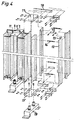
- the first modular frame part can also be created on site using a modular system, as shown in FIG. 4 for a single-modular "VS 83" distributor.
- each individual column itself being composed of two angle profiles 12, 13 and thus forming an open box profile.
- the angle profile sections forming the side walls 12 are connected by spacer webs 14 which determine the modular system distance. Additional spacer plates 15 or the like can also connect the angle profile sections forming the flanges 13, so that a self-supporting, detachable column is created.
- a compact design with double columns 11, 11 'accessible from the front and rear results from the fact that the angle profile sections of each pair of angle profiles forming the flanges 13 are connected to one another so as to lie against one another.
- Such double columns 11, 11 ' can then guide the cables in their channel-like area, the spacer plates 15 on the flanges 13 separating the channels of the individual columns 11 and 11' from one another and the spacer webs 14 on the open one On the side of the channels, secure against the cable strands falling out of the relevant vertical support.
- the connecting strips corresponding to the selected module can then be attached to these columns in the usual manner and as described with reference to FIGS. 1-3. Mount the like (not shown).
- upper 17 and lower covers 17 ' can also be connected to the columns 11, 11', which at the same time act as assembly aids for the assembly of upper stabilization rails 18, which can also be designed as transverse channels resp.
- Frame feet 19 serve.
- the column 1 'of the second modular system according to FIGS. 1 to 3 can also be constructed in the same way.
- a frame system thus results from the above for low-voltage plant construction, in particular for distribution systems, which now meets all requirements, whereby a self-supporting, individual, very versatile and particularly compact structure is achieved with a few basic elements, with optimal handling from the front and rear, and now in particular a multi-modular design is possible, for example the combination of the "VS 83" channel system with a 19 "channel system.
Landscapes
- Engineering & Computer Science (AREA)
- Microelectronics & Electronic Packaging (AREA)
- Patch Boards (AREA)
- Details Of Indoor Wiring (AREA)
- Installation Of Indoor Wiring (AREA)
Applications Claiming Priority (2)
| Application Number | Priority Date | Filing Date | Title |
|---|---|---|---|
| CH2157/90 | 1990-06-28 | ||
| CH215790A CH680891A5 (fr) | 1990-06-28 | 1990-06-28 |
Publications (2)
| Publication Number | Publication Date |
|---|---|
| EP0463564A2 true EP0463564A2 (fr) | 1992-01-02 |
| EP0463564A3 EP0463564A3 (en) | 1993-01-20 |
Family
ID=4227218
Family Applications (1)
| Application Number | Title | Priority Date | Filing Date |
|---|---|---|---|
| EP19910110131 Ceased EP0463564A3 (en) | 1990-06-28 | 1991-06-20 | Rack system for the construction of electrical low-current installation |
Country Status (5)
| Country | Link |
|---|---|
| EP (1) | EP0463564A3 (fr) |
| CH (1) | CH680891A5 (fr) |
| CZ (1) | CZ280026B6 (fr) |
| HU (1) | HU216264B (fr) |
| PL (1) | PL165611B1 (fr) |
Cited By (1)
| Publication number | Priority date | Publication date | Assignee | Title |
|---|---|---|---|---|
| FR2711019A1 (fr) * | 1993-10-06 | 1995-04-14 | Schroff Gmbh | Armoire à appareils. |
Family Cites Families (4)
| Publication number | Priority date | Publication date | Assignee | Title |
|---|---|---|---|---|
| GB1101356A (en) * | 1964-05-04 | 1968-01-31 | C & N Electrical Ltd | Improvements in or relating to structural members and arrangements, particularly for use with modular units of equipment |
| DE7211693U (de) * | 1972-03-27 | 1972-06-22 | Siemens Ag | Schrank zur Aufnahme elektronischer Einrichtungen |
| FR2566222B1 (fr) * | 1984-06-15 | 1988-01-29 | Alsthom Atlantique | Assemblage en triedre |
| DE8601620U1 (de) * | 1986-01-23 | 1986-07-03 | TES Hans Tappert, 4018 Langenfeld | Computergehäuse |
-
1990
- 1990-06-28 CH CH215790A patent/CH680891A5/de not_active IP Right Cessation
-
1991
- 1991-06-20 EP EP19910110131 patent/EP0463564A3/de not_active Ceased
- 1991-06-27 PL PL29083391A patent/PL165611B1/pl unknown
- 1991-06-27 HU HU912164A patent/HU216264B/hu not_active IP Right Cessation
- 1991-06-28 CZ CS911983A patent/CZ280026B6/cs unknown
Cited By (1)
| Publication number | Priority date | Publication date | Assignee | Title |
|---|---|---|---|---|
| FR2711019A1 (fr) * | 1993-10-06 | 1995-04-14 | Schroff Gmbh | Armoire à appareils. |
Also Published As
| Publication number | Publication date |
|---|---|
| CZ280026B6 (cs) | 1995-09-13 |
| HU912164D0 (en) | 1991-12-30 |
| EP0463564A3 (en) | 1993-01-20 |
| HU216264B (hu) | 1999-05-28 |
| CH680891A5 (fr) | 1992-11-30 |
| PL290833A1 (en) | 1992-03-09 |
| PL165611B1 (pl) | 1995-01-31 |
| CS198391A3 (en) | 1992-04-15 |
| HUH3648A (en) | 1992-12-28 |
Similar Documents
| Publication | Publication Date | Title |
|---|---|---|
| EP0140014B1 (fr) | Système de bâti pour installation à courant faible, plus spécialement pour installations de distribution | |
| DE69216078T2 (de) | Modulare paneelwandanordnung | |
| DE69701988T2 (de) | Versetzbares trennwandsystem | |
| DE68904706T2 (de) | Verfahren zur montage von mindestens einem elektrischen geraet auf einem traeger. | |
| EP1287798A1 (fr) | Dispositif visant la fabrication des produits d'hygiène | |
| CH680891A5 (fr) | ||
| DE2309935C3 (de) | Installationskanal für elektrische und/oder gastechnische Einrichtungen | |
| EP0594157A1 (fr) | Cabane de bois | |
| DE2846948C2 (de) | Flächenkabelrost | |
| DE19721557A1 (de) | Verteilerschrank mit einem Verteilergestell | |
| DE29704305U1 (de) | Geräteschrank | |
| DE3706797A1 (de) | Gestell-system fuer den schwachstrom-anlagebau, insbesondere fuer verteiler-anlagen | |
| DE2516598C3 (de) | Anordnung zur Befestigung von Trägerschienen an Profilrahmen | |
| DE2802710C2 (de) | Aus mehreren Gestellen bestehende Gestellanordnung | |
| DE9110389U1 (de) | Tragvorrichtung für Schalt- und Steuergeräte | |
| DE2750517C3 (de) | Flächenkabelträger zum Einsatz insbesondere in Telephonzentralen und Verstärkerstellen (TZV) | |
| DE8910310U1 (de) | Rahmengestell für Schaltschränke | |
| DE3107484C2 (de) | Kabelträgersystem | |
| DE9312589U1 (de) | Niederspannungs-Schaltanlage mit einem in einem Gerüst abgestützten Träger für Schalt- und/oder Steuergeräte | |
| CH503395A (de) | Verteilerkasten für elektrische Installationen | |
| AT205570B (de) | Elektrische Schalttafel | |
| DE102004059408A1 (de) | Rahmengestell | |
| DE19627537C2 (de) | Wandverteilergestell | |
| DE2407702A1 (de) | Bauelementesystem fuer rahmengestelle | |
| DE9412167U1 (de) | Wandverteiler |
Legal Events
| Date | Code | Title | Description |
|---|---|---|---|
| PUAI | Public reference made under article 153(3) epc to a published international application that has entered the european phase |
Free format text: ORIGINAL CODE: 0009012 |
|
| AK | Designated contracting states |
Kind code of ref document: A2 Designated state(s): DE FR GB IT |
|
| PUAL | Search report despatched |
Free format text: ORIGINAL CODE: 0009013 |
|
| AK | Designated contracting states |
Kind code of ref document: A3 Designated state(s): DE FR GB IT |
|
| 17P | Request for examination filed |
Effective date: 19930709 |
|
| 17Q | First examination report despatched |
Effective date: 19941118 |
|
| STAA | Information on the status of an ep patent application or granted ep patent |
Free format text: STATUS: THE APPLICATION HAS BEEN REFUSED |
|
| 18R | Application refused |
Effective date: 19960408 |