EP0463590A2 - Dispositif d'entraînement pour réglage de deux positions à auto-maintien - Google Patents
Dispositif d'entraînement pour réglage de deux positions à auto-maintien Download PDFInfo
- Publication number
- EP0463590A2 EP0463590A2 EP91110334A EP91110334A EP0463590A2 EP 0463590 A2 EP0463590 A2 EP 0463590A2 EP 91110334 A EP91110334 A EP 91110334A EP 91110334 A EP91110334 A EP 91110334A EP 0463590 A2 EP0463590 A2 EP 0463590A2
- Authority
- EP
- European Patent Office
- Prior art keywords
- permanent magnet
- magnetic
- arrangement
- coil
- electromagnet arrangement
- Prior art date
- Legal status (The legal status is an assumption and is not a legal conclusion. Google has not performed a legal analysis and makes no representation as to the accuracy of the status listed.)
- Granted
Links
- 230000005291 magnetic effect Effects 0.000 claims abstract description 86
- 239000000696 magnetic material Substances 0.000 claims description 8
- 239000000463 material Substances 0.000 claims description 7
- 230000002093 peripheral effect Effects 0.000 claims description 6
- 230000004323 axial length Effects 0.000 claims description 2
- 230000000149 penetrating effect Effects 0.000 claims 1
- 230000001419 dependent effect Effects 0.000 description 2
- 230000003993 interaction Effects 0.000 description 2
- 210000000056 organ Anatomy 0.000 description 2
- 230000002441 reversible effect Effects 0.000 description 2
- 238000010276 construction Methods 0.000 description 1
- 238000005265 energy consumption Methods 0.000 description 1
- 239000003302 ferromagnetic material Substances 0.000 description 1
- 230000004907 flux Effects 0.000 description 1
- 230000005415 magnetization Effects 0.000 description 1
- 238000004519 manufacturing process Methods 0.000 description 1
- 239000002184 metal Substances 0.000 description 1
- 238000004804 winding Methods 0.000 description 1
Images

Classifications
-
- H—ELECTRICITY
- H01—ELECTRIC ELEMENTS
- H01F—MAGNETS; INDUCTANCES; TRANSFORMERS; SELECTION OF MATERIALS FOR THEIR MAGNETIC PROPERTIES
- H01F7/00—Magnets
- H01F7/06—Electromagnets; Actuators including electromagnets
- H01F7/08—Electromagnets; Actuators including electromagnets with armatures
- H01F7/14—Pivoting armatures
Definitions
- the invention relates to an actuator for setting two self-holding positions, which can be adjusted in one or the other direction of current supply by electrical energization of an electrically reversible electromagnet arrangement.
- the electromagnet arrangement has a cylindrical coil in which an armature is displaceably arranged in the manner of a piston.
- this armature is pushed into an end position in which the armature protrudes somewhat from the coil.
- This end position can thus be held in the currentless state of the coil by the force of the spring mentioned.
- the armature is held by a stationary holding magnet, against which the armature rests in this position.
- the coil is connected to an electrical voltage source in one or the other current direction. This allows the armature to be pushed from one end position against the force of the spring to the other end position by the magnetic forces generated by the coil. If the coil is now energized in the opposite direction, the magnetic field generated by it counteracts the magnetic field of the holding magnet, so that the spring can return the armature to one end position.
- the linear movement of the armature can, if appropriate, be converted into a rotary movement by corresponding gear elements, for example by a toothed rack which cooperates with a pinion and is connected to the armature.
- an actuator of the type specified at the outset in that two magnetically opposite poles of the electromagnet arrangement and at least one pole of a permanent magnet arrangement movable relative to the electromagnet arrangement interact with one another and, depending on the direction of electrical current flow to the electromagnet arrangement, seek to assume one or the other position relative to one another, that the poles of the electromagnet arrangement are designed as holding elements made of magnetizable material or are provided with holding elements, and that the mentioned pole of the permanent magnet arrangement in each of the two positions maximally approximates one of the holding elements.
- the two positions to be set are set in basically the same way, in each case by utilizing the interaction between the magnetic fields generated or generated by the permanent magnet arrangement and the magnetic fields generated or generated by the electromagnet arrangement.
- the two poles of the electromagnet arrangement Depending on the direction of the electrical current, one is looking for one of the two poles of the electromagnet arrangement to attract said pole of the permanent magnet arrangement, while repulsive forces occur between the other pole of the electromagnet arrangement and said pole of the permanent magnet arrangement.
- the holding elements made of magnetizable or ferromagnetic material can interact in the respective positions to be set with the permanent magnet arrangement without contact or even with contact.
- the position set in each case can be held by means of the magnetic forces which are active between the permanent magnet arrangement and the respective holding element and which reach a - relative - maximum in the positions of the actuator to be set in each case.
- the end positions are thus predetermined by soft magnetic bodies and are accordingly held by the magnetic forces between a body and the permanent magnet arrangement.
- the permanent magnet arrangement in an embodiment of the invention which is advantageous for executing rotary strokes, provision is made for the permanent magnet arrangement to be formed by at least one permanent magnet, the north-south direction of which is oriented in a central position transverse to the direction of the magnetic field of the electromagnet arrangement.
- the axis of rotation of the permanent magnet is preferably arranged approximately centrally between its poles and approximately centrally in the magnetic field of the electromagnet arrangement.
- the layers to be set can be designed to be self-retaining in a particularly simple manner.
- the poles of the permanent magnet approach each other relatively strongly to the poles of the electromagnet arrangement. If the electromagnet arrangement now has soft-magnetic pole parts or pieces, the poles of the permanent magnet seek to magnetically attract these parts or pieces even when the electromagnet arrangement is electrically de-energized.
- the holding forces are greater the closer the poles of the permanent magnet can approach the pole parts or pieces mentioned.
- the electromagnet arrangement has a substantially cylindrical coil which is axially penetrated by a soft magnetic rod which protrudes from an end face of the coil or connects there to a soft magnetic extension projecting from the coil and at the other end of the coil is firmly connected to the bottom of a cup-like housing encasing the coil, which likewise consists of soft magnetic material and projects with an extension on its wall beyond the one end face of the coil.
- the permanent magnet is in front of this one end of the coil, i.e. arranged on the open end of the cup-like housing, between the rod or the adjoining extension and the extension of the wall of the cup-shaped housing.
- the end of the soft magnetic rod protruding from one end of the coil or the extension continuing the rod on the one hand and the extension of the housing wall on the other hand form the pole parts or pieces of the electromagnet arrangement.
- the axis of rotation of the permanent magnet is arranged between these pole parts or pieces and thus at a radial distance from the coil axis - generally parallel to the coil axis.
- extensions of the housing wall projecting beyond an end face of the coil can also be arranged on the wall of the cup-shaped housing, these wall extensions generally being uniformly distributed over the circumference of the housing. This way, several will be on the case eponymous pole parts or pieces formed. This makes it possible to arrange several separate permanent magnets each between an extension of the wall of the housing and the free end of the rod or the extension adjoining the rod.
- the multiple arrangement of the permanent magnets can be advantageous if the actuator is to be used for handling devices with a gripper function.
- Each permanent magnet can be drive-coupled with a separate gripper element.
- the electromagnet arrangement also has an essentially cylindrical coil
- the coil is accommodated in an essentially closed, cylindrical, soft-magnetic housing, one end wall of which is fixedly connected to one end of a soft-magnetic rod which passes axially through the coil and the other end wall of which is at a distance from the other end of the rod.
- the permanent magnet or a part carrying the same are arranged with the axis of rotation passing through the coil axis approximately transversely in the spacing space between the other end of the rod and the other end wall of the housing.
- the other end of the rod and the other end wall of the housing or an extension arranged on this end wall and pointing towards the rod form the pole parts or pieces of the electromagnet arrangement.
- the poles of the electromagnet arrangement or whose pole parts or pieces only interact with one pole or several poles of the same name of the permanent magnet arrangement are provided.
- the permanent magnet arrangement in a rotary drive, can be designed as an eccentric, on which the pole or poles of one magnetic polarity are arranged eccentrically to the axis of rotation, in such a way that they can interact with the poles or pole pieces or pieces of the electromagnet arrangement , wherein the poles or pole pieces or pieces of the electromagnet arrangement in turn consist of soft magnetic material so that they are able to interact magnetically with the permanent magnet arrangement to secure the positions to be set.
- an arrangement in which the poles or pole pieces or pieces of the electromagnet arrangement interact only with one pole or with several poles of the same magnetic polarity of the permanent magnet arrangement can also realize a linear drive with large actuating forces.
- the permanent magnet arrangement can have two rod-shaped permanent magnets which are arranged axially one behind the other, such that the poles of one magnetic polarity, for example the magnetic north poles of the two rod-shaped permanent magnets, are arranged at opposite ends of the permanent magnet arrangement.
- the permanent magnet arrangement is displaceable in the axial direction of its rod-shaped permanent magnets between poles or pole pieces or -Part of the electromagnet arrangement is arranged, the permanent magnet arrangement can be shifted into one or the other end position depending on the electrical current direction in the electromagnet arrangement, with one pole or pole piece or piece of the electromagnet arrangement respectively attracting the facing end of the permanent magnet arrangement while the other end the permanent magnet arrangement is repelled by the other pole or pole piece or pole piece of the electromagnet arrangement.
- the actuator shown in Figures 1 and 2 has a cylindrical magnetic coil 1, preferably with a relatively short axial length and a comparatively large diameter.
- the windings of the magnet coil 1 are arranged on a plastic support part 2, on one end of which a base 3 is formed, which on the one hand for fastening the magnet coil 1 on a mounting surface 4 and on the other hand for holding the electrical connections 5 of the magnet coil 1 embedded in it serves.
- the magnet coil 1 is axially penetrated by a soft magnetic rod 6, which protrudes at one end from the magnet coil 1 with an extension 7, which is arranged eccentrically and has a flattened upper side.
- the rod 6 is fixed, for example by riveting, to the bottom of a cup-shaped housing 8 which surrounds the magnet coil 1 and is made of soft magnetic material.
- the peripheral wall of the housing 8 protrudes on the one end face of the housing 8 which is not covered Magnetic coil 1 with an extension 9, which has approximately the same width and length as the extension 7 of the rod 6, beyond the left end face of the magnetic coil 1 in FIG. 1.
- the extensions 7 and 9 form magnetically opposite pole parts or pieces, between which a comparatively strong magnetic field extends, in particular if the distance between the extensions 7 and 9 is small.
- a double-armed lever 10 made of non-magnetizable material, preferably plastic, is rotatably arranged on an axis 11 which is parallel to the coil axis but is eccentric to the coil axis and which drives the lever 10 to a part to be driven, for example a roller 12.
- a permanent magnet 13 is embedded in the lever 10 within the magnetic field that can be generated between the extensions 7 and 9 or held in place by clamping.
- the magnetic north-south axis of the permanent magnet 13 lies approximately in the example shown in a central position of the lever 10 transverse to the direction of the magnetic field that can be generated between the extensions 7 and 9.
- the actuator shown works as follows: If the magnetic coil 1 is energized electrically in one direction or the other, a magnetic field polarized in one direction or the other is generated between the extensions 7 and 9.
- This magnetic field interacts with the permanent magnet 13, a torque being exerted on the permanent magnet 13, which attempts to adjust the permanent magnet 13 such that its magnetic north-south direction is antiparallel to the magnetic north-south direction of the between the extensions 7 and 9 generated magnetic field.
- the lever arms of the lever 10 cooperate abutly with the extension 7 of the rod 6 - for this purpose the lever arms have corresponding abutment surfaces 10 '- an exactly anti-parallel alignment of the magnetic north-south direction of the permanent magnet 13 relative to the magnetic north-south Prevents the direction of the magnetic field generated between the extensions 7 and 9, ie in both reachable end positions of the lever 10 these north-south directions form an angle of for example 45 o in the front view of the magnet coil 1.
- both end positions are automatically held because the poles of the permanent magnet 13 seek to magnetically attract the respectively adjacent extensions 7 and 9 and because the respective distances in the end positions of the lever 10 reach a (relative) minimum.
- the lever 10 or a instead arranged support part for the permanent magnet 13 should be designed so that direct contact between the permanent magnet 13 and the extension 7 and / or 9 is prevented.
- the magnetic holding forces acting in the end positions of the lever 10, which are generated by the interaction of the permanent magnet 13 with the projections 7 and 9, are reduced, with the result that it is sufficient to apply relatively weak electric currents to the magnet coil 1 to enable switching of the lever 10 between the two end positions.
- the extensions 7 and 9 should face each other with relatively large areas, so that the magnetic field between the extensions 7 and 9 "envelops" the permanent magnet 13.
- the permanent magnet should have the largest possible cross section transverse to its magnetic north-south axis, the diameter of the cross section possibly being greater than the length of the permanent magnet in the direction of its magnetic axis.
- the permanent magnet 13 has a rectangular or - preferably - a square cross section and is arranged such that the axis of rotation 11 is aligned parallel to two sides of the rectangle or square.
- the lever 10 or a corresponding support part for the permanent magnet 13 can also have a different shape.
- the abutment surfaces 10 'with a different V-shape may be arranged relative to each other to allow a rotation stroke between the end positions, which is greater or less than 90 o.
- lever 10 can also cooperate abruptly with parts separated from the extensions 7 and 9.
- levers 10 and the associated permanent magnets 13 are also possible.
- a plurality of extensions 9 of the peripheral wall of the housing 8 are arranged, in which case a lever 10 with a permanent magnet 13 can then be arranged between each extension 9 and the extension 7 in the manner shown in FIGS. 1 and 2.
- the solenoid 1 is energized, a corresponding number of levers 10 are then adjusted simultaneously.
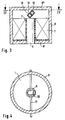
- the magnet coil 1 is accommodated in a practically completely closed housing 8, the cylindrical peripheral wall of which encloses the coil 1 practically without a gap.
- One end wall 8 'of the housing 8 is arranged directly next to the facing end of the coil 1 and is fixedly connected to a rod 6 which passes axially through the coil 1 and which, like the housing 8, is made of soft magnetic material.
- the rod 6 extends up to the top end face of the coil 1 in FIG. 3.
- the other end wall 8 ′′ of the housing 8 is arranged at a distance from the facing end face of the coil 8 and the facing end of the rod 6.
- an extension projecting toward the rod 6 can be arranged on the end wall 8 ′, deviating from the illustration in FIG. 3, the cross section of which can correspond to the cross section of the rod 6.
- the end wall 8 ′′ or the extension arranged thereon on the one hand and the end of the rod 6 facing the end wall 8 ′′ on the other hand form the poles or pole pieces of the electromagnet arrangement, i.e. A magnetic field is generated between the rod 6 and the end wall 8 ′′ or the extension arranged thereon, the strength of which is dependent on the strength of the electrical current passing through the magnet coil 1.
- a shaft 11 with this axis 11 is located by means of the axis 11, which is rotatably mounted in openings in the peripheral wall of the housing 8
- Rotationally connected double-armed lever 10 made of non-magnetizable material, for example plastic, is arranged.
- the arms of the lever 10 are dimensioned such that they cooperate abruptly with the housing end wall 8 ′′ or with the rod 6, such that the lever 10 is able to assume two end positions in which the magnetic north-south direction of the permanent magnet 13 is inclined is aligned with the axis of the magnetic coil 1.
- the permanent magnet 13 and thus the lever 10 then seek to assume one or the other end position. Even when the coil is switched off, the end positions are automatically held due to the magnetic attraction forces which are active between the poles of the permanent magnet 13 and the housing end wall 8 ′′ or the rod 6.
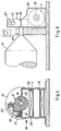
- the magnet coil 1 has a cylindrical magnet coil 1 with a core 20 made of soft magnetic material.
- the magnet coil 1 can be connected to a DC voltage source, not shown, in a manner which can be reversed, so that the coil 1 can be supplied with current in two opposite directions.
- the magnetic north-south direction of the core 20 in FIG. 1 then points from right to left or from left to right.
- Each end of the core 20 is connected to a holding element 23 'or 23' 'which, like the core 20, is made of soft magnetic material.
- the holding elements 23 'and 23'' are designed as sheet metal parts, which essentially consist of a plate arranged at the front end of the magnet coil 1 with a plate plane radial to the coil axis.
- the holding elements 23 'and 23'' have, at their lower edges in FIG. 5, outwardly angled flanges for fastening on an assembly level.
- tabs 24' and 24 '' are arranged in a common plane, which can be offset to the side relative to the axis of the magnetic coil 1 according to FIG. 6.
- the eccentric part 25 consists of non-magnetizable material, for example plastic.
- the eccentric part 25 has a segment 25 ′ in the form of a segment of a circle, by means of which the possible rotational stroke of the eccentric part 25 in cooperation with the tabs 24 ′ and 24 ′′ is limited, i.e. In one end position of the eccentric part 25, the tab 24 'acts as a stop, while the eccentric part 25 strikes the tab 24' 'in its other end position.
- section 25 'of the eccentric part 25 two rod-shaped permanent magnets 27' and 27 '' are embedded, in such a way that on the radial end faces of the section 25 'of the eccentric part 25 poles of the same magnetic polarity - in the example of FIG. 5, the magnetic N -Pole - are arranged.
- poles of the opposite magnetic polarity of the permanent magnets 27 'and 27' ' can abut one another approximately in the radial central plane of the section 25' of the eccentric part 25.
- the eccentric part 25 is connected in a rotationally fixed manner to an organ to be driven, in the example of FIGS. 5 and 6 to a segment roller 12 of a display panel, a shaft bearing 29 common to both parts being arranged axially between the segment roller 12 and the eccentric part 25 .
- the actuator shown in Figures 5 and 6 works as follows: The possible end positions of the eccentric part 25 are secured when the magnet coil 1 is de-energized by the permanent magnets 27 ′ or 27 ′′ interacting with the tabs 24 ′ or 24 ′′.
- the end position shown in FIG. 5 is held by the permanent magnet 27 ', which with its one pole (N pole) faces the tab 24' and tries to attract it. Since the distance between the tab 24 'and the facing pole of the permanent magnet 27' is substantially smaller than the corresponding distance between the tab 24 '' and the facing pole of the permanent magnet 27 '', they are between the permanent magnet 27 'and the tab 24 'acting attractive magnetic forces significantly larger than those between the permanent magnet 27 "and the tab 24".
- the tabs 24 ′ and 24 ′′ form magnetic poles of opposite magnetic polarity, since the holding elements 23 ′ and 23 ′′ consist of magnetizable material and are in a magnetically conductive connection with the core 20 of the magnet coil 1.
- the direction of the electrical current supply to the magnetic coil 1 is selected so that the tab 24 'forms a magnetic south pole, the latter seeks to attract the magnetic north pole facing the permanent magnet 27', while the tab 24 '', which in the specified direction of current supply Magnetic coil 1 has a magnetic north pole forms, repels the facing north pole of the permanent magnet 27 ''. This causes a torque acting on the eccentric part 25 in the direction of the end position shown in FIG. 5.
- the two end positions of the eccentric part 25 can be set by appropriate electrical polarity of the electrical connections of the magnetic coil 1 to the DC voltage source.
- the solenoid 1 can be switched off.
- the permanent magnets 27 'and 27' ' can also be embedded in section 25' of the eccentric part 25 in such a way that they are in the end positions of the eccentric part 25 on the tabs 24 'and 24, respectively '' lie on. As a result, the holding forces securing the end positions of the eccentric part 25 can be increased.
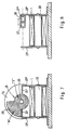
- FIG. 7 differs from the embodiment of FIGS. 5 and 6 only in that the eccentric part 25 is designed as a permanent magnet, the section 25 ′ being the pole of one polarity (N pole) and that of the shaft 26 adjacent area forms the pole of opposite magnetic polarity.
- a slide 30 is arranged between the holding elements 23 'and 23' 'so as to be movable parallel to the axis of the magnetic coil 1, which can be made of plastic, for example.
- two permanent magnets 27 'and 27' ' are embedded in the slider 30, which face each other with their poles of one magnetic polarity, so that the holding elements 23' and 23 '' each face poles of the same magnetic polarity.
- the holding elements 23 'and 23''or tabs 24' and 24 '' formed on them cooperate with the eccentric part 25 or the slide 30 in the manner of stops.
- stops which are connected to the organ driven by the actuator e.g. interact with the segment roller 12.
- the holding elements 23 'and 23' 'or the tabs 24' and 24 '' are not required as mechanical stops.
- Hall generators or other sensors can be arranged which respond to the magnetic field of the permanent magnets in these positions.
- the positions to be set can be maintained with great force even when the electromagnet is de-energized, a greatly increased holding force possibly being possible by energizing the electromagnet, specifically in both positions.
- a short current surge is sufficient to switch between the two positions, i.e. the energy consumption is low.
Landscapes
- Physics & Mathematics (AREA)
- Electromagnetism (AREA)
- Engineering & Computer Science (AREA)
- Power Engineering (AREA)
- Reciprocating, Oscillating Or Vibrating Motors (AREA)
- Electromagnets (AREA)
- Vehicle Body Suspensions (AREA)
- Seal Device For Vehicle (AREA)
- Particle Accelerators (AREA)
- Fluid-Damping Devices (AREA)
- Prostheses (AREA)
Applications Claiming Priority (4)
| Application Number | Priority Date | Filing Date | Title |
|---|---|---|---|
| DE19904020275 DE4020275C2 (de) | 1990-06-26 | 1990-06-26 | Stellenantrieb zur Einstellung von zwei selbsthaltenden Lagen |
| DE4020275 | 1990-06-26 | ||
| DE4027366 | 1990-08-30 | ||
| DE4027366A DE4027366A1 (de) | 1990-06-26 | 1990-08-30 | Stellantrieb zur einstellung von zwei lagen |
Publications (3)
| Publication Number | Publication Date |
|---|---|
| EP0463590A2 true EP0463590A2 (fr) | 1992-01-02 |
| EP0463590A3 EP0463590A3 (en) | 1993-02-24 |
| EP0463590B1 EP0463590B1 (fr) | 1997-08-20 |
Family
ID=25894459
Family Applications (1)
| Application Number | Title | Priority Date | Filing Date |
|---|---|---|---|
| EP91110334A Expired - Lifetime EP0463590B1 (fr) | 1990-06-26 | 1991-06-22 | Dispositif d'entraînement pour réglage de deux positions à auto-maintien |
Country Status (4)
| Country | Link |
|---|---|
| EP (1) | EP0463590B1 (fr) |
| AT (1) | ATE157195T1 (fr) |
| DE (2) | DE4027366A1 (fr) |
| ES (1) | ES2106745T3 (fr) |
Cited By (2)
| Publication number | Priority date | Publication date | Assignee | Title |
|---|---|---|---|---|
| FR2717947A1 (fr) * | 1994-03-25 | 1995-09-29 | Sagem | Actionneur électromagnétique rotatif à débattement angulaire limité. |
| CN112967861A (zh) * | 2021-03-02 | 2021-06-15 | 东莞市粤海磁电科技有限公司 | 一种用于磁铁充磁的自动多极充磁设备 |
Family Cites Families (7)
| Publication number | Priority date | Publication date | Assignee | Title |
|---|---|---|---|---|
| US2632072A (en) * | 1950-03-20 | 1953-03-17 | Floyd L Zellner | Low voltage switch |
| DE1292244B (de) * | 1963-01-31 | 1969-04-10 | Siemens Ag | Elektrisches Schaltgeraet |
| AU1155866A (en) * | 1967-06-22 | 1969-01-09 | Telephone & Electrical Industries Pty. Ltd | Electromechanical bi-stable motive unit |
| CA1132646A (fr) * | 1979-06-05 | 1982-09-28 | Christian C. Petersen | Moteur lineaire |
| DE3520773C1 (de) * | 1985-05-29 | 1989-07-20 | SDS-Relais AG, 8024 Deisenhofen | Elektromagnetisches Relais |
| DE3640188C2 (de) * | 1986-11-25 | 1995-03-23 | Deutsche Aerospace | Stellglied |
| DE3843646C2 (de) * | 1988-12-23 | 1994-05-26 | Spinner Georg | Elektromagnetischer Schalterantrieb |
-
1990
- 1990-08-30 DE DE4027366A patent/DE4027366A1/de not_active Withdrawn
-
1991
- 1991-06-22 DE DE59108827T patent/DE59108827D1/de not_active Expired - Fee Related
- 1991-06-22 EP EP91110334A patent/EP0463590B1/fr not_active Expired - Lifetime
- 1991-06-22 ES ES91110334T patent/ES2106745T3/es not_active Expired - Lifetime
- 1991-06-22 AT AT91110334T patent/ATE157195T1/de active
Cited By (4)
| Publication number | Priority date | Publication date | Assignee | Title |
|---|---|---|---|---|
| FR2717947A1 (fr) * | 1994-03-25 | 1995-09-29 | Sagem | Actionneur électromagnétique rotatif à débattement angulaire limité. |
| US5677659A (en) * | 1994-03-25 | 1997-10-14 | Societe D'applications Generales D'electricite Et De Mecanique-Sagem | Limited angular deflecting type rotary electromagnetic actuator |
| CN112967861A (zh) * | 2021-03-02 | 2021-06-15 | 东莞市粤海磁电科技有限公司 | 一种用于磁铁充磁的自动多极充磁设备 |
| CN112967861B (zh) * | 2021-03-02 | 2022-09-16 | 东莞市粤海磁电科技有限公司 | 一种用于磁铁充磁的自动多极充磁设备 |
Also Published As
| Publication number | Publication date |
|---|---|
| DE4027366A1 (de) | 1992-03-19 |
| ES2106745T3 (es) | 1997-11-16 |
| DE59108827D1 (de) | 1997-09-25 |
| EP0463590B1 (fr) | 1997-08-20 |
| EP0463590A3 (en) | 1993-02-24 |
| ATE157195T1 (de) | 1997-09-15 |
Similar Documents
| Publication | Publication Date | Title |
|---|---|---|
| EP2561523B1 (fr) | Actionneur magnétique bistable | |
| DE68912964T2 (de) | Elektromagnetische Stellantriebe. | |
| DE3315682A1 (de) | Winkelstellglied | |
| EP3091645B1 (fr) | Moteur electrique et circuit electrique | |
| DE1524616C3 (de) | Anzeigevorrichtung | |
| EP3036387A1 (fr) | Serrure de véhicule automobile | |
| WO2021069405A1 (fr) | Dispositif de verrouillage et colonne de direction à dispositif de verrouillage | |
| DE3687690T2 (de) | Verriegelungsdrehmagnet. | |
| DE1589914A1 (de) | Rotierendes,elektromagnetisches Betaetigungselement | |
| DE602004007646T3 (de) | Elektromagnetischer antrieb | |
| DE3612289A1 (de) | Magnetisch betaetigtes stellglied | |
| DE69807784T2 (de) | Elektromagnetische Antriebsvorrichtung mit beweglichem Permanentmagnet | |
| DE102013102276B4 (de) | Verdrehschutz | |
| DE102021209914B3 (de) | Stellantrieb mit einer elektrisch ein- und ausschaltbaren, berührungsfrei arbeitenden magnetischen Rastmomenthemmung zum Halten oder Lösen eines Rotorbechers eines Stellantriebmotors | |
| EP0463590B1 (fr) | Dispositif d'entraînement pour réglage de deux positions à auto-maintien | |
| DE4020275C2 (de) | Stellenantrieb zur Einstellung von zwei selbsthaltenden Lagen | |
| DE2146659C3 (de) | Bistabiler elektromagnetischer Anzeiger | |
| DE4012680A1 (de) | Steuerungsschaltung fuer ein stellglied | |
| EP1897108B1 (fr) | Dispositif de commutation electrique dote d'elements de reglage magnetiques pour un element de commutation | |
| DE3423469A1 (de) | Monostabiler betaetigungsmagnet | |
| DE69509237T2 (de) | Elektromagnetischer drehsteller | |
| DE2853232B1 (de) | Photographischer Kameraverschluss mit elektromagnetisch antreibbaren Blenden- und/oder Verschlusslamellen | |
| DE4409503C2 (de) | Elektromagnetisches Gerät | |
| DE3338602C2 (fr) | ||
| DE2834579C2 (de) | Motor |
Legal Events
| Date | Code | Title | Description |
|---|---|---|---|
| PUAI | Public reference made under article 153(3) epc to a published international application that has entered the european phase |
Free format text: ORIGINAL CODE: 0009012 |
|
| AK | Designated contracting states |
Kind code of ref document: A2 Designated state(s): AT CH DE ES FR GB IT LI SE |
|
| PUAL | Search report despatched |
Free format text: ORIGINAL CODE: 0009013 |
|
| AK | Designated contracting states |
Kind code of ref document: A3 Designated state(s): AT CH DE ES FR GB IT LI SE |
|
| RAP1 | Party data changed (applicant data changed or rights of an application transferred) |
Owner name: LUCAS INDUSTRIES PUBLIC LIMITED COMPANY |
|
| 17P | Request for examination filed |
Effective date: 19930717 |
|
| 17Q | First examination report despatched |
Effective date: 19950609 |
|
| GRAG | Despatch of communication of intention to grant |
Free format text: ORIGINAL CODE: EPIDOS AGRA |
|
| GRAH | Despatch of communication of intention to grant a patent |
Free format text: ORIGINAL CODE: EPIDOS IGRA |
|
| GRAH | Despatch of communication of intention to grant a patent |
Free format text: ORIGINAL CODE: EPIDOS IGRA |
|
| GRAA | (expected) grant |
Free format text: ORIGINAL CODE: 0009210 |
|
| AK | Designated contracting states |
Kind code of ref document: B1 Designated state(s): AT CH DE ES FR GB IT LI SE |
|
| REF | Corresponds to: |
Ref document number: 157195 Country of ref document: AT Date of ref document: 19970915 Kind code of ref document: T |
|
| REG | Reference to a national code |
Ref country code: CH Ref legal event code: EP |
|
| REF | Corresponds to: |
Ref document number: 59108827 Country of ref document: DE Date of ref document: 19970925 |
|
| ET | Fr: translation filed | ||
| REG | Reference to a national code |
Ref country code: ES Ref legal event code: FG2A Ref document number: 2106745 Country of ref document: ES Kind code of ref document: T3 |
|
| GBT | Gb: translation of ep patent filed (gb section 77(6)(a)/1977) |
Effective date: 19971029 |
|
| PG25 | Lapsed in a contracting state [announced via postgrant information from national office to epo] |
Ref country code: SE Effective date: 19971120 |
|
| PG25 | Lapsed in a contracting state [announced via postgrant information from national office to epo] |
Ref country code: AT Free format text: LAPSE BECAUSE OF NON-PAYMENT OF DUE FEES Effective date: 19980622 |
|
| PG25 | Lapsed in a contracting state [announced via postgrant information from national office to epo] |
Ref country code: ES Free format text: LAPSE BECAUSE OF NON-PAYMENT OF DUE FEES Effective date: 19980623 |
|
| PLBE | No opposition filed within time limit |
Free format text: ORIGINAL CODE: 0009261 |
|
| STAA | Information on the status of an ep patent application or granted ep patent |
Free format text: STATUS: NO OPPOSITION FILED WITHIN TIME LIMIT |
|
| PG25 | Lapsed in a contracting state [announced via postgrant information from national office to epo] |
Ref country code: LI Free format text: LAPSE BECAUSE OF NON-PAYMENT OF DUE FEES Effective date: 19980630 Ref country code: CH Free format text: LAPSE BECAUSE OF NON-PAYMENT OF DUE FEES Effective date: 19980630 |
|
| 26N | No opposition filed | ||
| REG | Reference to a national code |
Ref country code: CH Ref legal event code: PL |
|
| REG | Reference to a national code |
Ref country code: FR Ref legal event code: TQ |
|
| REG | Reference to a national code |
Ref country code: GB Ref legal event code: 732E |
|
| REG | Reference to a national code |
Ref country code: GB Ref legal event code: IF02 |
|
| REG | Reference to a national code |
Ref country code: ES Ref legal event code: FD2A Effective date: 19990712 |
|
| PGFP | Annual fee paid to national office [announced via postgrant information from national office to epo] |
Ref country code: FR Payment date: 20050621 Year of fee payment: 15 |
|
| PG25 | Lapsed in a contracting state [announced via postgrant information from national office to epo] |
Ref country code: IT Free format text: LAPSE BECAUSE OF NON-PAYMENT OF DUE FEES;WARNING: LAPSES OF ITALIAN PATENTS WITH EFFECTIVE DATE BEFORE 2007 MAY HAVE OCCURRED AT ANY TIME BEFORE 2007. THE CORRECT EFFECTIVE DATE MAY BE DIFFERENT FROM THE ONE RECORDED. Effective date: 20050622 |
|
| PGFP | Annual fee paid to national office [announced via postgrant information from national office to epo] |
Ref country code: DE Payment date: 20050719 Year of fee payment: 15 |
|
| PGFP | Annual fee paid to national office [announced via postgrant information from national office to epo] |
Ref country code: GB Payment date: 20060721 Year of fee payment: 16 |
|
| PG25 | Lapsed in a contracting state [announced via postgrant information from national office to epo] |
Ref country code: DE Free format text: LAPSE BECAUSE OF NON-PAYMENT OF DUE FEES Effective date: 20070103 |
|
| REG | Reference to a national code |
Ref country code: FR Ref legal event code: ST Effective date: 20070228 |
|
| GBPC | Gb: european patent ceased through non-payment of renewal fee |
Effective date: 20070622 |
|
| PG25 | Lapsed in a contracting state [announced via postgrant information from national office to epo] |
Ref country code: FR Free format text: LAPSE BECAUSE OF NON-PAYMENT OF DUE FEES Effective date: 20060630 |
|
| PG25 | Lapsed in a contracting state [announced via postgrant information from national office to epo] |
Ref country code: GB Free format text: LAPSE BECAUSE OF NON-PAYMENT OF DUE FEES Effective date: 20070622 |