EP0463637A2 - Système d'aération de faîtage - Google Patents
Système d'aération de faîtage Download PDFInfo
- Publication number
- EP0463637A2 EP0463637A2 EP91114024A EP91114024A EP0463637A2 EP 0463637 A2 EP0463637 A2 EP 0463637A2 EP 91114024 A EP91114024 A EP 91114024A EP 91114024 A EP91114024 A EP 91114024A EP 0463637 A2 EP0463637 A2 EP 0463637A2
- Authority
- EP
- European Patent Office
- Prior art keywords
- ridge
- inflow
- elements
- fan
- ventilation system
- Prior art date
- Legal status (The legal status is an assumption and is not a legal conclusion. Google has not performed a legal analysis and makes no representation as to the accuracy of the status listed.)
- Granted
Links
Images
Classifications
-
- E—FIXED CONSTRUCTIONS
- E04—BUILDING
- E04D—ROOF COVERINGS; SKY-LIGHTS; GUTTERS; ROOF-WORKING TOOLS
- E04D13/00—Special arrangements or devices in connection with roof coverings; Protection against birds; Roof drainage ; Sky-lights
- E04D13/17—Ventilation of roof coverings not otherwise provided for
- E04D13/174—Ventilation of roof coverings not otherwise provided for on the ridge of the roof
Definitions
- the invention relates to a ridge ventilation system, consisting of fan ridge caps which are arranged one behind the other in the ridge longitudinal direction and can be fixed to a ridge batten and extend as far as ridge connecting tiles, as well as ridge tiles which overlap them.
- a ridge ventilation system of this type is known from DE-PS 33 17 291.
- the object of the invention is to design such a ridge ventilation system in such a way that the best possible air circulation and, in particular under practically all occurring inflow conditions, a pronounced vacuum generation and thus the best possible ridge ventilation is obtained through the design and the interaction of the fan ridge cap and the ridge tile.
- inflow elements having air separation edges on the outside or inside of the roof are arranged and fixed by means of angled areas, projections or hooking noses or the like under the brick or directly connected or coupled to the respective cover cap.
- the flow impingement elements close to the first terminal bricks preferably an angle in the range of 80 to 110 o a, said flow impingement elements may be planar or at least formed angled toward in its free end region to the ridge, said lead these bends to form additional flow separation edges.
- the inflow elements are preferably fastened within the ridge tiles via mutually spaced hanging elements and the like, or are fixed to ridge or ridge sealing elements or are formed or connected in one piece to them.
- the inflow elements are essentially U-shaped in cross-section, the inner leg forming the fixing leg and the outer leg forming the inflow surface and the central region located between the two legs serving to accommodate the ridge tile edge regions.
- the inflow element which is U-shaped in cross section
- a fan ridge cap it being possible for an overall one-piece embodiment to be provided or to design the fan ridge cap and inflow element to be couplable.
- the detachable embodiment has the particular advantage that a specific configuration of a fan ridge cap can be combined with different inflow elements in order to achieve the desired optimum in terms of construction and function.
- the coupling of the fan ridge cap and the inflow element can take place in various ways, either in the form of a fixed connection by welding, gluing, riveting and the like, or in the form of a detachable connection, in particular sliding guides, plug-in or hook-in connections, push-button connections or Velcro connections own.
- the inflow elements are arranged on the inside of the roof and in particular are designed such that they are fixed to the fan cap.
- These inflow elements can either extend continuously over the entire length of the fan ridge cap or consist of individual sections which are each assigned to an air passage opening.
- the inflow elements have an angled shape in cross section and have at least one leg that at least partially covers the respectively assigned air passage opening at a distance. This covering is expediently chosen such that the respective air passage opening is covered at least half in plan view. This protects the air outlet openings from undesired air flows directed into the roof interior, but it is achieved above all that vacuum effects in a pronounced form are also produced directly adjacent to these air outlet openings, and thus a decisive promotion of the vacuum formation in the ridge area takes place, which in turn is essential that the desired roof ventilation is obtained in the form of a flow directed from the inside out.
- inflow elements located on the outside of the roof and inflow elements on the inside of the roof or formed on fan ridge caps can achieve an extremely surprising effect in that a flow directed outwards from the interior of the roof is achieved both on the windward side and on the leeward side, since the formation of negative pressure in the ridge area is promoted by the spoiler functions that even with a small flow around the ridge area and much more pronounced with a strong flow around the ridge area, very pronounced suction effects occur at all air passage openings leading to the roof interior.
- a favorable effect on this desired flow pattern is that the flow on its way from the roof interior to the outside is only exposed to a minimum of deflections due to the formation of the fan ridge caps and thus only slight pressure losses occur.
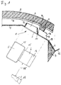
- the general reference numeral 1 denotes a fan ridge cap, which consists of plastic stiffness that can be predetermined and comprises a ridge fastening area 2, also known as a nail bar, a central area 3 and an edge area 4. The individual areas merge into one another via kinks.
- the fan ridge cap 1 shown is of course only one half of an overall cap, it being possible for an overall cap to be formed in one piece.
- air passage openings 5 are formed directly adjacent to the ridge fastening area 2. These air passage openings 5, which are preferably rectangular in cross section, are formed by protuberances 12 open on the ridge tile side, the height of which is somewhat less than the height of bulges 6 which are also located in the central region 3 and on which the ridge tiles 8 are preferably supported by in particular continuous longitudinal webs 9.
- the ridge tile 8 can also be equipped with cross stiffening webs 10.
- the protuberances 12 and the bulges 6 are spaced apart from one another and, if necessary, connected to one another by a stiffening web 11 of comparatively low height.
- the bulges 6 When viewed in the longitudinal direction of the fan ridge cap 1, the bulges 6 have a somewhat smaller width than the air passage openings 5, and they are expediently arranged in the center with respect to these air passage openings 5.
- the relatively steep surface 14 of the bulges 6 on the edge region forms an inflow surface which has a spoiler function, flow stall effects occurring at the boundary edges of this inflow surface 14, which contribute to the formation of negative pressure and promote and promote an inside-out flow through the through openings 5.
- Defined flow conditions are also achieved in that the air passage openings 5 are located entirely within the area delimited by the ridge tile webs 9.
- the kink 13 between the central region 3 and the edge region 4 of the fan ridge cap 1 is designed such that sufficient force transmission from the bulges 6 to this edge region 4 is possible in order to fit this edge region 4 tightly or an elastic one attached to the underside of this edge region 4 Ensure molded body 7 on the respective ridge connection tiles.
- the elastic molded body 7 which may be used can have a triangular or parallelogram-like shape in cross-section, the cross-sectional shape being selected as a function of the type of ridge connecting tile.
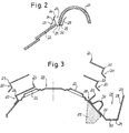
- Fig. 2 shows schematically the arrangement of an inflow element 20 in the area between the ridge tiles 21 and the ridge connection tiles 22.
- the inflow element is approximately U-shaped in cross section, the inner leg 27 serving as a fastening leg and in a manner not shown can be connected to existing components or components of the ridge construction located within the ridge tile 21.
- the outer leg 28 represents the actual inflow surface.
- the two legs 27, 28 are connected to one another via a leg 29 forming the bottom, 21 air passage openings 25 being present between this leg 29 and the ridge tiles.
- Support elements 32 for the fan ridge tiles 21 can be formed on the connecting leg 29.
- measures in the form of holes, slots and the like have been taken to allow water to drain from the channel-like structure.
- the outer leg 28 forming the inflow surface can be provided at its free end with an angled portion 26, which is inclined differently with respect to the inflow surface, as was indicated by the broken line in FIG. 2. In this way, particularly favorable stall conditions can be created.
- the inflow element 20 can be equipped with attachment elements 24 in the form of a web, by means of which elements are supported on the ridge connection tiles.
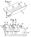
- the sectional view according to FIG. 3 shows different variants of a possible combination of inflow elements with fan ridge caps.
- inflow elements 20 are shown, which are assigned to a ventilation opening 25, which is attached to the top of a protuberance.
- the inflow elements consist of angled parts, which extend in the longitudinal direction of the fan ridge cap 20, are fastened directly adjacent to the ventilation openings 25 and extend over the ventilation openings 25, the distance between the ventilation opening 25 and the overlapping leg of the inflow element being freely selectable and the optimal distance can be determined in particular by appropriate flow tests.
- inflow elements have tear-off edges 23, which in operation are the cause of a negative pressure generation, which in turn leads to the fact that a flow directed outward from the roof interior through the openings 25 can be achieved.
- a variant of a fan ridge cap is shown, which is equipped in the edge area with bumps 31 for supporting ridge tiles and which can be equipped with a sealing element 35 on the underside of the edge area.
- an inflow element 20 with an air separation edge 23 is provided between the ventilation openings 25 and the bumps 31, an inflow element 20 with an air separation edge 23 is provided.
- This inflow element has an L-shaped shape in cross section, one leg forming the inflow surface and the other leg serving for fastening purposes.
- inflow elements located within the ridge tiles and directly assigned to the ventilation openings 25 can also be used, which can be coupled or fixedly connected to the fan ridge cap 33.
- These inflow elements 20 have an approximately U-shaped structure in cross section, the inner fastening leg 27 being connected to the fan ridge cap 33 and the outer leg 28 forming the inflow surface with tear-off edge 23. Water passage openings 30 are formed in the middle leg 29.
- FIG. 4 shows the combination of a fan ridge cap 33 with ridge tile support elements 31 with an inflow element 20 which is approximately U-shaped in cross section, the associated ridge tiles engaging in the U profile and the outside inflow surface having the tear-off edge 23 via the outside of the roof protrudes.
- This inflow element 20 can be molded directly onto the fan ridge cap 33, but expediently it is a separate part that can be glued, welded, riveted or otherwise permanently connected to the fan ridge cap 33 as required. It is also possible to use the support elements 31 for coupling purposes, in which case the inner leg of the inflow element 20 is made longer and provided with corresponding openings through which the support elements 31 can pass.
- FIG. 5 shows a perspective partial illustration of an embodiment with inflow elements 20 located within the ridge tile, which, starting from a common fastening leg 36 which extends over the length of the fan ridge cap 33, each extend at least in regions over the associated air passage openings 25 in the fan ridge cap 33.
- inflow elements 20 located within the ridge tile, which, starting from a common fastening leg 36 which extends over the length of the fan ridge cap 33, each extend at least in regions over the associated air passage openings 25 in the fan ridge cap 33.
- the inflow elements simultaneously form protective elements against driving rain and flying snow and make a decisive contribution to the formation of negative pressure in the ridge area.
Landscapes
- Engineering & Computer Science (AREA)
- Architecture (AREA)
- Civil Engineering (AREA)
- Structural Engineering (AREA)
- Roof Covering Using Slabs Or Stiff Sheets (AREA)
- Building Environments (AREA)
- Glass Compositions (AREA)
- Farming Of Fish And Shellfish (AREA)
- Nonmetallic Welding Materials (AREA)
- Transition And Organic Metals Composition Catalysts For Addition Polymerization (AREA)
- Medicines That Contain Protein Lipid Enzymes And Other Medicines (AREA)
Applications Claiming Priority (5)
| Application Number | Priority Date | Filing Date | Title |
|---|---|---|---|
| DE3812305 | 1988-04-13 | ||
| DE19883812305 DE3812305C2 (de) | 1988-04-13 | 1988-04-13 | Firstentlüftungssystem |
| DE3813094 | 1988-04-19 | ||
| DE19883813094 DE3813094C2 (de) | 1988-04-19 | 1988-04-19 | Lüfterfirstkappe zur Hinterlüftung von Dächern |
| EP89106637A EP0337461B1 (fr) | 1988-04-13 | 1989-04-13 | Système d'aération de faîtage |
Related Parent Applications (1)
| Application Number | Title | Priority Date | Filing Date |
|---|---|---|---|
| EP89106637.5 Division | 1989-04-13 |
Publications (3)
| Publication Number | Publication Date |
|---|---|
| EP0463637A2 true EP0463637A2 (fr) | 1992-01-02 |
| EP0463637A3 EP0463637A3 (en) | 1992-10-28 |
| EP0463637B1 EP0463637B1 (fr) | 1994-10-26 |
Family
ID=25866941
Family Applications (2)
| Application Number | Title | Priority Date | Filing Date |
|---|---|---|---|
| EP89106637A Expired - Lifetime EP0337461B1 (fr) | 1988-04-13 | 1989-04-13 | Système d'aération de faîtage |
| EP91114024A Expired - Lifetime EP0463637B1 (fr) | 1988-04-13 | 1989-04-13 | Système d'aération de faîtage |
Family Applications Before (1)
| Application Number | Title | Priority Date | Filing Date |
|---|---|---|---|
| EP89106637A Expired - Lifetime EP0337461B1 (fr) | 1988-04-13 | 1989-04-13 | Système d'aération de faîtage |
Country Status (4)
| Country | Link |
|---|---|
| EP (2) | EP0337461B1 (fr) |
| AT (1) | ATE113333T1 (fr) |
| DE (2) | DE58908573D1 (fr) |
| ES (1) | ES2063420T3 (fr) |
Cited By (1)
| Publication number | Priority date | Publication date | Assignee | Title |
|---|---|---|---|---|
| EP0657598A1 (fr) * | 1993-12-10 | 1995-06-14 | GEHRING, Manfred, Dr. | Recouvrement de faîte et/ou d'arête de toits ainsi que procédé pour la réalisation de recouvrement de faite et/ou d'arête |
Families Citing this family (3)
| Publication number | Priority date | Publication date | Assignee | Title |
|---|---|---|---|---|
| DE59003097D1 (de) * | 1989-02-02 | 1993-11-25 | Norm Amc Ag | Vorrichtung zur Hinterlüftung von Dächern. |
| ATE78074T1 (de) * | 1989-05-05 | 1992-07-15 | Kloeber Fa Hans | Firstlueftungselement. |
| DE3933972A1 (de) * | 1989-10-11 | 1991-04-18 | Gehring Gmbh Maschf | Firstentlueftung |
Family Cites Families (14)
| Publication number | Priority date | Publication date | Assignee | Title |
|---|---|---|---|---|
| US3326113A (en) * | 1964-09-28 | 1967-06-20 | Smith | Roof ridge ventilator |
| DE2356782A1 (de) * | 1973-11-14 | 1975-05-28 | Wilhelm Helling | Vorrichtung zum entlueften von pfannengedeckten daechern |
| DE3313875A1 (de) * | 1982-05-22 | 1983-11-24 | Oskar 4354 Datteln Fleck | Hohles first- oder gratabdeckelement mit lueftungsoeffnungen |
| GB2123050B (en) * | 1982-06-25 | 1986-01-29 | Marley Roof Tile | Roof ridge capping system |
| DE3317291C1 (de) * | 1983-05-11 | 1984-08-30 | Erlus Baustoffwerke Ag, 8301 Neufahrn | Firstziegel für eine Firstentlüftung |
| DE3511798A1 (de) * | 1984-05-30 | 1985-12-05 | Alfons 5758 Fröndenberg Knoche | Firstentlueftung an daechern |
| US4554862A (en) * | 1984-06-21 | 1985-11-26 | Air Vent Inc. | Roof ridge ventilator for retarding microbe growth in shingle roofs |
| DE8527095U1 (de) * | 1985-09-21 | 1987-09-17 | Gehring, Manfred, 7290 Freudenstadt | Dichtungsstreifen für First- und Gratabdeckungen |
| DE3615015C1 (en) * | 1986-05-02 | 1987-12-03 | Alfons Knoche | Ridge-venting element |
| DE8612822U1 (de) * | 1986-05-10 | 1986-08-21 | Fleck, Oskar, 4354 Datteln | Standverbreiterungselement für die Ränder von Firstziegeln |
| DE8713110U1 (de) * | 1987-09-30 | 1988-01-21 | Fleck, Oskar, 4354 Datteln | Gewölbtes Firstabdichtungs- und -belüftungselement |
| DE8712892U1 (de) * | 1987-09-24 | 1987-12-17 | Norm A.M.C. Ag, Erstfeld | Lüfterkappe für First- und Gratabdeckungen |
| DE3806683A1 (de) * | 1988-03-02 | 1989-09-14 | Kloeber Johannes | Firststreifen |
| DE3825348C2 (de) * | 1988-07-26 | 1996-07-18 | Norm Amc Ag | Vorrichtung zur Hinterlüftung von Dächern |
-
1989
- 1989-04-13 EP EP89106637A patent/EP0337461B1/fr not_active Expired - Lifetime
- 1989-04-13 DE DE58908573T patent/DE58908573D1/de not_active Expired - Fee Related
- 1989-04-13 AT AT91114024T patent/ATE113333T1/de not_active IP Right Cessation
- 1989-04-13 DE DE8989106637T patent/DE58902591D1/de not_active Expired - Fee Related
- 1989-04-13 ES ES91114024T patent/ES2063420T3/es not_active Expired - Lifetime
- 1989-04-13 EP EP91114024A patent/EP0463637B1/fr not_active Expired - Lifetime
Cited By (1)
| Publication number | Priority date | Publication date | Assignee | Title |
|---|---|---|---|---|
| EP0657598A1 (fr) * | 1993-12-10 | 1995-06-14 | GEHRING, Manfred, Dr. | Recouvrement de faîte et/ou d'arête de toits ainsi que procédé pour la réalisation de recouvrement de faite et/ou d'arête |
Also Published As
| Publication number | Publication date |
|---|---|
| EP0463637A3 (en) | 1992-10-28 |
| ATE113333T1 (de) | 1994-11-15 |
| EP0337461B1 (fr) | 1992-11-04 |
| ES2063420T3 (es) | 1995-01-01 |
| DE58908573D1 (de) | 1994-12-01 |
| EP0463637B1 (fr) | 1994-10-26 |
| DE58902591D1 (en) | 1992-12-10 |
| EP0337461A1 (fr) | 1989-10-18 |
Similar Documents
| Publication | Publication Date | Title |
|---|---|---|
| EP0263284B1 (fr) | Plaque de toiture | |
| DE10200673B4 (de) | Kraftfahrzeug-Luftfilter | |
| EP0364680B1 (fr) | Elément de couverture de toiture | |
| DE3214876A1 (de) | Wasserfuehrungskanal fuer kraftwagen | |
| DE10336664A1 (de) | Heckflügel für ein Kraftfahrzeug | |
| DE3023083C2 (de) | Firstentlüftung an Dächern | |
| EP0288020B1 (fr) | Poutre faîtière avec élément couvrant d'étanchéité et d'aération de faîtage | |
| EP0463637B1 (fr) | Système d'aération de faîtage | |
| DE8019939U1 (de) | Luftverteileinrichtung insbesondere fuer uebersaettigte luft | |
| DE3813094C2 (de) | Lüfterfirstkappe zur Hinterlüftung von Dächern | |
| DE2822376A1 (de) | Tropfenabscheider | |
| DE3021202C2 (de) | Vorrichtung zum Berieseln von Rieselplatten mit abzukühlendem Kühlwasser | |
| DE2417726A1 (de) | Frontlenkerfahrerhaus von nutzkraftwagen | |
| DE3812305C2 (de) | Firstentlüftungssystem | |
| DE4441296C1 (de) | Universallüfter mit plissierten Seitenteilen in gespritzter Ausführung | |
| DE3643738C1 (en) | Roof wind deflector made of plastic | |
| EP1013845B1 (fr) | Elément de faíte ou d'arête de toit | |
| EP0476531B1 (fr) | Closoir de ventilation pour faîte de toiture | |
| EP0063218A2 (fr) | Tuile avec ouverture de ventilation | |
| DE8003708U1 (de) | Kondensatabscheider fuer einen kuehler | |
| DE9007472U1 (de) | Mit Durchfallschlitzen ausgestatteter Stallrost | |
| DE8402274U1 (de) | Fassadenplatte aus kunststoff | |
| DE3844902C2 (de) | Lüfterkappe zur Hinterlüftung von Dächern im First- oder Gratbereich | |
| DE19728532B4 (de) | Selbsttragende Fahrzeugkarosserie | |
| DE2018948C3 (de) | Dachlüfter |
Legal Events
| Date | Code | Title | Description |
|---|---|---|---|
| PUAI | Public reference made under article 153(3) epc to a published international application that has entered the european phase |
Free format text: ORIGINAL CODE: 0009012 |
|
| AC | Divisional application: reference to earlier application |
Ref document number: 337461 Country of ref document: EP |
|
| AK | Designated contracting states |
Kind code of ref document: A2 Designated state(s): AT BE CH DE ES FR GB GR IT LI LU NL SE |
|
| PUAL | Search report despatched |
Free format text: ORIGINAL CODE: 0009013 |
|
| AK | Designated contracting states |
Kind code of ref document: A3 Designated state(s): AT BE CH DE ES FR GB GR IT LI LU NL SE |
|
| 17P | Request for examination filed |
Effective date: 19921230 |
|
| 17Q | First examination report despatched |
Effective date: 19940118 |
|
| GRAA | (expected) grant |
Free format text: ORIGINAL CODE: 0009210 |
|
| AC | Divisional application: reference to earlier application |
Ref document number: 337461 Country of ref document: EP |
|
| AK | Designated contracting states |
Kind code of ref document: B1 Designated state(s): AT BE CH DE ES FR GB GR IT LI LU NL SE |
|
| REF | Corresponds to: |
Ref document number: 113333 Country of ref document: AT Date of ref document: 19941115 Kind code of ref document: T |
|
| ITF | It: translation for a ep patent filed | ||
| REF | Corresponds to: |
Ref document number: 58908573 Country of ref document: DE Date of ref document: 19941201 |
|
| GBT | Gb: translation of ep patent filed (gb section 77(6)(a)/1977) |
Effective date: 19941103 |
|
| ET | Fr: translation filed | ||
| REG | Reference to a national code |
Ref country code: GR Ref legal event code: FG4A Free format text: 3013783 |
|
| REG | Reference to a national code |
Ref country code: ES Ref legal event code: FG2A Ref document number: 2063420 Country of ref document: ES Kind code of ref document: T3 |
|
| EAL | Se: european patent in force in sweden |
Ref document number: 91114024.2 |
|
| PLBE | No opposition filed within time limit |
Free format text: ORIGINAL CODE: 0009261 |
|
| STAA | Information on the status of an ep patent application or granted ep patent |
Free format text: STATUS: NO OPPOSITION FILED WITHIN TIME LIMIT |
|
| 26N | No opposition filed | ||
| REG | Reference to a national code |
Ref country code: GB Ref legal event code: 732E |
|
| REG | Reference to a national code |
Ref country code: CH Ref legal event code: PUE Owner name: NORM A.M.C. AG TRANSFER- SCHEFFLER GMBH & CO. KG |
|
| REG | Reference to a national code |
Ref country code: FR Ref legal event code: TP |
|
| NLS | Nl: assignments of ep-patents |
Owner name: SCHEFFLER GMBH & CO. KG |
|
| REG | Reference to a national code |
Ref country code: GB Ref legal event code: IF02 |
|
| PGFP | Annual fee paid to national office [announced via postgrant information from national office to epo] |
Ref country code: CH Payment date: 20020319 Year of fee payment: 14 |
|
| PGFP | Annual fee paid to national office [announced via postgrant information from national office to epo] |
Ref country code: SE Payment date: 20020327 Year of fee payment: 14 |
|
| PGFP | Annual fee paid to national office [announced via postgrant information from national office to epo] |
Ref country code: NL Payment date: 20020328 Year of fee payment: 14 Ref country code: AT Payment date: 20020328 Year of fee payment: 14 |
|
| PGFP | Annual fee paid to national office [announced via postgrant information from national office to epo] |
Ref country code: GR Payment date: 20020329 Year of fee payment: 14 |
|
| PGFP | Annual fee paid to national office [announced via postgrant information from national office to epo] |
Ref country code: GB Payment date: 20020402 Year of fee payment: 14 |
|
| PGFP | Annual fee paid to national office [announced via postgrant information from national office to epo] |
Ref country code: LU Payment date: 20020404 Year of fee payment: 14 |
|
| PGFP | Annual fee paid to national office [announced via postgrant information from national office to epo] |
Ref country code: BE Payment date: 20020412 Year of fee payment: 14 |
|
| PGFP | Annual fee paid to national office [announced via postgrant information from national office to epo] |
Ref country code: FR Payment date: 20020416 Year of fee payment: 14 |
|
| PGFP | Annual fee paid to national office [announced via postgrant information from national office to epo] |
Ref country code: ES Payment date: 20020418 Year of fee payment: 14 |
|
| PGFP | Annual fee paid to national office [announced via postgrant information from national office to epo] |
Ref country code: DE Payment date: 20020626 Year of fee payment: 14 |
|
| PG25 | Lapsed in a contracting state [announced via postgrant information from national office to epo] |
Ref country code: LU Free format text: LAPSE BECAUSE OF NON-PAYMENT OF DUE FEES Effective date: 20030413 Ref country code: GB Free format text: LAPSE BECAUSE OF NON-PAYMENT OF DUE FEES Effective date: 20030413 Ref country code: AT Free format text: LAPSE BECAUSE OF NON-PAYMENT OF DUE FEES Effective date: 20030413 |
|
| PG25 | Lapsed in a contracting state [announced via postgrant information from national office to epo] |
Ref country code: SE Free format text: LAPSE BECAUSE OF NON-PAYMENT OF DUE FEES Effective date: 20030414 Ref country code: ES Free format text: LAPSE BECAUSE OF NON-PAYMENT OF DUE FEES Effective date: 20030414 |
|
| PG25 | Lapsed in a contracting state [announced via postgrant information from national office to epo] |
Ref country code: LI Free format text: LAPSE BECAUSE OF NON-PAYMENT OF DUE FEES Effective date: 20030430 Ref country code: CH Free format text: LAPSE BECAUSE OF NON-PAYMENT OF DUE FEES Effective date: 20030430 Ref country code: BE Free format text: LAPSE BECAUSE OF NON-PAYMENT OF DUE FEES Effective date: 20030430 |
|
| BERE | Be: lapsed |
Owner name: *SCHEFFLER G.M.B.H & CO. K.G. Effective date: 20030430 |
|
| PG25 | Lapsed in a contracting state [announced via postgrant information from national office to epo] |
Ref country code: NL Free format text: LAPSE BECAUSE OF NON-PAYMENT OF DUE FEES Effective date: 20031101 Ref country code: DE Free format text: LAPSE BECAUSE OF NON-PAYMENT OF DUE FEES Effective date: 20031101 |
|
| PG25 | Lapsed in a contracting state [announced via postgrant information from national office to epo] |
Ref country code: GR Free format text: LAPSE BECAUSE OF NON-PAYMENT OF DUE FEES Effective date: 20031104 |
|
| NLV4 | Nl: lapsed or anulled due to non-payment of the annual fee |
Effective date: 20031101 |
|
| EUG | Se: european patent has lapsed | ||
| GBPC | Gb: european patent ceased through non-payment of renewal fee |
Effective date: 20030413 |
|
| REG | Reference to a national code |
Ref country code: CH Ref legal event code: PL |
|
| PG25 | Lapsed in a contracting state [announced via postgrant information from national office to epo] |
Ref country code: FR Free format text: LAPSE BECAUSE OF NON-PAYMENT OF DUE FEES Effective date: 20031231 |
|
| REG | Reference to a national code |
Ref country code: FR Ref legal event code: ST |
|
| REG | Reference to a national code |
Ref country code: ES Ref legal event code: FD2A Effective date: 20030414 |
|
| PG25 | Lapsed in a contracting state [announced via postgrant information from national office to epo] |
Ref country code: IT Free format text: LAPSE BECAUSE OF NON-PAYMENT OF DUE FEES;WARNING: LAPSES OF ITALIAN PATENTS WITH EFFECTIVE DATE BEFORE 2007 MAY HAVE OCCURRED AT ANY TIME BEFORE 2007. THE CORRECT EFFECTIVE DATE MAY BE DIFFERENT FROM THE ONE RECORDED. Effective date: 20050413 |