EP0463697B1 - Lüftungsluke - Google Patents
Lüftungsluke Download PDFInfo
- Publication number
- EP0463697B1 EP0463697B1 EP91201574A EP91201574A EP0463697B1 EP 0463697 B1 EP0463697 B1 EP 0463697B1 EP 91201574 A EP91201574 A EP 91201574A EP 91201574 A EP91201574 A EP 91201574A EP 0463697 B1 EP0463697 B1 EP 0463697B1
- Authority
- EP
- European Patent Office
- Prior art keywords
- pull rod
- closing members
- closing
- hinge
- opening
- Prior art date
- Legal status (The legal status is an assumption and is not a legal conclusion. Google has not performed a legal analysis and makes no representation as to the accuracy of the status listed.)
- Expired - Lifetime
Links
- 238000010276 construction Methods 0.000 description 3
- 238000005192 partition Methods 0.000 description 3
- XLYOFNOQVPJJNP-UHFFFAOYSA-N water Substances O XLYOFNOQVPJJNP-UHFFFAOYSA-N 0.000 description 3
- 238000007789 sealing Methods 0.000 description 1
- 238000003756 stirring Methods 0.000 description 1
- 238000009423 ventilation Methods 0.000 description 1
Images

Classifications
-
- F—MECHANICAL ENGINEERING; LIGHTING; HEATING; WEAPONS; BLASTING
- F24—HEATING; RANGES; VENTILATING
- F24F—AIR-CONDITIONING; AIR-HUMIDIFICATION; VENTILATION; USE OF AIR CURRENTS FOR SCREENING
- F24F13/00—Details common to, or for air-conditioning, air-humidification, ventilation or use of air currents for screening
- F24F13/08—Air-flow control members, e.g. louvres, grilles, flaps or guide plates
- F24F13/10—Air-flow control members, e.g. louvres, grilles, flaps or guide plates movable, e.g. dampers
- F24F13/14—Air-flow control members, e.g. louvres, grilles, flaps or guide plates movable, e.g. dampers built up of tilting members, e.g. louvre
- F24F13/15—Air-flow control members, e.g. louvres, grilles, flaps or guide plates movable, e.g. dampers built up of tilting members, e.g. louvre with parallel simultaneously tiltable lamellae
-
- E—FIXED CONSTRUCTIONS
- E04—BUILDING
- E04B—GENERAL BUILDING CONSTRUCTIONS; WALLS, e.g. PARTITIONS; ROOFS; FLOORS; CEILINGS; INSULATION OR OTHER PROTECTION OF BUILDINGS
- E04B7/00—Roofs; Roof construction with regard to insulation
- E04B7/16—Roof structures with movable roof parts
- E04B7/163—Roof structures with movable roof parts characterised by a pivoting movement of the movable roof parts
-
- F—MECHANICAL ENGINEERING; LIGHTING; HEATING; WEAPONS; BLASTING
- F24—HEATING; RANGES; VENTILATING
- F24F—AIR-CONDITIONING; AIR-HUMIDIFICATION; VENTILATION; USE OF AIR CURRENTS FOR SCREENING
- F24F7/00—Ventilation
- F24F7/02—Roof ventilation
Definitions
- This invention relates to a ventilating hatch comprising a framework surrounding the hatch opening, the longitudinal sides of the framework following a generally arcuate curve in the same direction relative to their axes, and which hatch opening so curved can be closed off with a hinged closing cover cooperating therewith.
- a ventilating hatch of this type is known and commercially available, and used inter alia on factory roofs as a so-called "light lane", for supplying the space therebelow with light as well as for ventilation, by hinging the closing cover into the open position.
- a drawback of such a hinging curved closing cover is that the curved surface has a considerable catch of wind when the closing cover is in the open position, there being a very substantial chance that the closing cover is torn off by gusts of wind, with all unpleasant consequences thereof.
- Another solution could be to divide the closing cover into a plurality of separate closing members, with each closing member being hinged relative to the short side of the hatch opening. It has been experimentally demonstrated that, at least when an upright edge is provided at the longitudinal ends, this solution prevents the wind from being deflected towards the space below and allows it to accommodate to the curved surface, i.e. to pass over the opened closing members.
- the problem involved here is opening and closing all closing members simultaneously, as the closing members are not in one straight line.
- a possibility is to use a flexible rope which interconnects all closing members. This means, however, that for opening the closing members the rope must be pulled at one end, and for closing them it must be pulled at the other. Apart from the aesthetic aspect, such a construction is clumsy and requires additional provisions, certainly if the closing members are to be operated by remote control, for instance hydraulically.
- the object of the invention is to overcome the drawbacks and to provide a curved ventilating hatch which, in combination with a closing cover divided into a plurality of separate closing members and a common rigid connection between the closing members, permits opening and closing of the closing members in one operation of the rigid connection, without torsion arising.
- the closing cover consists of a plurality of separate closing members which are each hinged relative to a longitudinal end thereof about a corresponding hinge pin coupled to the longitudinal sides of the framework, said hinge pins extending parallel to the transverse side of the framework, and that, for opening and closing each of the closing members, there is provided a common pull rod whose axis follows a substantially arcuate curve, and which curve is substantially equal to the arcuate curve of the longitudinal sides of the framework, the pull rod being so arranged that it is substantially perpendicular to the hinge pins; and a plurality of connecting arms corresponding to the number of closing members, each of said arms being, on the one hand, coupled to the associated closing members and, on the other, hinged to the pull rod, the hinge joints of the connecting arms being arranged at such a location on the pull rod that, when the pull rod is pulled or pushed in the direction of its axis for, respectively, opening or closing the closing members, the centre of the arc of the pull rod is fixed substantially
- each of the connecting arms such that their hinge joints, in the closed position of the closing members, are coupled to the pull rod at the same predetermined distance before the hinge pins of the associated closing members, as viewed in the opening direction of the pull rod, with these predetermined distances being equal to the distance from the hinge joints to the plane that is perpendicular to the pull rod and includes the hinge pins, and by providing that in the opened position of the closing members, the hinge joints are disposed at the same predetermined distance on the other side of said perpendicular planes.
- the angle between the perpendicular plane and the line going through the corresponding hinge joint and hinge pin is approximately 40°.
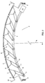
- the ventilating hatch shown in top plan view in Fig. 1 which may for instance be mounted on the roof of a building, comprises a framework 1 consisting of two opposite longitudinal sides 2 following an arcuate curve in the same direction relative to their axes, as can be clearly seen in Fig. 2, and two opposite transverse sides 3.
- the hatch opening 4 so formed by the framework 1 is divided into a plurality of hatch compartments 6 by a plurality of profiled members 5, U-shaped with the legs directed outwardly and arranged substantially parallel to the transverse sides 3.
- Each of these hatch compartments 6 can be closed off by a separate closing member 7 fitted in a frame section (not shown), each closing member 7 being adapted for hinge movement relative to a longitudinal end thereof about a corresponding hinge pin 8.
- These hinge pins extend parallel to a transverse side 3 of the framework 1 and have their ends hinged to the longitudinal sides 2 of the framework 1.
- the closing members 7 can be flat members or have a curved configuration following the arcuate curve of longitudinal sides 2.
- each of the closing members 7 With downwardly directed rims (not shown) and a resilient sealing construction arranged around the frame section, a draught, water and snow tight seal can be obtained.
- any water disposed on the closing members 7 can be drained laterally of the ventilating hatch via the profiled members, and thus water is prevented from entering the space below.
- a common pull rod 9 for opening and closing the closing members, there is provided a common pull rod 9, whose axis follows a substantially arcuate curve and is substantially equal to the curve of the longitudinal sides 2 of the framework 1.
- the pull rod 9 is arranged such that it extends coaxially with the longitudinal sides 2, and hence with the series of closing members 7, and substantially perpendicularly to the hinge pins 8 of the closing members 7.
- Via a plurality of substantially identical connecting arms 10 the pull rod 9 is coupled to the corresponding closing members 7.
- the connecting arms are, at one end, rigidly coupled to the closing members, and, at the other, hinged to the pull rod 9 at hinge joints 11.
- the connecting arms 10 are so constructed that, in the closed position of the closing members, the hinge joints 11 of the arms 10 on the pull rod 9 are disposed at the same predetermined distance before the hinge pins 8 of the corresponding closing members 7, as viewed in the opening direction of the pull rod (direction of arrow P).
- Fig. 3 shows that the predetermined distance equals the distance 'a' from the hinge joints 11 to the plane 12 which is perpendicular to the pull rod 9 and includes the hinge pin of the associated hinge joint, and that, in the opened position of the closing members, the hinge joints are disposed at the same predetermined distance 'a' on the other side of these perpendicular planes 12.
- the hinge joints are at a distance 'a' such that the angle ⁇ between the perpendicular plane and the line going through the hinge joints 11 and the associated hinge pins 8 of the closing members 7 is approximately 40°, which means that the closing members 7 can be opened through an angle of approximately 80°. It will be clear that the angle ⁇ can have other desired values.
- the pull rod 9 although it will first come down slightly since the hinge joints 11 traverse circular paths b during their displacement- after completion of an opening or closing movement, will invariably end up at the same radial distance R from its fixed centre, i.e. that the centre of the arc of the pull rod is in the same point before and after the opening and closing movement.
- the pull rod 9 can be simply driven by for instance a hydraulic drive 13 which can be arranged adjacent the ventilating hatch and which can be remote-controlled.
- the drive 13 can be effected electrically, pneumatically or by hand.
- the pull rod 9 can be arranged in the middle of the ventilating hatch or on one side or on both sides, for instance when the ventilating hatch has very large dimensions.
- the closing members 7 can be so arranged that they overlap. In that case, the provision of profiled members 5 can be omitted.
- end partitions 14 which are arranged at the two transverse sides 3 of the framework 1. These end partitions need only be of limited height to enable sufficient deflection of the wind and certainly need not project above the highest closing members 7. If necessary, also longitudinal partitions (not shown) can be arranged at the two longitudinal sides 2 of the framework 1, for instance to meet local fire security regulations.
Landscapes
- Engineering & Computer Science (AREA)
- Chemical & Material Sciences (AREA)
- Combustion & Propulsion (AREA)
- Mechanical Engineering (AREA)
- General Engineering & Computer Science (AREA)
- Architecture (AREA)
- Physics & Mathematics (AREA)
- Electromagnetism (AREA)
- Civil Engineering (AREA)
- Structural Engineering (AREA)
- Specific Sealing Or Ventilating Devices For Doors And Windows (AREA)
- Catching Or Destruction (AREA)
Claims (3)
- Lüftungsluke mit einem die Lukenöffnung umgebenden Rahmen, dessen Längsseiten in bezug auf ihre Achsen in derselben Richtung einer im allgemeinen bogenförmigen Kurve folgen, welche entsprechend gebogene Lukenöffnung mit einem mit dieser zusammenwirkenden scharnierbaren Abschlußdeckel abschließbar ist, dadurch gekennzeichnet, daß der Abschlußdeckel eine Anzahl einzelner Abschlußelemente (7) enthält, die je in bezug auf eines ihrer Längsenden um einen zugeordneten mit den Längsseiten (2) des Rahmens (1) gekuppelten Scharnierstift (8) scharnierbar sind, welche Scharnierstifte (8) parallel zur Querseite (3) des Rahmens (1) verlaufen, und daß zum Öffnen und Schließen jedes der Abschlußelemente (7) eine gemeinsame Zugstange (9) vorgesehen ist, deren Achse einer im wesentlichen bogenförmigen Kurve folgt, und welche Kurve im wesentlichen gleich der bogenförmigen Kurve der Längsseiten (2) des Rahmens (1) ist, wobei die Zugstange (9) so angeordnet ist, daß diese im wesentlichen senkrecht auf den Scharnierstiften (8) steht; und eine der Anzahl Abschlußelemente (7) entsprechende Anzahl Verbindungsarme (10), die je einerseits an die zugeordneten Abschlußelemente (7) gekuppelt und andererseits gelenkig mit der Zugstange (9) verbunden sind, wobei die Gelenkpunkte (11) der Verbindungsarme (10) an einer solchen Stelle an der Zugstange (9) angeordnet sind, daß beim Ziehen oder Schieben der Zugstange (9) in Richtung ihrer Achse zum Öffnen bzw. Schließen der Abschlußelemente (7) der Mittelpunkt (M) des Bogens der Zugstange sowohl in Schließlage als auch in Offenlage der Abschlußelemente (7) im wesentlichen an derselben Stelle fixiert ist.
- Lüftungsluke nach Anspruch 1, dadurch gekennzeichnet, daß jeder der Verbindungsarme (10) so ausgebildet ist, daß ihre Gelenkpunkte (11) in Schließlage der Abschlußelemente (7) an die Zugstange (9) im gleichen vorbestimmten Abstand (a) vor den Scharnierstiften (8) der zugeordneten Abschlußelemente (7) gekuppelt sind, gesehen in der Öffnungsrichtung der Zugstange (9), wobei diese vorbestimmten Abstände (a) gleich dem Abstand von den Gelenkpunkten (11) zu der senkrecht auf der Zugstange (9) stehenden und die Scharnierstifte (8) enthaltenden Ebene (12) sind, und daß in Offenlage der Abschlußelemente (7) die Gelenkpunkte (11) im gleichen vorbestimmten Abstand an der anderen Seite der senkrechten Ebenen (12) angeordnet sind.
- Lüftungsluke nach Anspruch 2, dadurch gekennzeichnet, daß der Winkel (α) zwischen der senkrechten Ebene (12) und der durch den Gelenkpunkt (11) und den zugeordneten Scharnierstift (8) verlaufenden Linie vorzugsweise etwa gleich 40° ist.
Priority Applications (1)
| Application Number | Priority Date | Filing Date | Title |
|---|---|---|---|
| AT91201574T ATE103059T1 (de) | 1990-06-22 | 1991-06-19 | Lueftungsluke. |
Applications Claiming Priority (2)
| Application Number | Priority Date | Filing Date | Title |
|---|---|---|---|
| NL9001436 | 1990-06-22 | ||
| NL9001436A NL9001436A (nl) | 1990-06-22 | 1990-06-22 | Ventilatieluik. |
Publications (2)
| Publication Number | Publication Date |
|---|---|
| EP0463697A1 EP0463697A1 (de) | 1992-01-02 |
| EP0463697B1 true EP0463697B1 (de) | 1994-03-16 |
Family
ID=19857301
Family Applications (1)
| Application Number | Title | Priority Date | Filing Date |
|---|---|---|---|
| EP91201574A Expired - Lifetime EP0463697B1 (de) | 1990-06-22 | 1991-06-19 | Lüftungsluke |
Country Status (4)
| Country | Link |
|---|---|
| EP (1) | EP0463697B1 (de) |
| AT (1) | ATE103059T1 (de) |
| DE (1) | DE69101402T2 (de) |
| NL (1) | NL9001436A (de) |
Families Citing this family (8)
| Publication number | Priority date | Publication date | Assignee | Title |
|---|---|---|---|---|
| FR2701977B1 (fr) * | 1993-02-26 | 1995-04-14 | Christian Manenc | Système de toiture ouvrante, notamment pour véranda. |
| WO1996006258A1 (de) * | 1994-08-19 | 1996-02-29 | Paul Schlossbauer | Aus platten gebildete wand- oder dachfläche |
| DE19528302C2 (de) * | 1995-08-02 | 2000-08-24 | Maico Elektroapparate | Verschlußvorrichtung für eine lufttechnische Einrichtung |
| DE19600205C2 (de) * | 1996-01-04 | 2003-06-26 | Schultz Gmbh Aurora | Luftdüse |
| WO2004013544A1 (en) * | 2002-08-01 | 2004-02-12 | Solutions Jupiter Inc. | Louvers slats with flexible gutters |
| CN103004619A (zh) * | 2012-11-28 | 2013-04-03 | 巫溪县银龙畜禽养殖有限公司 | 分块组合式猪圈屋顶 |
| CN106482310B (zh) * | 2016-11-02 | 2019-04-26 | 山西尚风抑风墙科技有限公司 | 一种控制若干通风口大小的控制结构 |
| CN110915658A (zh) * | 2019-12-25 | 2020-03-27 | 四川金仕达自动化设备有限公司 | 一种新型保温板联动开关装置 |
Family Cites Families (3)
| Publication number | Priority date | Publication date | Assignee | Title |
|---|---|---|---|---|
| GB1374739A (en) * | 1973-05-16 | 1974-11-20 | Voest Ag | Actuator for roof venting flaps |
| FR2382554A1 (fr) * | 1977-03-02 | 1978-09-29 | Souchier Georges | Dispositif d'evacuation des fumees, notamment pour locaux industriels |
| FR2405638A1 (fr) * | 1977-10-14 | 1979-05-11 | Richel Pierre | Dispositif fonctionnel de serres chapelles |
-
1990
- 1990-06-22 NL NL9001436A patent/NL9001436A/nl not_active Application Discontinuation
-
1991
- 1991-06-19 EP EP91201574A patent/EP0463697B1/de not_active Expired - Lifetime
- 1991-06-19 AT AT91201574T patent/ATE103059T1/de not_active IP Right Cessation
- 1991-06-19 DE DE69101402T patent/DE69101402T2/de not_active Expired - Fee Related
Also Published As
| Publication number | Publication date |
|---|---|
| DE69101402D1 (de) | 1994-04-21 |
| EP0463697A1 (de) | 1992-01-02 |
| ATE103059T1 (de) | 1994-04-15 |
| NL9001436A (nl) | 1992-01-16 |
| DE69101402T2 (de) | 1994-07-07 |
Similar Documents
| Publication | Publication Date | Title |
|---|---|---|
| EP0463697B1 (de) | Lüftungsluke | |
| US5655559A (en) | Shelter | |
| US5149301A (en) | Baffle means for roof ridge ventilator | |
| US4315345A (en) | Profiled hinge joint | |
| US10988936B2 (en) | Pergola louver tilt system | |
| EP0951609B1 (de) | Fenster, insbesondere für den einbau in eine geneigte dachfläche | |
| AU637222B2 (en) | A hinge suitable for use in a roof window assembly | |
| JP4916348B2 (ja) | 排気用ルーフファン用シャッター装置 | |
| US6105529A (en) | Hatch adjuster | |
| US1283338A (en) | Roof structure. | |
| US758510A (en) | Chimney. | |
| WO1991011586A1 (en) | Window operator for use with awning window assembly | |
| ES2929314T3 (es) | Cerradura de varilla | |
| US1898813A (en) | Skylight | |
| US5217407A (en) | Fire damper with auxiliary springs | |
| EP3564461B1 (de) | Dachfenster mit verbesserter abdeckungsanordnung | |
| EP0607791B1 (de) | Dachflächenentlüfter | |
| CN223497449U (zh) | 一种新型圆拱形天窗 | |
| SE507005C2 (sv) | Ledarmsbeslag med barnsäkring | |
| EP0434716B1 (de) | Fenster mit oben angelenktem rahmen für den einbau in schrägdächern | |
| US1103461A (en) | Dormer. | |
| GB1595027A (en) | Device for ventilating a greenhouse | |
| AU759787B2 (en) | Roof ventilator | |
| SU1342517A1 (ru) | Устройство противопожарной системы театральной сцены | |
| KR101569092B1 (ko) | 내부에서 보수 가능한 환기창 |
Legal Events
| Date | Code | Title | Description |
|---|---|---|---|
| PUAI | Public reference made under article 153(3) epc to a published international application that has entered the european phase |
Free format text: ORIGINAL CODE: 0009012 |
|
| AK | Designated contracting states |
Kind code of ref document: A1 Designated state(s): AT BE CH DE DK ES FR GB GR IT LI LU NL SE |
|
| 17P | Request for examination filed |
Effective date: 19911204 |
|
| 17Q | First examination report despatched |
Effective date: 19930625 |
|
| GRAA | (expected) grant |
Free format text: ORIGINAL CODE: 0009210 |
|
| AK | Designated contracting states |
Kind code of ref document: B1 Designated state(s): AT BE CH DE DK ES FR GB GR IT LI LU NL SE |
|
| PG25 | Lapsed in a contracting state [announced via postgrant information from national office to epo] |
Ref country code: IT Free format text: LAPSE BECAUSE OF FAILURE TO SUBMIT A TRANSLATION OF THE DESCRIPTION OR TO PAY THE FEE WITHIN THE PRE;WARNING: LAPSES OF ITALIAN PATENTS WITH EFFECTIVE DATE BEFORE 2007 MAY HAVE OCCURRED AT ANY TIME BEFORE 2007. THE CORRECT EFFECTIVE DATE MAY BE DIFFERENT FROM THE ONE RECORDED.SCRIBED TIME-LIMIT Effective date: 19940316 Ref country code: DK Effective date: 19940316 Ref country code: GR Free format text: LAPSE BECAUSE OF FAILURE TO SUBMIT A TRANSLATION OF THE DESCRIPTION OR TO PAY THE FEE WITHIN THE PRESCRIBED TIME-LIMIT Effective date: 19940316 Ref country code: ES Free format text: THE PATENT HAS BEEN ANNULLED BY A DECISION OF A NATIONAL AUTHORITY Effective date: 19940316 Ref country code: SE Free format text: THE PATENT HAS BEEN ANNULLED BY A DECISION OF A NATIONAL AUTHORITY Effective date: 19940316 |
|
| REF | Corresponds to: |
Ref document number: 103059 Country of ref document: AT Date of ref document: 19940415 Kind code of ref document: T |
|
| REF | Corresponds to: |
Ref document number: 69101402 Country of ref document: DE Date of ref document: 19940421 |
|
| PG25 | Lapsed in a contracting state [announced via postgrant information from national office to epo] |
Ref country code: LU Free format text: LAPSE BECAUSE OF NON-PAYMENT OF DUE FEES Effective date: 19940630 |
|
| ET | Fr: translation filed | ||
| PLBE | No opposition filed within time limit |
Free format text: ORIGINAL CODE: 0009261 |
|
| STAA | Information on the status of an ep patent application or granted ep patent |
Free format text: STATUS: NO OPPOSITION FILED WITHIN TIME LIMIT |
|
| 26N | No opposition filed | ||
| PGFP | Annual fee paid to national office [announced via postgrant information from national office to epo] |
Ref country code: CH Payment date: 19951228 Year of fee payment: 5 |
|
| PG25 | Lapsed in a contracting state [announced via postgrant information from national office to epo] |
Ref country code: LI Effective date: 19960630 Ref country code: CH Effective date: 19960630 |
|
| REG | Reference to a national code |
Ref country code: CH Ref legal event code: PL |
|
| REG | Reference to a national code |
Ref country code: GB Ref legal event code: IF02 |
|
| PGFP | Annual fee paid to national office [announced via postgrant information from national office to epo] |
Ref country code: NL Payment date: 20090616 Year of fee payment: 19 |
|
| PGFP | Annual fee paid to national office [announced via postgrant information from national office to epo] |
Ref country code: AT Payment date: 20090625 Year of fee payment: 19 |
|
| PGFP | Annual fee paid to national office [announced via postgrant information from national office to epo] |
Ref country code: FR Payment date: 20090626 Year of fee payment: 19 |
|
| PGFP | Annual fee paid to national office [announced via postgrant information from national office to epo] |
Ref country code: GB Payment date: 20090616 Year of fee payment: 19 Ref country code: DE Payment date: 20090624 Year of fee payment: 19 |
|
| PGFP | Annual fee paid to national office [announced via postgrant information from national office to epo] |
Ref country code: BE Payment date: 20090710 Year of fee payment: 19 |
|
| BERE | Be: lapsed |
Owner name: *PEETERS HUBERTUS GERARDUS JACOBUS Effective date: 20100630 |
|
| REG | Reference to a national code |
Ref country code: NL Ref legal event code: V1 Effective date: 20110101 |
|
| GBPC | Gb: european patent ceased through non-payment of renewal fee |
Effective date: 20100619 |
|
| REG | Reference to a national code |
Ref country code: FR Ref legal event code: ST Effective date: 20110228 |
|
| PG25 | Lapsed in a contracting state [announced via postgrant information from national office to epo] |
Ref country code: DE Free format text: LAPSE BECAUSE OF NON-PAYMENT OF DUE FEES Effective date: 20110101 |
|
| PG25 | Lapsed in a contracting state [announced via postgrant information from national office to epo] |
Ref country code: FR Free format text: LAPSE BECAUSE OF NON-PAYMENT OF DUE FEES Effective date: 20100630 Ref country code: AT Free format text: LAPSE BECAUSE OF NON-PAYMENT OF DUE FEES Effective date: 20100619 Ref country code: NL Free format text: LAPSE BECAUSE OF NON-PAYMENT OF DUE FEES Effective date: 20110101 |
|
| PG25 | Lapsed in a contracting state [announced via postgrant information from national office to epo] |
Ref country code: BE Free format text: LAPSE BECAUSE OF NON-PAYMENT OF DUE FEES Effective date: 20100630 |
|
| PG25 | Lapsed in a contracting state [announced via postgrant information from national office to epo] |
Ref country code: GB Free format text: LAPSE BECAUSE OF NON-PAYMENT OF DUE FEES Effective date: 20100619 |