EP0463785A1 - Toilette pour véhicule de loisir avec pédale de chasse d'eau - Google Patents
Toilette pour véhicule de loisir avec pédale de chasse d'eau Download PDFInfo
- Publication number
- EP0463785A1 EP0463785A1 EP91305489A EP91305489A EP0463785A1 EP 0463785 A1 EP0463785 A1 EP 0463785A1 EP 91305489 A EP91305489 A EP 91305489A EP 91305489 A EP91305489 A EP 91305489A EP 0463785 A1 EP0463785 A1 EP 0463785A1
- Authority
- EP
- European Patent Office
- Prior art keywords
- pedal
- bowl
- flush water
- closure member
- housing
- Prior art date
- Legal status (The legal status is an assumption and is not a legal conclusion. Google has not performed a legal analysis and makes no representation as to the accuracy of the status listed.)
- Ceased
Links
Images

Classifications
-
- E—FIXED CONSTRUCTIONS
- E03—WATER SUPPLY; SEWERAGE
- E03D—WATER-CLOSETS OR URINALS WITH FLUSHING DEVICES; FLUSHING VALVES THEREFOR
- E03D5/00—Special constructions of flushing devices, e.g. closed flushing system
- E03D5/02—Special constructions of flushing devices, e.g. closed flushing system operated mechanically or hydraulically (or pneumatically) also details such as push buttons, levers and pull-card therefor
- E03D5/08—Special constructions of flushing devices, e.g. closed flushing system operated mechanically or hydraulically (or pneumatically) also details such as push buttons, levers and pull-card therefor directly by the foot combined with devices for opening or closing shutters in the bowl outlet and/or with devices for raising or lowering seat and cover and/or for swiveling the bowl
-
- E—FIXED CONSTRUCTIONS
- E03—WATER SUPPLY; SEWERAGE
- E03D—WATER-CLOSETS OR URINALS WITH FLUSHING DEVICES; FLUSHING VALVES THEREFOR
- E03D5/00—Special constructions of flushing devices, e.g. closed flushing system
- E03D5/012—Special constructions of flushing devices, e.g. closed flushing system combined with movable closure elements in the bowl outlet
Definitions
- the present invention relates to improvements in the flush mechanism for toilets and in particular to toilets of the type where in the toilet bowl discharges to a holding tank and a closure member is provided for opening and closing the discharge outlet from the bowl to the holding tank.
- Toilets of this character are commonly used in mobile homes, recreational vehicles, marine vessels and the like.
- U.S. Patent No. 4,185,340 commonly assigned, the specification of which is hereby incorporated by reference.
- This patent discloses a toilet apparatus having a hand operated flush mechanism.
- the toilet disclosed in the referenced patent does not include a flush water storage tank located above the bowl with a flush actuator as in a typical residential toilet.
- the hand operated flush controls are located at the top of the bowl. This location requires the toilet user to stoop over the bowl to reach the controls. This may be difficult for elderly or handicapped persons and may also be an unpleasant task.
- the present invention provides a foot controlled flush mechanism for improving the ease by which the toilet is flushed.
- the hand operated flush control levers of the toilet disclosed in the referenced patent are replaced by wire actuated control levers that are operated by foot pedals.
- the pedals are pivotally mounted to the toilet housing at a position near the base of the toilet for easy operation by a toilet user without requiring stooping over the bowl.
- Two pedals are provided, one for operating the flush water supply to the bowl and the other for operating the closure member at the bowl discharge outlet.
- the flush water pedal can be operated independently of the closure member pedal for use in partially filling the bowl with water before use of the toilet. After toilet use, the closure member pedal is actuated to open the bowl discharge outlet.
- the closure member pedal coacts with the water pedal to simultaneously actuate the water pedal to provide water for flushing.
- the flush mechanism includes a return spring to automatically return the control levers to their normal positions when the foot pedals are released. It is a further object of the invention to provide a flush mechanism which, in the event of a failure of the return spring, enables the pedals to be manually raised to return the control levers to their normal positions.
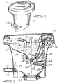
- Figure 1 is a perspective view of a toilet apparatus having foot pedal flush controls of the present invention.
- Figure 2 is a vertical sectional view, with portions broken away for illustration, of the toilet apparatus shown in Figure 1.
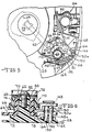
- Figure 3 is a bottom view of the toilet apparatus of Figure 1.
- Figure 4 is a sectional view as seen from substantially the line 4-4 of Figure 3 with the water pedal depressed.
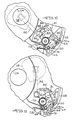
- Figure 5 is an enlarged fragmentary plan view of the flush control mechanism with the water control levers in closed positions.
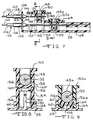
- Figure 6 is a sectional view of the control mechanism as seen from substantially the line 6-6 of Figure 5.
- Figure 7 is a sectional view of the control mechanism as seen from substantially the line 7-7 of Figure 5.
- Figure 8 is a sectional view of the control mechanism as seen from substantially the line 8-8 of Figure 7.
- Figure 9 is a sectional view of the control mechanism as seen from substantially the line 9-9 of Figure 7.
- Figure 10 is an enlarged fragmentary plan view of the control mechanism with the water lever rotated to an open position.
- Figure 11 is a view similar to Figure 10 with both the levers in open positions.
- the toilet 20 comprises a bowl 22 having at its lower end a discharge outlet 24 defined by the downwardly projecting flange 26.
- the upper end of the bowl 22 is open and has an outwardly directed peripheral flange 28 that is supported on and is secured to a housing 30.
- the housing 30 defines an outlet 32 leading to a holding tank (not shown) via the conduit 34. Waste material from the bowl 22 can be discharged through the outlets 24 and 32 when the sealing mechanism 36 is in an open position.
- Sealing mechanism 36 can be moved between open and closed positions for opening and closing the bowl outlet 26.
- Sealing mechanism 36 includes as a closure member the blade 38 having a downwardly opening socket 40 located centrally of the blade.
- the sealing mechanism also includes a crank arm 42 that has a shaft portion 44 providing an essentially vertical axis about which the crank arm 42 can pivot.
- the crank arm 42 has a finger 46 at its radially outer end for supporting the blade 38 surrounded by a collar 48 extending into the socket 40.
- the shaft portion 44 is supported on the post 50 of the housing 30 and is guided for pivotal movement in the cylindrical bearing surface 52 of flange 28 which is integrally joined to housing 30.
- a coil spring 54 is positioned between the post 50 and the shaft portion 44 to urge crank arm 42 in an upward direction. Additional details of the blade 38 are provided in the referenced patent.
- a seal member 56 is mounted in a sealing relationship to the bottom of the bowl 22 around outlet 24.
- the seal member 56 is an elastomeric sleeve which projects below the lower edge of the outlet 24 so as to provide an elastic curtain or a projecting portion below the lower edge of the flange.
- the seal member 56 is enclosed around its outer periphery by a collar 58 that is snap fit onto the bowl 22 around the outlet 24.
- a control mechanism 60 is used for moving the sealing mechanism 36 to its open and closed positions and for supplying flush water to the bowl.
- a pivot member or post 62 is integrally formed with flange 28.
- Mounted on the post 62 for pivotal movement with respect thereto are the closure member control lever 64 and the flush water control lever 66.
- Closure member lever 64 includes a sleeve portion 68 telescoped over the pivot post 62 and has a radial bearing portion 70 at its upper end engaging the pivot post. The lower portion of the lever 64 engages a lower radial shoulder 72 of the pivot post to retain sleeve portion 68 concentric about the pivot post.
- the water lever 66 includes a sleeve portion 74 telescoped over the sleeve portion 68 of the lever 64 and also includes a bearing portion 76 engaging the sleeve portion 68 of the lever 64.
- a cylindrical bushing 78 is placed between the sleeve portions of the two levers to maintain the alignment of the two levers. The levers are held in place on the pivot post 62 by a washer 80 and screw 82.
- the closure member lever 64 is operatively associated with the crank arm 42 to impart the movement required to move the blade 38 between the closed and open positions.
- the upper end of shaft portion 44 of crank arm 42 has a small crank arm 84.
- the small crank arm 84 has a raised cam follower 86 at its end for traveling in slot 88 in the lever 64.
- Slot 88 is generally dog legged in shape having a first primarily circumferentially directed portion 89 and a second portion 90 having a substantial radially directed component.
- the slot 88 is shaped so that when the lever 64 is moved clockwise from a position shown in Figure 5, the small crank arm 84 will not change its radial position while the cam follower travels through the first portion 89 of the slot.
- Water is provided to the bowl for flushing upon actuation of the water lever 66.
- water lever 66 can be independently actuated to provide water for partially filling the bowl 22.
- Water lever 66 is automatically actuated upon actuation of the closure member lever 64 so as to provide water to the bowl for flushing when the blade 38 is moved to the open position.
- Water lever 66 has one end of a linkage 91 connected thereto as shown in Figure 5. The other end of the linkage 91 is connected to a crank 92 of a water flow control valve assembly 94.
- Control valve assembly 94 includes a inlet fitting (not shown) for connection to an external source of water through hose 96.
- the control valve assembly 94 includes an outlet and flush tube 98 for directing water to the nozzle 100.
- the crank 92 will also pivot, opening the control valve assembly allowing water to flow from the source of supply into the flush tube 98 and from there to nozzle 100.
- the nozzle 100 is mounted in the bowl 22 to direct a jet of water into the bowl for flow in a vortex pattern.
- the nozzle has a small aperture 102 therein to allow small quantities of water to descend during flushing into the overflow drain outlet 104 so as to maintain water in the overflow tube 106.
- the tube 106 is supported adjacent to its mid-portion by a hook 108 which is mounted in the bowl 22 so as to provide a water trap to prevent odors, gases and the like escaping from the regions below the bowl 22 through the overflow tube 106.
- the latter has its lower end terminating in the enclosure 109 so that limited quantities of water that flow from the overflow tube can drop onto the top of blade 38 while it is in its open position as described in greater detail in the referenced patent.
- the closure member lever 64 and water lever 66 are actuated by two pedals, a closure member pedal 110 and a flush pedal 112.
- Pedals 110 and 112 are pivotally mounted to the housing 30 adjacent the lower end of the housing as shown in Figures 1-4.
- the pedals 110 and 112 are integrally formed with U-shaped mounting arms 114 and 116 respectively.
- the terminal ends of the mounting arms are pivotally connected to the housing 30 through mounting brackets 118 fastened to the housing 30 on opposite sides.
- the two mounting brackets define an axis 120 about which both pedals pivot.
- a portion 122 of pedal 110 overlies a portion 123 of the pedal 112.
- the mounting arm 114 of pedal 110 overlies the mounting arm 116 of pedal 112.
- the closure member pedal 110 and the flush water pedal 112 are connected to the levers 64 and 66 respectively through actuating wire assemblies 122 and 124 respectively.
- Actuating wire assemblies 122 and 124 include conduits 126 and 128 respectively and solid wires 130 and 132 respectively which are longitudinally slidable within the conduits.
- the ends of the wire assemblies include fittings 134 for attaching the conduits to the housing 30.
- a flange 136 extends inwardly from the housing and includes a slotted opening 138 into which an end fitting 134 is snap-fit to secure the wire assembly 122 thereto.
- a downturned portion 140 of the flange 136 serves as a stop to limit the upward rotation of pedals 110 and 112.
- the end of the closure member wire 130 is shown attached to closure member pedal 110 by retainer clip 142 sandwiching the pedal therebetween.
- the clip 142 is used to enable both pushing and pulling of the wire 130 through conduit 126 as will be described below.
- the opposite ends of the wire assemblies 122 and 124 are snap-fit into slotted openings 142 and 144 in the upturned flange 146 extending from the bowl periphery flange 28. Connection of the wire assemblies to the control levers is described below with reference to connection of the water wire 132 to the water control lever 66.
- a small diameter ball 148 is pressed onto the wire 132.
- a hollow guide pin 150 is inserted through slot 151 in the water lever 66 and over the wire 132 and ball 148.
- the guide pin 150 includes two longitudinal slots 152 which enable the guide pin to be fitted over the ball and wire.
- the slots 152 form two fingers 154 in the guide pin 150 which can be resiliently deflected. Each of the fingers 154 includes a window 156.
- Retainer 158 includes two projecting tabs 160 on opposite sides. As the retainer is inserted into the guide pin, the tabs 160 deflect the fingers 154 outwardly until the retainer has been inserted far enough into the guide pin to align the tabs with the windows 156. The fingers 154 are then allowed to return to their normal state, seating tabs 160 in the windows to lock retainer 158 in place. The ball 148 is thus captured in the guide pin 150 causing the guide pin to be moved with movement of the wire 132 and ball 148.
- the flange 28 includes two raised parallel arcuate track members 162 and 164.
- the guide pin 150 is positioned between the two track members 162 and 164 so that as the guide pin is moved, it follows the arcuate path defined by the two track members.
- Slot 151 is provided in the water lever 66 for the guide pin 150 to travel in because the arcuate path defined by the track members 162 and 164 is not concentric about the pivot post 62.
- the arcuate path is not concentric with post 62 to avoid bending wire 132 on a smaller radius than which it can be easily bent.
- the wire 130 in closure member wire assembly 122 is connected to the closure member lever 64 by a similar guide pin 150a which is identical to guide pin 150 except for a shorter vertical height. Portions of guide pin 150a and the wire connection that are similar to portions of guide pin 150 and its wire connection are designated by the same reference numeral followed by the suffix "a". Guide pin 150a also follows the arcuate path of track members 162 and 164. Accordingly, the closure member lever 64 includes a slot 166 similar to slot 151 in control lever 66. During clockwise rotation of the lever 64, the guide pin 150a travels through slot 166 from the position shown in Figure 5 to that of Figure 11. Wire 130 extends beyond the guide pin 150a into a wire guide 168 to help ensure the proper radius bend in the portion of wire 130 extending from conduit 126.
- a torsion spring 170 is placed over the sleeve portion 74 of the water lever 66 for use in biasing the water lever to the closed position of the control valve assembly 94.
- Spring end 172 engages the flange 146 while the other spring end 174 engages the water lever 66.
- Clockwise rotation of the water lever 66 increases the torsional stress in spring 170 such that when the water pedal is released, the spring will return water lever 66 to the position shown in Figure 5 in which the control valve assembly 94 is closed. The return of water lever 66 will pull on wire 132 raising the water pedal 112.
- Wires 130 and 132 are solid wires to provide sufficient strength to accommodate compression loads necessary to push on the wires to return levers 64 and 66.
- the toilet is thus provided with foot pedal flush controls for easier operation not requiring the user to stoop over the bowl.
- the connection of the pedals to the flush and water levers enables the pedals to be used to close the bowl outlet and water valve assembly in the event the return spring fails.
Landscapes
- Engineering & Computer Science (AREA)
- Aviation & Aerospace Engineering (AREA)
- Health & Medical Sciences (AREA)
- Life Sciences & Earth Sciences (AREA)
- Hydrology & Water Resources (AREA)
- Public Health (AREA)
- Water Supply & Treatment (AREA)
- Mechanical Engineering (AREA)
- Sanitary Device For Flush Toilet (AREA)
- Toilet Supplies (AREA)
Applications Claiming Priority (2)
| Application Number | Priority Date | Filing Date | Title |
|---|---|---|---|
| US07/542,528 US5060320A (en) | 1990-06-25 | 1990-06-25 | Recreational vehicle toilet with foot pedal flush |
| US542528 | 1990-06-25 |
Publications (1)
| Publication Number | Publication Date |
|---|---|
| EP0463785A1 true EP0463785A1 (fr) | 1992-01-02 |
Family
ID=24164214
Family Applications (1)
| Application Number | Title | Priority Date | Filing Date |
|---|---|---|---|
| EP91305489A Ceased EP0463785A1 (fr) | 1990-06-25 | 1991-06-18 | Toilette pour véhicule de loisir avec pédale de chasse d'eau |
Country Status (3)
| Country | Link |
|---|---|
| US (1) | US5060320A (fr) |
| EP (1) | EP0463785A1 (fr) |
| CA (1) | CA2045017C (fr) |
Cited By (3)
| Publication number | Priority date | Publication date | Assignee | Title |
|---|---|---|---|---|
| EP1348060A4 (fr) * | 2000-11-28 | 2006-01-25 | Sealand Technology Inc | Toilettes et leur proc d de fonctionnement |
| CN103206006A (zh) * | 2012-01-16 | 2013-07-17 | 李殿治 | 脚踏式翻斗座便器 |
| CN103437409A (zh) * | 2012-11-16 | 2013-12-11 | 陈林长 | 速排止逆环保便器 |
Families Citing this family (26)
| Publication number | Priority date | Publication date | Assignee | Title |
|---|---|---|---|---|
| DE4024646C1 (fr) * | 1990-08-03 | 1992-02-27 | Rolf 3320 Salzgitter De Wesemann | |
| USD387139S (en) * | 1996-05-15 | 1997-12-02 | Sim Jae K | Toilet for a recreational vehicle |
| US5875499A (en) * | 1998-01-23 | 1999-03-02 | Thetford Corporation | Recreational vehicle toilet with flush nozzle deflector shield |
| US5933882A (en) * | 1998-06-05 | 1999-08-10 | Sanitation Equipment Limited | Lever-actuated flush toilet |
| USD484957S1 (en) | 2002-11-30 | 2004-01-06 | Thetford Corporation | Flush toilet |
| USD485604S1 (en) | 2002-11-30 | 2004-01-20 | Thetford Corporation | Flush toilet |
| USD485334S1 (en) | 2002-11-30 | 2004-01-13 | Thetford Corporation | Flush toilet shroud |
| AU2003295995A1 (en) * | 2002-11-30 | 2004-06-23 | Thetford Corporation | Reduced water consumption flush toilet |
| USD484580S1 (en) | 2002-11-30 | 2003-12-30 | Thetford Corporation | Flush toilet |
| EP1536073A3 (fr) | 2003-11-26 | 2007-05-16 | Thetford Corporation | WC à consommation d'eau réduite ayant un mécanisme d'actuation commun qui contrôle une valve d'eau par un premier câble flexible et une valve d'eaux usées par un deuxième câble flexible |
| US20050283893A1 (en) * | 2004-06-23 | 2005-12-29 | Dan Delaney | Bench-type waste transfer arrangement |
| USD536076S1 (en) | 2005-06-22 | 2007-01-30 | Thetford Corporation | Self-contained, bench-type sanitary system |
| US20070011801A1 (en) * | 2005-07-18 | 2007-01-18 | Dubois R C | Toilet with spinning bowl and water jet |
| USD537151S1 (en) * | 2005-11-09 | 2007-02-20 | Thetford Corporation | Toilet |
| USD531711S1 (en) * | 2006-01-31 | 2006-11-07 | Dometic Sanitation Corporation | Toilet |
| US7765625B2 (en) | 2006-02-17 | 2010-08-03 | Thetford Corporation | Flush toilet assembly |
| US8225819B2 (en) * | 2006-08-11 | 2012-07-24 | Thetford Corporation | Portable waste transfer tank |
| US20080040846A1 (en) * | 2006-08-18 | 2008-02-21 | Bernard Cheng | No-flush direct urine disposal system |
| USD603028S1 (en) * | 2008-02-29 | 2009-10-27 | Kohler France Sas | Plumbing fixture |
| US20090255477A1 (en) * | 2008-03-31 | 2009-10-15 | Fournier Curt R | Animal waste management device |
| US9879437B2 (en) * | 2013-02-05 | 2018-01-30 | Bertram Y. ITO | Transportable restroom |
| US9957701B2 (en) | 2013-02-05 | 2018-05-01 | Bertram Y. ITO | Roof assembly for a transportable restroom |
| US9340963B2 (en) | 2013-02-05 | 2016-05-17 | Bertram Y. ITO | Transportable restroom |
| JP6305247B2 (ja) * | 2014-06-13 | 2018-04-04 | 株式会社日立ハイテクサイエンス | 蛍光x線分析装置 |
| US10501923B2 (en) * | 2017-04-10 | 2019-12-10 | B/E Aerospace, Inc. | Method and apparatus for controlling a waste outlet of a toilet |
| USD1052057S1 (en) * | 2023-01-04 | 2024-11-19 | Fujian Aidi Electric Co., Ltd. | Toilet |
Citations (3)
| Publication number | Priority date | Publication date | Assignee | Title |
|---|---|---|---|---|
| US3835479A (en) * | 1973-04-04 | 1974-09-17 | Itt | Toilet valve assembly |
| DE2440853A1 (de) * | 1973-08-28 | 1975-04-03 | Matsushita Electric Works Ltd | Spuelklosett |
| US4710988A (en) * | 1986-02-19 | 1987-12-08 | Sanitation Equipment Limited | Flush toilet |
Family Cites Families (6)
| Publication number | Priority date | Publication date | Assignee | Title |
|---|---|---|---|---|
| US3340545A (en) * | 1965-04-02 | 1967-09-12 | Thetford Engineering Corp | Water closet |
| US3369260A (en) * | 1965-10-22 | 1968-02-20 | Thetford Engineering Corp | Flush apparatus for water closets |
| US3601820A (en) * | 1969-10-13 | 1971-08-31 | Thetford Corp | Flush apparatus |
| US3883903A (en) * | 1974-05-10 | 1975-05-20 | Thetford Corp | Water closet |
| US4185340A (en) * | 1978-11-22 | 1980-01-29 | Thetford Corporation | Toilet apparatus |
| US4787103A (en) * | 1985-10-11 | 1988-11-29 | Inax Corporation | Trapless water flush toilet bowl fixture |
-
1990
- 1990-06-25 US US07/542,528 patent/US5060320A/en not_active Expired - Lifetime
-
1991
- 1991-06-18 EP EP91305489A patent/EP0463785A1/fr not_active Ceased
- 1991-06-19 CA CA002045017A patent/CA2045017C/fr not_active Expired - Fee Related
Patent Citations (3)
| Publication number | Priority date | Publication date | Assignee | Title |
|---|---|---|---|---|
| US3835479A (en) * | 1973-04-04 | 1974-09-17 | Itt | Toilet valve assembly |
| DE2440853A1 (de) * | 1973-08-28 | 1975-04-03 | Matsushita Electric Works Ltd | Spuelklosett |
| US4710988A (en) * | 1986-02-19 | 1987-12-08 | Sanitation Equipment Limited | Flush toilet |
Cited By (4)
| Publication number | Priority date | Publication date | Assignee | Title |
|---|---|---|---|---|
| EP1348060A4 (fr) * | 2000-11-28 | 2006-01-25 | Sealand Technology Inc | Toilettes et leur proc d de fonctionnement |
| CN103206006A (zh) * | 2012-01-16 | 2013-07-17 | 李殿治 | 脚踏式翻斗座便器 |
| CN103437409A (zh) * | 2012-11-16 | 2013-12-11 | 陈林长 | 速排止逆环保便器 |
| CN103437409B (zh) * | 2012-11-16 | 2015-05-20 | 陈林长 | 速排止逆环保便器 |
Also Published As
| Publication number | Publication date |
|---|---|
| CA2045017C (fr) | 1995-11-28 |
| US5060320A (en) | 1991-10-29 |
| CA2045017A1 (fr) | 1991-12-26 |
Similar Documents
| Publication | Publication Date | Title |
|---|---|---|
| EP0463785A1 (fr) | Toilette pour véhicule de loisir avec pédale de chasse d'eau | |
| US4756031A (en) | Automatic toilet flushing system | |
| FI78146B (fi) | Drivanordning foer avledningsventilen till en spolbehaollare. | |
| US6086045A (en) | Tap with safety mechanism | |
| US4710988A (en) | Flush toilet | |
| US5657494A (en) | Toilet flushing device | |
| US5754986A (en) | Water-saving device of water tank for flush toilet | |
| US4240167A (en) | Flush valve control apparatus | |
| US5875499A (en) | Recreational vehicle toilet with flush nozzle deflector shield | |
| JPH08239884A (ja) | 水洗便所用水洗装置 | |
| US3908202A (en) | Toilet | |
| EP0011929B1 (fr) | Cuvette d'aisances | |
| AU736583B2 (en) | Actuating device for a WC cistern drain valve | |
| WO2007059398A2 (fr) | Mecanisme de toilette a deux chasses d'eau | |
| JP2837131B2 (ja) | 節水機能を有するトイレ排水装置 | |
| US5680659A (en) | Water conserving toilet flush mechanism | |
| JPH08302781A (ja) | 節水機能を有するトイレ排水装置 | |
| RU2307215C2 (ru) | Узел отцепляющего рычага | |
| US4082110A (en) | Water level control for toilet having vertical float | |
| US4115881A (en) | Toilet flushing assembly | |
| KR200495219Y1 (ko) | 양변기용 풋 스위치 | |
| US5933882A (en) | Lever-actuated flush toilet | |
| US3903550A (en) | Water closets | |
| US5752281A (en) | Shut-off device for the float valve assembly of a toilet | |
| EP0236098A2 (fr) | Dispositif de siphonage pour une chasse d'eau |
Legal Events
| Date | Code | Title | Description |
|---|---|---|---|
| PUAI | Public reference made under article 153(3) epc to a published international application that has entered the european phase |
Free format text: ORIGINAL CODE: 0009012 |
|
| 17P | Request for examination filed |
Effective date: 19911104 |
|
| AK | Designated contracting states |
Kind code of ref document: A1 Designated state(s): DE FR GB IT |
|
| 17Q | First examination report despatched |
Effective date: 19920224 |
|
| STAA | Information on the status of an ep patent application or granted ep patent |
Free format text: STATUS: THE APPLICATION HAS BEEN REFUSED |
|
| 18R | Application refused |
Effective date: 19921201 |