EP0463914A1 - Geräte zur Messung von meteorologischen Parametern - Google Patents
Geräte zur Messung von meteorologischen Parametern Download PDFInfo
- Publication number
- EP0463914A1 EP0463914A1 EP91401555A EP91401555A EP0463914A1 EP 0463914 A1 EP0463914 A1 EP 0463914A1 EP 91401555 A EP91401555 A EP 91401555A EP 91401555 A EP91401555 A EP 91401555A EP 0463914 A1 EP0463914 A1 EP 0463914A1
- Authority
- EP
- European Patent Office
- Prior art keywords
- analysis
- backscattered
- altitude
- variations
- intended
- Prior art date
- Legal status (The legal status is an assumption and is not a legal conclusion. Google has not performed a legal analysis and makes no representation as to the accuracy of the status listed.)
- Withdrawn
Links
- 238000004458 analytical method Methods 0.000 claims abstract description 35
- 230000003595 spectral effect Effects 0.000 claims abstract description 27
- 238000001228 spectrum Methods 0.000 claims abstract description 14
- 238000001914 filtration Methods 0.000 claims abstract description 7
- 238000005259 measurement Methods 0.000 claims description 11
- 238000012882 sequential analysis Methods 0.000 claims description 8
- 230000003287 optical effect Effects 0.000 claims description 7
- 150000002500 ions Chemical class 0.000 description 2
- 238000004364 calculation method Methods 0.000 description 1
- 238000001514 detection method Methods 0.000 description 1
- 238000000295 emission spectrum Methods 0.000 description 1
- 229910052732 germanium Inorganic materials 0.000 description 1
- GNPVGFCGXDBREM-UHFFFAOYSA-N germanium atom Chemical compound [Ge] GNPVGFCGXDBREM-UHFFFAOYSA-N 0.000 description 1
- 239000002245 particle Substances 0.000 description 1
- 239000007787 solid Substances 0.000 description 1
Images
Classifications
-
- G—PHYSICS
- G01—MEASURING; TESTING
- G01S—RADIO DIRECTION-FINDING; RADIO NAVIGATION; DETERMINING DISTANCE OR VELOCITY BY USE OF RADIO WAVES; LOCATING OR PRESENCE-DETECTING BY USE OF THE REFLECTION OR RERADIATION OF RADIO WAVES; ANALOGOUS ARRANGEMENTS USING OTHER WAVES
- G01S17/00—Systems using the reflection or reradiation of electromagnetic waves other than radio waves, e.g. lidar systems
- G01S17/88—Lidar systems specially adapted for specific applications
- G01S17/95—Lidar systems specially adapted for specific applications for meteorological use
-
- Y—GENERAL TAGGING OF NEW TECHNOLOGICAL DEVELOPMENTS; GENERAL TAGGING OF CROSS-SECTIONAL TECHNOLOGIES SPANNING OVER SEVERAL SECTIONS OF THE IPC; TECHNICAL SUBJECTS COVERED BY FORMER USPC CROSS-REFERENCE ART COLLECTIONS [XRACs] AND DIGESTS
- Y02—TECHNOLOGIES OR APPLICATIONS FOR MITIGATION OR ADAPTATION AGAINST CLIMATE CHANGE
- Y02A—TECHNOLOGIES FOR ADAPTATION TO CLIMATE CHANGE
- Y02A90/00—Technologies having an indirect contribution to adaptation to climate change
- Y02A90/10—Information and communication technologies [ICT] supporting adaptation to climate change, e.g. for weather forecasting or climate simulation
Definitions
- the invention relates to a device for measuring meteorological parameters, such as wind speed and direction, the temperature of the atmosphere at different altitudes, visibility, etc.
- a "lidar” Light Detection And Ranging
- a laser generator emitting signals in a given direction and a receiver receiving these signals after partial backscattering by the atmosphere .
- the signals received are then analyzed as a function of time and wavelength, to determine the altitude of the clouds or the wind speed.
- Known “lidar” systems are generally specialized and designed for the measurement of one or a few particular parameters.
- the object of the invention is in particular to avoid these drawbacks.
- It relates to a device making it possible to measure a large number of meteorological parameters by means of a single laser generator associated with a single receiver.
- a device for measuring meteorological parameters comprising a transmitter with a single laser generator emitting a pulsed laser signal, a single receiver whose optical axis is close to that of the transmitter or substantially coincident with it and which includes means for substantially mono-chromatic spectral filtering associated with a photodetector and means for measuring and analyzing the laser signal backscattered by the atmosphere, the device being characterized in that it also comprises means of controlled variation the central wavelength of the spectrum emitted by the laser generator or the wavelength to which the receiver is tuned, and in that the means for sequential analysis of the signals backscattered and picked up by the receiver, comprise means of analysis over time of the intensities of the backscattered signals and of the means of sequential analysis of the spectral shift e between the transmitted signals and the backscattered signals at a determined altitude.
- the device according to the invention makes it possible to directly obtain measurements of spectral shift or variation of spectral width of a signal by varying in a controlled manner, either the central emission wavelength of the laser generator, or the length wave to which the receiver is tuned.
- this device also comprises orientation control means, making it possible in particular to carry out a scanning of an area of space.
- the aforementioned spectral filtering means comprise an interference filter with low passband associated with an interferometer of the Perot-Fabry type.
- This interferometer may include fine adjustment means, for example of the piezoelectric type, making it possible to vary the wavelength to which the receiver is tuned in a very fine manner.
- the laser generator can be of the wavelength tunable type, or else it consists of a temperature-stabilized laser diode, the means for varying the central wavelength of the spectrum emitted by the generator then comprising means for temperature control acting on the laser diode.
- the device according to the invention makes it possible, by sequential analysis of the backscattered signals, to determine the variations in the intensity of the received signal as a function of the altitude, the variations in wavelength between the transmitted spectrum and the received spectrum, for each altitude. , and variations in intensity and spectrum in different directions.
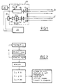
- the device according to the invention represented diagrammatically in FIG. 1, comprises a laser generator 10 emitting a pulse signal transmitted in a direction D by afocal optics 12 making it possible in particular to enlarge the diameter of the beam emitted by the laser generator 10, and reduce its divergence.
- the associated receiver comprises an optic 14, for example a telescope or an afocal optic, the optical axis D 'of which is very close to or substantially coincident with the optical axis D of the transmitter, and a mono-chromatic spectral filtering system , comprising an interference filter 16 with very low bandwidth, followed by an interferometer 18 from Pérot-Fabry centered on a given wavelength.
- This spectral filtering system 16, 18 is followed by a photo-detector 20, the output of which is connected to means 22 for analyzing the intensity of the detected signal, comprising computer calculation means.
- the laser generator 10 can be of the wavelength tunable type, or it consists of a temperature-stabilized laser diode and is then associated with temperature variation means 24, acting on the laser diode to vary correspondingly the central wavelength of the emission spectrum.
- the Pérot-Fabry interferometer 18 can also be equipped with fine adjustment means 26, for example of the piezoelectric type, making it possible to modify the wavelength of the signal transmitted to the photo-detector 20.
- the means 22 essentially constituted by a microcomputer, will also control the operation of the laser generator 10, and that of the aforementioned means 24 and 26.
- the entire optical system can be mounted on a mobile support 28, associated with orientation control means 30, and making it possible, for example, to scan a zone of space by the optical axes D, D ′.
- the laser generator 10 emits in the direction D a pulse signal whose frequency can be between 1 and 1000 Hz approximately, whose wavelength spectrum is known and centered on a wavelength ⁇ e which is for example 800 or 1550 nm when using a laser diode.
- the emission power of the generator 10 is for example 1 mJ per pulse. In the case of a solid laser source, it can exceed 1 J.
- the duration of the pulses is for example 100 ns.
- the laser pulses emitted are partly backscattered by particles in the atmosphere (Rayleigh-Brillouin and / or Mie scattering) and are picked up by the optics 14 of the receiver, to be transmitted to the interference filter 16.
- the latter has a band very low bandwidth, on the order of a nanometer and transmits the signals it receives to the interferometer 18, which is for example centered on the average value of the central wavelength ⁇ e of emission, with an accuracy of l 'order of 10 picometers for example.
- the output signal from the interferometer 18 is transmitted to the photodetector 20, which is for example a germanium photodiode or a photomultiplier tube, depending on the value of the central emission wavelength.
- the means 22 carry out an analysis of the variation as a function of time of the intensity of the output signal from the detector 20.
- This variation of intensity as a function of time corresponds to a variation of the intensity of the signal as a function of the altitude .
- the spectral conditions are then modified (by variation of the central emission wavelength or of the reception wavelength), or the spatial conditions (by variation of an angle ⁇ of the optical axis D, D ′ with respect to a reference system) and we repeat the previous analyzes.
- a meteorological measurement is therefore constituted by the analysis of NxMxL laser pulse emissions, N being a number of identical pulse emissions under given spectral and spatial conditions, M being the number of values which are successively given to the central emission wavelength or the reception wavelength, L being the number of successive directions of observation.
- the duration of such a measurement is determined so that the parameters to be measured can be considered constant for the duration of the measurement (i.e. their fluctuations remain less than the accuracy of the measurement), this measurement time can be of the order of a minute or less for example.
- the measurements are relative and are carried out with respect to backscattered signals at zero altitude.
Landscapes
- Physics & Mathematics (AREA)
- Engineering & Computer Science (AREA)
- Computer Networks & Wireless Communication (AREA)
- Electromagnetism (AREA)
- General Physics & Mathematics (AREA)
- Radar, Positioning & Navigation (AREA)
- Remote Sensing (AREA)
- Optical Radar Systems And Details Thereof (AREA)
- Investigating Or Analysing Materials By Optical Means (AREA)
- Measuring Temperature Or Quantity Of Heat (AREA)
Applications Claiming Priority (2)
| Application Number | Priority Date | Filing Date | Title |
|---|---|---|---|
| FR9007927 | 1990-06-25 | ||
| FR9007927A FR2663752B1 (fr) | 1990-06-25 | 1990-06-25 | Dispositif de mesure de parametres meteorologiques. |
Publications (1)
| Publication Number | Publication Date |
|---|---|
| EP0463914A1 true EP0463914A1 (de) | 1992-01-02 |
Family
ID=9397956
Family Applications (1)
| Application Number | Title | Priority Date | Filing Date |
|---|---|---|---|
| EP91401555A Withdrawn EP0463914A1 (de) | 1990-06-25 | 1991-06-12 | Geräte zur Messung von meteorologischen Parametern |
Country Status (5)
| Country | Link |
|---|---|
| US (1) | US5214484A (de) |
| EP (1) | EP0463914A1 (de) |
| JP (1) | JPH06342084A (de) |
| CA (1) | CA2045244A1 (de) |
| FR (1) | FR2663752B1 (de) |
Families Citing this family (20)
| Publication number | Priority date | Publication date | Assignee | Title |
|---|---|---|---|---|
| US6034760A (en) * | 1997-10-21 | 2000-03-07 | Flight Safety Technologies, Inc. | Method of detecting weather conditions in the atmosphere |
| JP3647696B2 (ja) | 1999-11-22 | 2005-05-18 | 三菱電機株式会社 | 乱流層検出装置 |
| US7106447B2 (en) * | 2002-03-01 | 2006-09-12 | Michigan Aerospace Corporation | Molecular optical air data systems (MOADS) |
| US7495774B2 (en) * | 2002-03-01 | 2009-02-24 | Michigan Aerospace Corporation | Optical air data system |
| DE10316762B4 (de) * | 2003-04-10 | 2007-01-25 | Eads Deutschland Gmbh | Verfahren zur Erfassung von Windgeschwindigkeiten mit einem Doppler-Lidar-System, insbesondere an Bord von Flugzeugen, und Doppler-Lidar-System |
| US7030991B1 (en) | 2003-08-01 | 2006-04-18 | Ball Aerospace & Technologies Corp. | Field condensing imaging system for remote sensing of atmospheric trace gases |
| US7050215B1 (en) | 2003-08-01 | 2006-05-23 | Ball Aerospace & Technologies Corp. | Method and apparatus for providing a gas correlation filter for remote sensing of atmospheric trace gases |
| FR2865545B1 (fr) * | 2004-01-22 | 2006-05-05 | Commissariat Energie Atomique | Lidar compact |
| GB0411097D0 (en) * | 2004-05-19 | 2004-06-23 | Qinetiq Ltd | Laser radar device and method |
| DE102005034729B3 (de) * | 2005-07-21 | 2007-02-08 | Eads Deutschland Gmbh | Verfahren und Lidar-System zur Messung von Luftturbulenzen an Bord von Luftfahrzeugen sowie für Flughäfen und Windfarmen |
| US8958057B2 (en) * | 2006-06-27 | 2015-02-17 | Arete Associates | Camera-style lidar setup |
| WO2010124038A2 (en) * | 2009-04-21 | 2010-10-28 | Michigan Aerospace Corporation | Atmospheric measurement system |
| US8797550B2 (en) | 2009-04-21 | 2014-08-05 | Michigan Aerospace Corporation | Atmospheric measurement system |
| EP2430392B1 (de) * | 2009-05-15 | 2015-07-22 | Michigan Aerospace Corporation | Bereichsabbildungs-lidar |
| US8355120B2 (en) * | 2010-03-10 | 2013-01-15 | The United States Of America, As Represented By The Secretary Of The Navy | Doppler asymmetric spatial heterodyne spectroscopy light detection and ranging receiver |
| FI125286B (fi) * | 2011-07-01 | 2015-08-14 | Teknologian Tutkimuskeskus Vtt Oy | Järjestely ja menetelmä jäätymisen havainnoimiseksi |
| RU2494422C2 (ru) * | 2011-12-29 | 2013-09-27 | Федеральное государственное бюджетное образовательное учреждение высшего профессионального образования "Московский государственный технический университет имени Н.Э. Баумана" (МГТУ им. Н.Э. Баумана) | Лазерный дистанционный способ оценки мгновенной скорости и направления ветра |
| US9933514B1 (en) | 2015-03-12 | 2018-04-03 | The Boeing Company | LADAR systems with dynamic receiver filters |
| US11650294B2 (en) | 2018-03-28 | 2023-05-16 | Murata Manufacturing Co., Ltd. | Fabry-pérot element in lidar device |
| GB202019266D0 (en) * | 2020-12-08 | 2021-01-20 | Lumi Space Ltd | Ground to space laser power delivery method and system |
Citations (5)
| Publication number | Priority date | Publication date | Assignee | Title |
|---|---|---|---|---|
| US3723007A (en) * | 1971-01-22 | 1973-03-27 | Avco Corp | Remote quantitative analysis of materials |
| CA1069725A (en) * | 1977-05-17 | 1980-01-15 | Elmer H. Hara | Clear air turbulence detector |
| DE2924490A1 (de) * | 1978-08-03 | 1980-02-14 | Fruengel Frank Dr Ing | Verfahren und einrichtung zur wolkenhoehenmessung |
| WO1987007018A1 (en) * | 1986-05-15 | 1987-11-19 | Hibshman Corporation | Oxygen measurement using visible radiation |
| GB2215039A (en) * | 1988-02-10 | 1989-09-13 | Plessey Co Plc | Optical absorption gas sensor |
Family Cites Families (5)
| Publication number | Priority date | Publication date | Assignee | Title |
|---|---|---|---|---|
| US5123730A (en) * | 1988-08-09 | 1992-06-23 | The Oregon Graduate Institute Of Science & Technology | Apparatus for optical remote wind sensing |
| FR2640755B1 (fr) * | 1988-12-15 | 1991-03-22 | Crouzet Sa | Anemometre laser a plusieurs directions de mesure |
| FR2648915B1 (fr) * | 1989-06-26 | 1991-09-27 | Centre Nat Rech Scient | Dispositif de mesure de la vitesse du vent a moyenne altitude |
| US5110217A (en) * | 1989-08-01 | 1992-05-05 | Gte Government Systems Corporation | Method for optically and remotely sensing subsurface water temperature |
| US5029999A (en) * | 1989-10-17 | 1991-07-09 | Thermo Electron Technologies Corp. | Laser radar device |
-
1990
- 1990-06-25 FR FR9007927A patent/FR2663752B1/fr not_active Expired - Fee Related
-
1991
- 1991-06-12 EP EP91401555A patent/EP0463914A1/de not_active Withdrawn
- 1991-06-21 CA CA002045244A patent/CA2045244A1/fr not_active Abandoned
- 1991-06-24 US US07/719,803 patent/US5214484A/en not_active Expired - Fee Related
- 1991-06-25 JP JP3181834A patent/JPH06342084A/ja active Pending
Patent Citations (5)
| Publication number | Priority date | Publication date | Assignee | Title |
|---|---|---|---|---|
| US3723007A (en) * | 1971-01-22 | 1973-03-27 | Avco Corp | Remote quantitative analysis of materials |
| CA1069725A (en) * | 1977-05-17 | 1980-01-15 | Elmer H. Hara | Clear air turbulence detector |
| DE2924490A1 (de) * | 1978-08-03 | 1980-02-14 | Fruengel Frank Dr Ing | Verfahren und einrichtung zur wolkenhoehenmessung |
| WO1987007018A1 (en) * | 1986-05-15 | 1987-11-19 | Hibshman Corporation | Oxygen measurement using visible radiation |
| GB2215039A (en) * | 1988-02-10 | 1989-09-13 | Plessey Co Plc | Optical absorption gas sensor |
Non-Patent Citations (2)
| Title |
|---|
| APPLIED OPTICS. vol. 7, no. 3, 1 Février 1988, NEW YORK US pages 441 - 443; SCHOTLAND ET AL: 'CONCEPTUAL TEST OF FREQUENCY DIVERSITY LIDAR ' * |
| PROCEEDINGS OF THE IEEE. vol. 77, no. 3, Mars 1989, NEW YORK US pages 408 - 409; GARDNER: 'SODIUM RESONACE FLUORESCENCE LIDAR APPLICATIONS IN ATMOSPHERIC SCIENCE AND ASTRONOMY ' * |
Also Published As
| Publication number | Publication date |
|---|---|
| FR2663752B1 (fr) | 1993-01-22 |
| FR2663752A1 (fr) | 1991-12-27 |
| CA2045244A1 (fr) | 1991-12-26 |
| US5214484A (en) | 1993-05-25 |
| JPH06342084A (ja) | 1994-12-13 |
Similar Documents
| Publication | Publication Date | Title |
|---|---|---|
| EP0463914A1 (de) | Geräte zur Messung von meteorologischen Parametern | |
| EP0406058B1 (de) | Vorrichtung zur Windgeschwindigkeitsmessung in mittleren Höhen | |
| EP1779137B1 (de) | Optische einrichtung zur messung einer doppler-frequenzverschiebung | |
| EP0173617B1 (de) | Sender-Empfängersysteme für Laserbilderzeugung | |
| FR2669115A1 (fr) | Systeme radar en ondes millimetriques pour le guidage d'un robot mobile au sol. | |
| WO2002095475A1 (fr) | Procede et dispostif de mesure par imagerie confocale a chromatisme entendu | |
| EP1183518B1 (de) | Vorrichtung zur bestimmung der werte mindestens eines teilchenparameters, insbesondere von wassertröpfchen | |
| EP0942293B1 (de) | Vorrichtung zur Messung von Abstand oder Einfallswinkel eines Lichtstrahls | |
| EP1932001B1 (de) | Optische einrichtung zur messung der bewegungsgeschwindigkeit eines objekts relativ zu einer oberfläche | |
| EP1084379B1 (de) | Optoelektronische Formerfassung durch chromatische Kodierung mit Beleuchtungsebenen | |
| EP0241374B1 (de) | Optronische Abweichungsvorrichtung zur räumlichen und spektralen Erkennung von infraroten Lichtquellen | |
| WO2012080372A1 (fr) | Dispositif actif d'observation d'une scène à travers un milieu diffusant, utilisation de ce dispositif et procédé d'observation | |
| EP1927001B1 (de) | Laservorrichtung zum messen der luftgeschwindigkeit mit verbesserter augensicherheit | |
| EP1105712B1 (de) | Messvorrichtung der grösse sich bewegender teilchen, insbesondere für regenmessungen | |
| EP0561680B1 (de) | Vorrichtung zum Messen der axialen Geschwindigkeit | |
| FR3118197A1 (fr) | Lidar cohérent à modulation de fréquence amélioré | |
| EP0528702B1 (de) | Abbildungssystem mit integrierter Abnutzungsmessung der in Transmission arbeitenden optischen Elemente und optronische Abbildungseinrichtung, bestehend aus solch einem Abbildungssystem | |
| FR3013843A1 (fr) | Dispositif et procede de determination de presence de degradations ou salissures sur un hublot de sonde d'anemometrie laser doppler | |
| EP0246130A1 (de) | Detektor zur kontaktlosen linearen Messung der Entfernung eines Objektes mittels rückgestreuter Strahlung | |
| EP0036370B1 (de) | Verfahren und Vorrichtung zum Messen der Sichtweite | |
| FR2614100A1 (fr) | Procede et dispositif de mesure par reflexion du coefficient de transmission optique d'une paroi vitreuse teintee | |
| FR2677456A1 (fr) | Systeme laser a detection heterodyne avec reduction des effets de la lumiere parasite. | |
| FR2769710A1 (fr) | Appareil de mesure de longueur d'onde pour impulsions lasers courtes | |
| FR3139391A1 (fr) | Systeme lidar pour mesures velocimetriques | |
| FR2757953A1 (fr) | Appareil de mesure de vitesse |
Legal Events
| Date | Code | Title | Description |
|---|---|---|---|
| PUAI | Public reference made under article 153(3) epc to a published international application that has entered the european phase |
Free format text: ORIGINAL CODE: 0009012 |
|
| AK | Designated contracting states |
Kind code of ref document: A1 Designated state(s): AT BE CH DE DK ES FR GB GR IT LI LU NL SE |
|
| 17P | Request for examination filed |
Effective date: 19920622 |
|
| 17Q | First examination report despatched |
Effective date: 19940307 |
|
| STAA | Information on the status of an ep patent application or granted ep patent |
Free format text: STATUS: THE APPLICATION IS DEEMED TO BE WITHDRAWN |
|
| 18D | Application deemed to be withdrawn |
Effective date: 19941230 |