EP0463929A1 - Mechanisches Gelenkträgerelement insbesondere für ein Episkop, und Episkop, das auf ein solches Trägerelement montiert wird - Google Patents
Mechanisches Gelenkträgerelement insbesondere für ein Episkop, und Episkop, das auf ein solches Trägerelement montiert wird Download PDFInfo
- Publication number
- EP0463929A1 EP0463929A1 EP91401631A EP91401631A EP0463929A1 EP 0463929 A1 EP0463929 A1 EP 0463929A1 EP 91401631 A EP91401631 A EP 91401631A EP 91401631 A EP91401631 A EP 91401631A EP 0463929 A1 EP0463929 A1 EP 0463929A1
- Authority
- EP
- European Patent Office
- Prior art keywords
- episcope
- reflector
- light rays
- frame according
- repositioning
- Prior art date
- Legal status (The legal status is an assumption and is not a legal conclusion. Google has not performed a legal analysis and makes no representation as to the accuracy of the status listed.)
- Withdrawn
Links
- 230000004438 eyesight Effects 0.000 claims abstract description 23
- 230000007935 neutral effect Effects 0.000 claims abstract description 15
- 230000003287 optical effect Effects 0.000 claims description 21
- 230000005540 biological transmission Effects 0.000 claims description 6
- 230000004297 night vision Effects 0.000 claims description 5
- 238000006073 displacement reaction Methods 0.000 claims description 2
- 230000007704 transition Effects 0.000 description 6
- 230000008859 change Effects 0.000 description 5
- 230000000903 blocking effect Effects 0.000 description 2
- 230000006866 deterioration Effects 0.000 description 2
- 210000003128 head Anatomy 0.000 description 2
- 238000012423 maintenance Methods 0.000 description 2
- 239000000463 material Substances 0.000 description 2
- 238000000034 method Methods 0.000 description 2
- 230000002441 reversible effect Effects 0.000 description 2
- 238000012800 visualization Methods 0.000 description 2
- 241000287107 Passer Species 0.000 description 1
- 230000009471 action Effects 0.000 description 1
- 230000003213 activating effect Effects 0.000 description 1
- 230000000721 bacterilogical effect Effects 0.000 description 1
- 239000013013 elastic material Substances 0.000 description 1
- 229940020445 flector Drugs 0.000 description 1
- 210000001061 forehead Anatomy 0.000 description 1
- 238000010438 heat treatment Methods 0.000 description 1
- 238000002649 immunization Methods 0.000 description 1
- 230000003053 immunization Effects 0.000 description 1
- 239000004973 liquid crystal related substance Substances 0.000 description 1
- 230000014759 maintenance of location Effects 0.000 description 1
- 238000004519 manufacturing process Methods 0.000 description 1
- 230000007246 mechanism Effects 0.000 description 1
- 230000008569 process Effects 0.000 description 1
- 230000009467 reduction Effects 0.000 description 1
- 238000009877 rendering Methods 0.000 description 1
- 238000007789 sealing Methods 0.000 description 1
- 239000007787 solid Substances 0.000 description 1
- 239000000126 substance Substances 0.000 description 1
- 238000010257 thawing Methods 0.000 description 1
Images


Classifications
-
- F—MECHANICAL ENGINEERING; LIGHTING; HEATING; WEAPONS; BLASTING
- F41—WEAPONS
- F41H—ARMOUR; ARMOURED TURRETS; ARMOURED OR ARMED VEHICLES; MEANS OF ATTACK OR DEFENCE, e.g. CAMOUFLAGE, IN GENERAL
- F41H5/00—Armour; Armour plates
- F41H5/26—Peepholes; Windows; Loopholes
- F41H5/266—Periscopes for fighting or armoured vehicles
-
- G—PHYSICS
- G02—OPTICS
- G02B—OPTICAL ELEMENTS, SYSTEMS OR APPARATUS
- G02B23/00—Telescopes, e.g. binoculars; Periscopes; Instruments for viewing the inside of hollow bodies; Viewfinders; Optical aiming or sighting devices
- G02B23/02—Telescopes, e.g. binoculars; Periscopes; Instruments for viewing the inside of hollow bodies; Viewfinders; Optical aiming or sighting devices involving prisms or mirrors
- G02B23/08—Periscopes
-
- G—PHYSICS
- G02—OPTICS
- G02B—OPTICAL ELEMENTS, SYSTEMS OR APPARATUS
- G02B23/00—Telescopes, e.g. binoculars; Periscopes; Instruments for viewing the inside of hollow bodies; Viewfinders; Optical aiming or sighting devices
- G02B23/12—Telescopes, e.g. binoculars; Periscopes; Instruments for viewing the inside of hollow bodies; Viewfinders; Optical aiming or sighting devices with means for image conversion or intensification
-
- G—PHYSICS
- G02—OPTICS
- G02B—OPTICAL ELEMENTS, SYSTEMS OR APPARATUS
- G02B23/00—Telescopes, e.g. binoculars; Periscopes; Instruments for viewing the inside of hollow bodies; Viewfinders; Optical aiming or sighting devices
- G02B23/16—Housings; Caps; Mountings; Supports, e.g. with counterweight
Definitions
- the field of the invention is that of episcopic vision.
- the invention relates to a frame particularly suitable for an episcope allowing two distinct processing modes of the light rays received, which can in particular be used for day vision with conventional optical means, and for night vision, for example by means of a light intensifier tube.
- the invention relates to mechanical means simplifying and optimizing the transition from one vision mode to another.
- the invention also relates to an episcope mounted on such a frame.
- the invention finds particular application in observation equipment for armored vehicles, and in particular for combat tanks. More generally, the episcope of the invention can be used in all cases where it is necessary to isolate the observer from the observed field and where it is useful to have two types of optical and / or electronic processing of light rays received by the episcope, comprising for example on the one hand means of direct vision by optical means, and on the other hand by electronic display means, such as a light intensifier, an infrared detector or a camera, with CCD sensor or other.
- electronic display means such as a light intensifier, an infrared detector or a camera, with CCD sensor or other.
- the pilot generally has, for day vision, at least one conventional optical episcope, called day track, comprising an input reflector receiving the light rays, and an output reflector rendering the light rays to the pilot.
- the path of the light rays between the two reflectors can be direct or undergo one or more reflections.
- the daytime channel provides optimal vision, as long as there is sufficient light. However, it does not allow piloting at night. It is in fact not possible, at least in the combat position, to use lighting means integrated into the vehicle. It is therefore necessary to use an electronic night track, restoring to the pilot a visible image of the landscape, and comprising for example a objective, a light intensifier tube and an eyepiece.
- Another problem posed by this technique is the storage of the unused episcope in the passenger compartment of the vehicle, in which the space is most often very limited. In addition, this unused episcope runs great risks of deterioration, if it is not properly secured.
- day-night episcopes comprising in a single housing a conventional day channel and a night channel with light intensifier.
- the French patent application documents 85 02575 and 85 02576, deposited on 02.22.1985 present episcopes with day and night channels substantially parallel and placed one behind the other, the input reflector being mobile, and directing the light rays towards one of the two channels, according to the position selected by the pilot.
- Armored vehicles generally have three daytime periscopes, allowing the driver to see from the front and from the sides. However, for reasons cost and space, it is not possible to use three devices for night vision. Thus, only the front episcope is removable and can be replaced by a night episcope. In order to widen the pilot's field of vision, it was imagined to pivot this night-time episcope into a bearing.
- the transition from the daytime track to the night track is silenced by moving a movable reflector.
- this reflector does not interfere with the light rays, which are directly received by the daylight track.
- the reflector deflects the light rays towards the night track.
- This night track comprising the movable reflector, a lens, a light intensifier tube and a biocular can then turn into a deposit.
- This double repositioning operation then retraction poses several problems.
- the pilot risks forgetting the first repositioning step, and directly activating the command to change from the night lane to the day lane. There will then be forcing of the mechanics and, possibly, deterioration of the material.
- the lack of instantaneity of the lane change, due to the prior repositioning, can prove to be harmful, especially in combat situations.
- the invention particularly aims to overcome these various drawbacks.
- the invention thus relates to an episcope making it possible to process the light rays received according to two distinct processing modes, one of the modes offering an enlarged field of vision, by means of a device which can pivot in bearing.
- An objective of the invention is to provide a frame for such an episcope, allowing the passage from one mode of treatment of light rays to another in a simple, safe and rapid manner.
- the invention aims to provide such a frame allowing the observer to switch from one to the other of the treatment modes using a single and simple command, whatever the position of the device. swivel.
- the invention also aims to provide such a frame, in which the transition from one treatment mode to another takes place almost instantaneously. In other words, there must be no downtime, during which the vehicle is blind, so as to make it possible in particular to change numerous treatment modes, in particular in the case of intermediate lighting.
- Another objective of the invention is to provide an episcope, as solid and reliable as possible, while avoiding any possibility of forcing by the user, and by using only mechanical means.
- the invention also aims to provide such an episcope, having a limited overall size. Indeed, space is very limited in armored vehicles. Furthermore, the reduced size of the episcope must allow its use in several types of vehicles.
- a particular objective of the invention is to provide such an easily removable and modular episcope, in particular as regards the two devices for processing light rays.
- an articulated mechanical frame in particular for an episcope, of the type used in an armored vehicle, comprising a retractable reflector, movable between two extreme positions, allowing in a first retracted position the free circulation of the light rays received in the direction of a first optical and / or electronic processing device of said light rays, and in a second position activates the deflection of said light rays in the direction of a second device for optical and / or electronic processing of said light rays which can pivot in bearing so as to widen the field of vision, comprising means for automatic repositioning of said second device which can be pivoted in a neutral position, allowing said retractable reflector to be retracted , said repositioning means being slaved to means for retracting said re retractable flector.
- a single command allows the repositioning of the pivotable device and the retraction of the reflector. Furthermore, there is no risk of forcing a retraction control when the pivotable device is not in its rest position.
- said retractable reflector can switch between two extreme positions defining an angle of approximately ⁇ / 2.
- said retraction means comprise means for guiding the travel of movement of said reflector consisting of a fin, of generally semi-circular shape, comprising a circumferential groove for receiving and guiding a spike secured to the support of said support retractable reflector.
- the rotational movement of said retractable reflector is actuated by a set of at least two articulated links, a first link having its free end rotatably mounted on the support of said reflector, and a second rod having its free end driven in rotation by means of transmission of a movement actuated by the selection control of one of said devices.
- At least one of said links has at least one curvature, so as to limit the overall size of said episcope.
- the three axes of rotation corresponding to the ends of said rods lie substantially in the same plane, when said retractable reflector is in said active position.
- said means for transmitting a movement comprise a rotation rod substantially parallel to said display devices, and integral with a control lever for selecting one of said optical and / or electronic processing devices , the rotational movement of which is transmitted to said second link by gear.
- the frame according to the invention comprises means for closing said second optical and / or electronic processing device when said reflector is in the retracted position, cooperating with said retracting means.
- the second pivotable device comprises processing means such as a light intensifier tube, to close it when it is not in use.
- said closure means are constituted by one of said links.
- said repositioning means comprise at least one repositioning link, one of the ends of which is secured to said second pivotable device comprising a slide, in which a pin secured to retracting control means can slide, so that the retracting operation of said retractable reflector simultaneously causes the repositioning of said second device in said neutral position.
- each of said pins is mounted eccentrically between two plates integral with the rod for transmitting the rotational movement of said control lever, so as to form a kind of crankshaft.
- said repositioning means comprise an indexing roller of said second device in said neutral position, said roller being mounted on the frame and pushed elastically, so as to cooperate with a receiving notch formed in said second pivotable device, when said second device is in neutral position.
- This roller allows the pilot in particular to feel tactfully that the pivotable device is in its neutral position, which advantageously corresponds to the central position.
- the frame comprises at least one return tension spring in the two extreme positions of said second pivotable device.
- the invention also relates to an episcope mounted in a frame having at least some of the preceding characteristics.
- the episcope comprises means for securing in rotation said retractable reflector in active position with the eyepiece of said second pivotable device, the intermediate means of optical and / or electronic processing of said second device being fixed.
- said retraction means advantageously actuate means for switching on and off said electronic processing means.
- said first light ray processing device is an optical device, based on reflectors.
- Said second pivotable device can in particular be a vision device for night, including a lens, an intensifier tube and a biocular.
- said second pivotable device can advantageously comprise a camera sensor and a display screen.
- these devices are preferably placed in independent boxes.
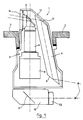
- FIG. 1 represents a vertical section of the optical components of an episcope capable of incorporating an articulated frame according to the present invention.
- An episcope 1 crosses the armor 2 of a vehicle.
- the episcope 1 comprises two independent episcopic devices 3 and 4 juxtaposed.
- the light rays received by the upper part of the episcope 1 are directed either towards the arrangement 3, called night path, or towards the device 4, called day path, according to the position of a retractable reflector 5.
- This reflector can including being a mirror or a triangular prism.
- the retractable reflector 5 When the light rays are of sufficient intensity, the retractable reflector 5 is folded down so that the light rays pass directly into the daytime track 4.
- the first device 4 can comprise two reflectors 6 and 12 reflecting the light signals entering the episcope towards an observer 7, typically an armored vehicle operator.
- the light signals coming from the outside are reflected by the reflector 12 towards the reflector 6 which sends them to the observer 7.
- the first device 4 may also include one or more objectives for processing the light signal or else electronic processing means (sensors, CCD camera or the like).
- the episcope When the episcope is operating in day mode, that is to say when the rays are admitted into the device 4, the episcope is stationary in rotation. It is not necessary to be able to turn the daytime track into a deposit since known armored vehicles generally comprise two lateral daytime periscopes.
- the transition from the daytime track to the night track is effected by tilting the retractable reflector 5 above the night track 3.
- the light rays admitted into the episcope are directed towards the second treatment device 3 and no longer reach day 4 track.
- the night track 3 is constituted, in the configuration of FIG. 1, of an objective 8, of a light intensifier tube 9 and of a biocular 10.
- the objective 8 and the light intensifier tube 9 are juxtaposed in channel 3.
- the biocular 10 comprises a reflector 11 and optical processing means, not shown, making it possible to obtain an image visible by both eyes at the exit of the biocular.
- the night track 3 can also consist of infrared, CCD or other sensors or devices for processing a light signal.
- the intensifier tube 9 can be replaced by a camera sensor and the biocular 10 by a display screen.
- the observer 7 can control the deposit of the night track, i.e. its rotation around a vertical axis.
- the objective 8 and the intensifier tube 9 advantageously remain stationary, only the retractable reflector 5 and the biocular 10 being free to rotate. This reduces the overall size of the episcope.
- the two ways of processing the light rays are fixed in independent boxes, linked to each other for example by screwing. These two assembled housings constitute the watertight envelope of the episcope.
- the exterior part of the vehicle remains fixed, which makes it possible to ensure, in a simple manner, the seal between the episcope and the shielding of the housing from the absence of a rotating part at this level.
- the modularity of the two treatment paths has many advantages. This allows on the one hand to realize a common night route for several types of episcopes that can take place in different types of armored vehicles, only the day route and the housing of the episcope to be adapted.
- This window 14 can advantageously include means for defrosting, for example by resistive dielectric treatment.
- the eyepiece 53 may have defogging means, constituted for example by a heating resistor.
- a forehead support (not shown) which can occupy a "day” position and a “night” position ensures in the night position the mechanical protection of the lower prism 6 by day and the closure of the day channel 4, preventing any light leak from inside to outside of the tank.
- Figure 2 is a vertical sectional view of a model illustrating an advantageous embodiment of the frame of the invention in the so-called “active" position ("night track” position in the case of its use in an episcope);
- the tilting of the movable reflector 5 is controlled by circular movement of a control handle 20 for selecting one of the devices 3 and 4 (fig.1).
- the lever 20 can take two extreme positions thanks to return means not shown.
- the control lever 20 is connected to a transmission rod 21 secured to a plate 22.
- Above the plate 22 are arranged two other plates 24 and 26 spaced apart by pins 23 and 25 forming cranks.
- the pins 23 and 25 are fixed in an eccentric position relative to an axis passing through the transmission rod and the centers of the three plates 22, 24 and 26, respectively between the plates 22, 24 and 24, 26, so as to form a kind of crankshaft.
- the upper plate 26 is also integral with a rotation rod 27 substantially parallel to the display devices 3 and 4.
- the rotation rod 27 is provided with a frustoconical pinion 28 at its upper end.
- Another frustoconical pinion 29 is mounted free to rotate perpendicularly to the pinion 28 on a support 30, forming a gear.
- a link 31 is fixed integrally to the frustoconical pinion 29 and its other end is fixed to a bent link 32.
- the other end of the link 32 is mounted to rotate freely on a support 33 of the retractable reflector 5 movable in rotation.
- the support 33 of the reflector 5 is disposed above the objective 8 of the night track, so that the reflector 5, in the active position shown, transmits the light rays towards the objective 8.
- the support 33 consists of a fixed part 44 connected to the link 32 and a mobile part 43 free to rotate relative to the fixed part 44.
- the reflector 5 is fixed integrally to the mobile part 43 so as to being able to pivot in bearing about the axis 49, when it is in the "active" non-tilted position, of FIG. 2.
- the fixed part 44 of the support 33 is integral with a set of two symmetrical fixing lugs 45 (only one of which is visible in the figure).
- the legs 45 are movable in rotation about an axis 42 between two extreme positions so as to cause the reflector 5 to tilt between the "active" position and the "retracted” position.
- a set of two stops 46 (only one of which is shown) are used for good positioning and good immobilization at the end of the travel of the reflector 5 by coming into contact with the front part of each of the legs 45.
- shims 47 made of elastic material, such as rubber, are placed on the stops 46.
- an alignment of the three axes of rotation passing through the ends of the rods 31 and 32 in the same plane 48 ensures good immunization of the device to vibrations.
- the mobile part 43 is provided with a pin 34 which can move in guide means 35.
- These guide means advantageously consist of a semi-circular fin with circumferential groove for receiving the pin 34.
- the upper end of the the fin is secured to a ring 41 which can pivot around the objective 8 located under the support 33.
- the inner end of the fin 35 is fixedly attached to a rod 36 secured to a plate 37.
- the plate 37 is advantageously of circular shape and shape of the biocular fixing plate 10. Thanks to this connection system, any rotation of the plate 37 (to which the biocular 10 is fixed) causes the upper reflector 5 to rotate, via the rod 36, the fin 35 and the ring 41 linked to the movable part 43.
- Another mode of implementation consists in fixing the inner end of the rod 36 directly on the biocular 10.
- the pins 23 and 25 serve as guide axes for repositioning links 38 and 39 each comprising an oblong slot forming a slide.
- Each link is rotatably mounted on the plate 37 at one of its ends, or on the biocular 10, depending on the embodiment chosen.
- the biocular 10 is integral with a control arm 40 allowing the device shown to pivot in bearing.
- the hatched elements 70 represent the fixed part of the frame.
- the rotation of the rotation rod 27 causes that of the gear formed by the frustoconical pinions 28 and 29.
- the rotation of the frustoconical pinion 29 in the trigonometric direction causes the rotation in the same direction of the retraction rod 31.
- This rotation causes the advance of the rod 32 in the direction of the objective 8 and causes the support 33 and the reflector 5 around the axis 42, the guide of the movable part 43 of the support 33 being ensured by the retention of the pin 34 in the semi-circular fin 35 with circumferential receiving groove.
- the retraction carried out allows the passage of the light rays towards the other processing path, in particular the day path in the embodiment described, since the night path is arranged between the entry of the light rays into the episcope and the day track.
- the reflector When the reflector is in its extreme low position, it is said to be in the retracted position, that is to say that it no longer reflects the light rays.
- a rotation of the lever 20 in the opposite direction makes it possible to reposition the reflector in the active position.
- the rotation in bearing is controlled manually by rotation of the control arm 40.
- This control arm 40 is fixed either directly to the biocular 10, as shown in FIG. 2, or to the plate 37 for holding the biocular 10.
- the rotation of the control arm 40 causes that of the semi-circular fin 35 fixed to the ring 41 free to rotate around the fixed objective 8.
- the pin 34 being engaged in the semi-circular fin 35 and integral with the mobile part in rotation 43 on which the reflector 5 is arranged, allows the rotation of the reflector 5. Since the transmission produced is "direct", the reflector 5 rotates at the same angle as the biocular 10.
- This device therefore allows the observer located in the armored vehicle to visualize a whole field around him at night.
- the field covered is approximately 110 °, thanks to the bearing rotation of ⁇ 30 ° around the neutral position.
- the retracting means of the reflector 5 constituted by the plates 22, 24, 26, the rotation rod 27, the pinions 28, 29, the rods 31, 32 and the fixed part 44 of the support 33 remain stationary during actuation of the control arm 40, by sliding the pins 23 and 25 in the repositioning links 38 and 39, one end of which is secured to the plate 37 or to the upper surface of the biocular 10.
- the extreme positions of the track at night are reached when the repositioning links 38, 39 come into abutment against the pins 25 and 23 respectively.
- One of the main characteristics of the present invention resides in the fact that the passage from the night lane to the day lane is carried out automatically, by simple actuation of the control lever 20 to switch to the day lane, whatever the position in reflector field 5.
- the transition from the daytime track to the nighttime track automatically activates the electronic means, and in particular the intensifier tube, for example by means of a micro-contact.
- FIG. 3 is a top view of the automatic repositioning means in the frame of the frame of FIG. 2.
- the reflector is in the so-called neutral position, for example immediately after changing from the day position to the night position, without there has been action on the control arm 40.
- the plate 24 separating the pins 23 and 25 is not shown for reasons of convenience of understanding.
- the pins 23 and 25 are located on the side of the biocular 10, substantially equal distance on either side of an axis 55 passing through the center of the biocular 10.
- the repositioning links 38 and 39 provided with slides respectively comprising the pins 25 and 23 forming a crank present between them a substantially right angle.
- the non-free ends of the links 38 and 39 are fixed to rotation on the support 37 of the biocular 10.
- the support 37 advantageously has a receiving notch 54 into which is inserted a movable pin 50 of reversible blocking mounted on a tension spring 51 of return integral with a support 52 mounted on the frame, when the device is in the position of neutral.
- the automatic repositioning mechanism of the reflector 5 operates when, in the night position, the device is not in the neutral position, that is to say that the movable pin 50 of reversible blocking is out of the notch receiving 54.
- one of the pins 23 or 25 then approached the free end of its link while the other moved away from the free end of its own, in the direction 56 of movement of the control arm 40.
- the rotation of the control lever 20 to switch to day display causes the rotation of the plate 37 and of the biocular 10 by bringing one of the pins 23 or 25 into abutment against the free end of a slide of one of the repositioning links.
- the rotation of the lever 20 also causes the rotation of the rod 27 and therefore the pivoting of the reflector 5 around the axis 42, at the same time as its repositioning in the retracted position by rotation of the movable part 43 of the support 33. Repositioning of the reflector 5 is permitted by engagement of the pin 34 in the semi-circular fin 35 which moves integrally with the plate 37 (or with the biocular 10).
- the indexing roller 50 enters the notch 54 of the plate 37 or of the biocular 10 and the repositioning links are at again in the position of FIG. 3.
- the pins 23 and 25 are on the other hand in an opposite position on the plates 22 and 24, with respect to an axis passing through the center of the plates and perpendicular to the axis 55.
- Figure 4 is a perspective view of the frame of Figure 2 in the so-called retracted position ("day track").
- the repositioning links 38 and 39 are substantially perpendicular to each other and their guide pins are in positions opposite to those shown in FIG. 3, the rotation rod and the crankshaft 22, 23, 24, 25 and 26 having turned from ⁇ .
- the retracted position of the reflector 5 shown simultaneously ensures, on the one hand, the total clearance of the passage of the light rays in direction 60 in the daytime track, and on the other hand the obturation of the objective 8 by the link 32.
- the reflector 5 is in the retracted position and the displacement of the links 31 and 32 is calculated such that it requires only a reduced clearance space.
- the fact of using at least one link 32 having a curvature makes it possible to reduce this clearance. Furthermore, the shape of this link allows the objective 8 to be completely closed.
Landscapes
- Physics & Mathematics (AREA)
- Astronomy & Astrophysics (AREA)
- General Physics & Mathematics (AREA)
- Optics & Photonics (AREA)
- Engineering & Computer Science (AREA)
- General Engineering & Computer Science (AREA)
- Telescopes (AREA)
- Instruments For Viewing The Inside Of Hollow Bodies (AREA)
- Stroboscope Apparatuses (AREA)
Applications Claiming Priority (2)
| Application Number | Priority Date | Filing Date | Title |
|---|---|---|---|
| FR9007838 | 1990-06-22 | ||
| FR9007838A FR2663759B1 (fr) | 1990-06-22 | 1990-06-22 | Bati mecanique articule, notamment pour episcope, et episcope monte sur un tel bati. |
Publications (1)
| Publication Number | Publication Date |
|---|---|
| EP0463929A1 true EP0463929A1 (de) | 1992-01-02 |
Family
ID=9397898
Family Applications (1)
| Application Number | Title | Priority Date | Filing Date |
|---|---|---|---|
| EP91401631A Withdrawn EP0463929A1 (de) | 1990-06-22 | 1991-06-18 | Mechanisches Gelenkträgerelement insbesondere für ein Episkop, und Episkop, das auf ein solches Trägerelement montiert wird |
Country Status (5)
| Country | Link |
|---|---|
| EP (1) | EP0463929A1 (de) |
| KR (1) | KR930701759A (de) |
| CA (1) | CA2085988A1 (de) |
| FR (1) | FR2663759B1 (de) |
| WO (1) | WO1992000541A1 (de) |
Cited By (3)
| Publication number | Priority date | Publication date | Assignee | Title |
|---|---|---|---|---|
| GB2260422A (en) * | 1991-10-09 | 1993-04-14 | Israel State | Forward looking infrared viewing apparatus |
| FR2784757A1 (fr) * | 1998-10-19 | 2000-04-21 | Giat Ind Sa | Dispositif pour l'observation jour/nuit a partir d'un vehicule |
| FR2803917A1 (fr) * | 2000-01-19 | 2001-07-20 | Giat Ind Sa | Dispositif de vision jour/nuit |
Families Citing this family (1)
| Publication number | Priority date | Publication date | Assignee | Title |
|---|---|---|---|---|
| US7154283B1 (en) | 2006-02-22 | 2006-12-26 | Avery Dennison Corporation | Method of determining performance of RFID devices |
Citations (4)
| Publication number | Priority date | Publication date | Assignee | Title |
|---|---|---|---|---|
| LU41874A1 (de) * | 1962-06-13 | 1963-12-13 | ||
| US3782808A (en) * | 1973-02-12 | 1974-01-01 | Messerschmitt Boelkow Blohm | Device for arresting the elevation aiming motion of a periscope |
| EP0192309A1 (de) * | 1985-02-22 | 1986-08-27 | Telecommunications Radioelectriques Et Telephoniques T.R.T. | Tag-Nacht-Sichtgerät |
| EP0193236A1 (de) * | 1985-02-22 | 1986-09-03 | Telecommunications Radioelectriques Et Telephoniques T.R.T. | Tag-Nachtsichtgerät mit weitem Sehfeld |
-
1990
- 1990-06-22 FR FR9007838A patent/FR2663759B1/fr not_active Expired - Lifetime
-
1991
- 1991-06-07 WO PCT/FR1991/000454 patent/WO1992000541A1/fr not_active Ceased
- 1991-06-07 CA CA002085988A patent/CA2085988A1/en not_active Abandoned
- 1991-06-07 KR KR1019920703305A patent/KR930701759A/ko not_active Withdrawn
- 1991-06-18 EP EP91401631A patent/EP0463929A1/de not_active Withdrawn
Patent Citations (4)
| Publication number | Priority date | Publication date | Assignee | Title |
|---|---|---|---|---|
| LU41874A1 (de) * | 1962-06-13 | 1963-12-13 | ||
| US3782808A (en) * | 1973-02-12 | 1974-01-01 | Messerschmitt Boelkow Blohm | Device for arresting the elevation aiming motion of a periscope |
| EP0192309A1 (de) * | 1985-02-22 | 1986-08-27 | Telecommunications Radioelectriques Et Telephoniques T.R.T. | Tag-Nacht-Sichtgerät |
| EP0193236A1 (de) * | 1985-02-22 | 1986-09-03 | Telecommunications Radioelectriques Et Telephoniques T.R.T. | Tag-Nachtsichtgerät mit weitem Sehfeld |
Cited By (7)
| Publication number | Priority date | Publication date | Assignee | Title |
|---|---|---|---|---|
| GB2260422A (en) * | 1991-10-09 | 1993-04-14 | Israel State | Forward looking infrared viewing apparatus |
| US5313063A (en) * | 1991-10-09 | 1994-05-17 | State Of Israel Ministry Of Defense Armament Development Authority Rafael | Foldable optical apparatus |
| GB2260422B (en) * | 1991-10-09 | 1995-03-08 | Israel State | Foldable optical apparatus |
| FR2784757A1 (fr) * | 1998-10-19 | 2000-04-21 | Giat Ind Sa | Dispositif pour l'observation jour/nuit a partir d'un vehicule |
| EP0996019A1 (de) * | 1998-10-19 | 2000-04-26 | Giat Industries | Vorrichtung zur Tag -Nacht -Beobachtung von einem Fahrzeug aus |
| FR2803917A1 (fr) * | 2000-01-19 | 2001-07-20 | Giat Ind Sa | Dispositif de vision jour/nuit |
| EP1118895A1 (de) * | 2000-01-19 | 2001-07-25 | Giat Industries | Tag- und Nachtsichtgerät |
Also Published As
| Publication number | Publication date |
|---|---|
| FR2663759B1 (fr) | 1992-09-11 |
| CA2085988A1 (en) | 1991-12-23 |
| FR2663759A1 (fr) | 1991-12-27 |
| WO1992000541A1 (fr) | 1992-01-09 |
| KR930701759A (ko) | 1993-06-12 |
Similar Documents
| Publication | Publication Date | Title |
|---|---|---|
| EP1985913B1 (de) | Kraftfahrzeugscheinwerfer, der ein optisches Modul mit einer beweglichen Blende umfasst | |
| EP0309341B1 (de) | Endgerät für audiovisuelle Kommunikation, insbesondere Videophon mit scharnierendem Gehäuse | |
| EP1505334A1 (de) | Stabilisiertes Plattform-system | |
| WO2022128061A1 (fr) | Boite a illumination homogene pour imagerie photographique ou par camera | |
| FR2709352A1 (fr) | Barillet d'objectif zoom. | |
| EP0193236B1 (de) | Tag-Nachtsichtgerät mit weitem Sehfeld | |
| EP0192309B1 (de) | Tag-Nacht-Sichtgerät | |
| EP0463929A1 (de) | Mechanisches Gelenkträgerelement insbesondere für ein Episkop, und Episkop, das auf ein solches Trägerelement montiert wird | |
| EP0127914B1 (de) | Bilddrehungsfreies Panoramasichtgerät mit mehreren Gesichtsfeldern | |
| EP3238992B1 (de) | Drehbares leuchtmodul | |
| FR2509941A1 (fr) | Appareil de prise de vues pour cinematographie electronique | |
| FR2530009A1 (fr) | Appareil de visee panoramique stabilisee comprenant un detecteur thermique | |
| EP0065457B1 (de) | Periskop für U-Boote mit mehreren Beobachtungsköpfen | |
| EP0459885B1 (de) | Kompakt-Mehrzweckepiskop | |
| EP0703481B1 (de) | Tag-Nacht Episkop | |
| EP3755966B1 (de) | Schutzvorrichtung für einen ausrichtbaren sucher | |
| FR2509034A1 (fr) | Viseur periscopique protege | |
| EP0908752B1 (de) | Vorrichtung zur Beobachtung durch eine Wand eines Schutzgehäuses mit einem Episkop | |
| EP1118895B1 (de) | Tag- und Nachtsichtgerät | |
| FR2680266A1 (fr) | Systeme de restitution de l'environnement visuel d'un pilote en simulateur. | |
| EP1559609A1 (de) | Anzeigegerät für ein Kraftfahrzeug | |
| EP0057154A1 (de) | Abblendbarer Rückspiegel | |
| EP0359634A1 (de) | Periskop zum Tag- und Nachtbetrieb für Panzerfahrzeuge | |
| EP3553585A1 (de) | Head-up anzeigesystem | |
| CA3046695C (fr) | Appareil de visee pour vehicule et vehicule associe |
Legal Events
| Date | Code | Title | Description |
|---|---|---|---|
| PUAI | Public reference made under article 153(3) epc to a published international application that has entered the european phase |
Free format text: ORIGINAL CODE: 0009012 |
|
| AK | Designated contracting states |
Kind code of ref document: A1 Designated state(s): CH DE GB IT LI NL SE |
|
| 17P | Request for examination filed |
Effective date: 19920526 |
|
| 17Q | First examination report despatched |
Effective date: 19940216 |
|
| STAA | Information on the status of an ep patent application or granted ep patent |
Free format text: STATUS: THE APPLICATION IS DEEMED TO BE WITHDRAWN |
|
| 18D | Application deemed to be withdrawn |
Effective date: 19940628 |