EP0464190B1 - Datenspeicherung auf magnetband - Google Patents
Datenspeicherung auf magnetband Download PDFInfo
- Publication number
- EP0464190B1 EP0464190B1 EP91903655A EP91903655A EP0464190B1 EP 0464190 B1 EP0464190 B1 EP 0464190B1 EP 91903655 A EP91903655 A EP 91903655A EP 91903655 A EP91903655 A EP 91903655A EP 0464190 B1 EP0464190 B1 EP 0464190B1
- Authority
- EP
- European Patent Office
- Prior art keywords
- data
- group
- entity
- records
- record
- Prior art date
- Legal status (The legal status is an assumption and is not a legal conclusion. Google has not performed a legal analysis and makes no representation as to the accuracy of the status listed.)
- Expired - Lifetime
Links
Images











Classifications
-
- G—PHYSICS
- G11—INFORMATION STORAGE
- G11B—INFORMATION STORAGE BASED ON RELATIVE MOVEMENT BETWEEN RECORD CARRIER AND TRANSDUCER
- G11B20/00—Signal processing not specific to the method of recording or reproducing; Circuits therefor
- G11B20/10—Digital recording or reproducing
- G11B20/12—Formatting, e.g. arrangement of data block or words on the record carriers
- G11B20/1201—Formatting, e.g. arrangement of data block or words on the record carriers on tapes
- G11B20/1207—Formatting, e.g. arrangement of data block or words on the record carriers on tapes with transverse tracks only
- G11B20/1209—Formatting, e.g. arrangement of data block or words on the record carriers on tapes with transverse tracks only for discontinuous data, e.g. digital information signals or computer program data
-
- G—PHYSICS
- G11—INFORMATION STORAGE
- G11B—INFORMATION STORAGE BASED ON RELATIVE MOVEMENT BETWEEN RECORD CARRIER AND TRANSDUCER
- G11B27/00—Editing; Indexing; Addressing; Timing or synchronising; Monitoring; Measuring tape travel
- G11B27/10—Indexing; Addressing; Timing or synchronising; Measuring tape travel
- G11B27/102—Programmed access in sequence to addressed parts of tracks of operating record carriers
- G11B27/107—Programmed access in sequence to addressed parts of tracks of operating record carriers of operating tapes
-
- G—PHYSICS
- G11—INFORMATION STORAGE
- G11B—INFORMATION STORAGE BASED ON RELATIVE MOVEMENT BETWEEN RECORD CARRIER AND TRANSDUCER
- G11B27/00—Editing; Indexing; Addressing; Timing or synchronising; Monitoring; Measuring tape travel
- G11B27/10—Indexing; Addressing; Timing or synchronising; Measuring tape travel
- G11B27/19—Indexing; Addressing; Timing or synchronising; Measuring tape travel by using information detectable on the record carrier
- G11B27/28—Indexing; Addressing; Timing or synchronising; Measuring tape travel by using information detectable on the record carrier by using information signals recorded by the same method as the main recording
- G11B27/30—Indexing; Addressing; Timing or synchronising; Measuring tape travel by using information detectable on the record carrier by using information signals recorded by the same method as the main recording on the same track as the main recording
- G11B27/3027—Indexing; Addressing; Timing or synchronising; Measuring tape travel by using information detectable on the record carrier by using information signals recorded by the same method as the main recording on the same track as the main recording used signal is digitally coded
-
- G—PHYSICS
- G11—INFORMATION STORAGE
- G11B—INFORMATION STORAGE BASED ON RELATIVE MOVEMENT BETWEEN RECORD CARRIER AND TRANSDUCER
- G11B27/00—Editing; Indexing; Addressing; Timing or synchronising; Monitoring; Measuring tape travel
- G11B27/10—Indexing; Addressing; Timing or synchronising; Measuring tape travel
- G11B27/19—Indexing; Addressing; Timing or synchronising; Measuring tape travel by using information detectable on the record carrier
- G11B27/28—Indexing; Addressing; Timing or synchronising; Measuring tape travel by using information detectable on the record carrier by using information signals recorded by the same method as the main recording
- G11B27/30—Indexing; Addressing; Timing or synchronising; Measuring tape travel by using information detectable on the record carrier by using information signals recorded by the same method as the main recording on the same track as the main recording
- G11B27/3027—Indexing; Addressing; Timing or synchronising; Measuring tape travel by using information detectable on the record carrier by using information signals recorded by the same method as the main recording on the same track as the main recording used signal is digitally coded
- G11B27/3063—Subcodes
-
- G—PHYSICS
- G11—INFORMATION STORAGE
- G11B—INFORMATION STORAGE BASED ON RELATIVE MOVEMENT BETWEEN RECORD CARRIER AND TRANSDUCER
- G11B27/00—Editing; Indexing; Addressing; Timing or synchronising; Monitoring; Measuring tape travel
- G11B27/10—Indexing; Addressing; Timing or synchronising; Measuring tape travel
- G11B27/19—Indexing; Addressing; Timing or synchronising; Measuring tape travel by using information detectable on the record carrier
- G11B27/28—Indexing; Addressing; Timing or synchronising; Measuring tape travel by using information detectable on the record carrier by using information signals recorded by the same method as the main recording
- G11B27/30—Indexing; Addressing; Timing or synchronising; Measuring tape travel by using information detectable on the record carrier by using information signals recorded by the same method as the main recording on the same track as the main recording
- G11B27/309—Table of contents
-
- G—PHYSICS
- G11—INFORMATION STORAGE
- G11B—INFORMATION STORAGE BASED ON RELATIVE MOVEMENT BETWEEN RECORD CARRIER AND TRANSDUCER
- G11B27/00—Editing; Indexing; Addressing; Timing or synchronising; Monitoring; Measuring tape travel
- G11B27/10—Indexing; Addressing; Timing or synchronising; Measuring tape travel
- G11B27/19—Indexing; Addressing; Timing or synchronising; Measuring tape travel by using information detectable on the record carrier
- G11B27/28—Indexing; Addressing; Timing or synchronising; Measuring tape travel by using information detectable on the record carrier by using information signals recorded by the same method as the main recording
- G11B27/32—Indexing; Addressing; Timing or synchronising; Measuring tape travel by using information detectable on the record carrier by using information signals recorded by the same method as the main recording on separate auxiliary tracks of the same or an auxiliary record carrier
- G11B27/327—Table of contents
- G11B27/328—Table of contents on a tape [TTOC]
-
- G—PHYSICS
- G11—INFORMATION STORAGE
- G11B—INFORMATION STORAGE BASED ON RELATIVE MOVEMENT BETWEEN RECORD CARRIER AND TRANSDUCER
- G11B2220/00—Record carriers by type
- G11B2220/90—Tape-like record carriers
-
- G—PHYSICS
- G11—INFORMATION STORAGE
- G11B—INFORMATION STORAGE BASED ON RELATIVE MOVEMENT BETWEEN RECORD CARRIER AND TRANSDUCER
- G11B2220/00—Record carriers by type
- G11B2220/90—Tape-like record carriers
- G11B2220/91—Helical scan format, wherein tracks are slightly tilted with respect to tape direction, e.g. VHS, DAT, DVC, AIT or exabyte
- G11B2220/913—Digital audio tape [DAT] format
Definitions
- the present invention relates to a data storage method for storing user data and associated information on tape.
- the invention relates particularly, but not exclusively, to storing compressed user data and associated information on tape.
- EP 0 324 542 It is known, for example from EP 0 324 542, to write user data records to tape in fixed size groups independently of the record structure of the data words and to put information regarding the contents of each group in an index associated with each group.
- the index may contain information regarding the length of each record or partial record in the group.
- a data storage method for storing user data organized into a plurality of records and associated information on a sequentially-accessible data storage medium comprising the steps of: writing data to said medium in groups independently of organization of the records, each group having an associated index, and writing information indicative of the kind and size of each data object stored in each group to a respective entry in its associated index, characterized in that at least one said group contains an entity, each entity comprises a plurality of records and has a respective entry common to those records and indicating the data therein as being compressed in the index associated with that group, and said plurality of records has no other entry pertaining thereto in said index.
- An advantage of a data storage method according to the present invention is that it reduces the storage management overhead associated with the group index by reducing the number of entries which need to be made in the index, thus increasing the speed of access to data during read and write operations.
- each of said plurality of records has the same size when uncompressed. Accordingly, the uncompressed record length need only be stored on a per entity basis. This feature facilitates high speed transfer of multiple records of the same uncompressed length.
- the method may comprise writing entity-related information.
- the method comprises creating entity headers containing entity-related information and an indication of the header length.
- the method comprises starting a new entity at the start of the first record which begins in a group. This feature helps reduce the linkage between groups which is advantageous from the viewpoint of access to stored data.
- an apparatus for storing user data organized into a plurality of records on a storage means and for retrieving the user data therefrom comprising: first means for writing the data to a sequentially-accessible data storage medium in groups independently of organization of the records, each group having an associated index, and second means for writing information indicative of the kind and size of each data object stored in each group to a respective entry in its associated index, characterized in that at least one said group contains an entity, each entity comprises a plurality of records, and said second means is arranged to write a respective entry common to those records and indicating the data therein as being compressed in the index associated with that group, and to write no other entry pertaining to said plurality of records in said index.
- compression ratio is defined as: Length of uncompressed input Length of compressed output
- One way of performing data compression is by recognising and encoding patterns of input characters, ie. a substitutional method.
- the LZW algorithm As unique strings of input characters are found, they are entered into a dictionary and assigned numeric values.
- the dictionary is formed dynamically as the data is being compressed and is reconstructed from the data during decompression. Once a dictionary entry exists, subsequent occurrences of that entry within the datastream can be replaced by the numeric value or codeword. It should be noted that this algorithm is not limited to compressing ASCII text data. Its principles apply equally well to binary files, data bases, imaging data, and so on.
- Each dictionary entry consists of two items: (1) a unique string of data bytes that the algorithm has found within the data, and (2) a codeword that represents this combination of bytes.
- the dictionary can contain up to 4096 entries. The first eight entries are reserved codewords that are used to flag and control specific conditions. The next 256 entries contain the byte values 0 through 255. Some of these 256 entries are therefore codewords for the ASCII text characters. The remaining locations are linked-list entries that point to other dictionary locations and eventually terminate by pointing at one of the byte values 0 through 255. Using this linked-list data structure, the possible byte combinations can be anywhere from 2 bytes to 128 bytes long without requiring an excessively wide memory array to store them.
- the dictionary is built and stored in a bank of random-access memory (RAM) that is 23 bits wide.
- RAM random-access memory
- Each memory address can contain a byte value in the lower 8 bits, a codeword or pointer representing an entry in the next 12 bits, and three condition flags in the upper 3 bits.
- the number of bits in the output byte stream used to represent a codeword ranges from 9 bits to 12 bits and corresponds to dictionary entries that range from 0 to 4095.
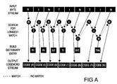
- Fig A is a simplified graphical depiction of the compression algorithm referred to above. This example shows an input data stream composed of the following characters: R I N T I N T I N. To follow the flow of the compression process, Fig A should be viewed from the top to the bottom, starting at the left and proceeding to the right. It is assumed that the dictionary has been reset and initialized to contain the eight reserved codewords and the first 256 entries of 0 to 255 including codewords for all the ASCII characters.
- the compression algorithm executes the following process with each byte in the data stream:
- the compression algorithm begins after the first R has been accepted by the compression engine.
- the input character R matches the character R that was placed in the dictionary during its initialization. Since there was a match, the DC engine accepts another byte, this one being the character I.
- the sequence RI is now searched for in the dictionary but no match is found. Consequently, a new dictionary entry RI is built and the codeword for the largest matching sequence (i.e., the codeword for the character R) is output.
- the engine now searches for I in the dictionary and finds a match just as it did with R.
- Another character is input (N) and a search begins for the sequence IN.
- the engine begins with a T from the previous sequence and then accepts the next character which is an I. It searches for the TI sequence and finds a match, so another byte is input. Now the chip is searching for the TIN sequence. No match is found, so a TIN entry is built and the codeword for TI is output.
- This sequence also exhibits the 1.778:1 compression ratio that the IN sequence exhibited.
- the net compression ratio for this string of 9 bytes is 1.143:1. This is not a particularly large compression ratio because the example consists of a very small number of bytes. With a larger sample of data, more sequences of data are stored and larger sequences of bytes are replaced by a single codeword. It is possible to achieve compression ratios that range from 1:1 up to 110:1.
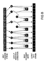
- FIG B A simplified diagram of the decompression process is shown in Fig B.
- This example uses the output of the previous compression example as input.
- the decompression process looks very similar to the compression process, but the algorithm for decompression is less complicated than that for compression, since it does not have to search for the presence of a given dictionary entry.
- the coupling of the two processes guarantees the existence of the appropriate dictionary entries during decompression.
- the algorithm simply uses the input codewords to look up the byte sequence in the dictionary and then builds new entries using the same rules that the compression algorithm uses. This is the only way that the decompression algorithm can recover the compressed data without a special dictionary sent with each data packet.
- the decompression engine begins by accepting the codeword for R. It uses this codeword to look up the byte value R. This value is placed on the last-in, first-out (LIFO) stack, waiting to be output from the chip. Since the R is one of the root codewords (one of the first 256 entries), the end of the list has been reached for this codeword. The output stack is then dumped from the chip. The engine then inputs the codeword for I and uses it to look up the byte value I. Again, this value is a root codeword, so the output sequence for this codeword is completed and the byte value for I is popped from the output stack.
- LIFO last-in, first-out
- a new dictionary entry is built using the last byte value that was pushed onto the output stack (I) and the previous codeword (the codeword for R). Each entry is built in this manner and contains a byte value and a pointer to the next byte in the sequence (the previous codeword). A linked list is generated in this manner for each dictionary entry.
- the next codeword is input (the codeword for N) and the process is repeated. This time an N is output and a new dictionary entry is built containing the byte value N and the codeword for I.
- the codeword for T is input, causing a T to be output and another dictionary entry to be built.
- the next codeword that is input represents the byte sequence IN.
- the decompression engine uses this codeword to reference the second dictionary entry, which was generated earlier in this example. This entry contains the byte value N, which is placed on the output stack, and the pointer to the codeword for I, which becomes the current codeword. This new codeword is used to find the next byte (I), which is placed on the output stack.
- the RESET codeword signifies the start of a new dictionary.
- the FLUSH codeword signifies that the DC chip has flushed out its buffer ie. it passes through the data currently held in the buffer without compressing that data prior to filling the buffer again with successive data and recommencing data compression.
- the DC chip inserts RESET and FLUSH codewords into the data stream in an algorithm-dependent manner.
- the tape format places constraints on when certain RESET and FLUSH codewords must occur and also ensures the writing to tape of certain information so as to enable the utilisation of certain ones of the RESET and FLUSH codewords in order to improve access to the compressed data.
- Decompression can only begin from a RESET codeword because the dictionary has to be rebuilt from the data. However, decompression can then stop at any subsequent FLUSH codeword even though this is not at the end of that particular dictionary. This is why it is advantageous to put FLUSH codewords at the end of each record so as to enable selective decompression of segments of data which are smaller than that used to build a dictionary.
- the supply of the data from a user (host computer) to a tape storage apparatus will generally be accompanied by ⁇ Jser separation of the data, whether this separation is the physical separation of the data into discrete packages (records) passed to the storage apparatus, or some higher level conceptual organisation of the records which is expressed to the storage apparatus by the host in terms of specific signals.
- This user-separation of data will have some particular significance to the host (though this significance will generally be unknown to the tape storage device). It is therefore appropriate to consider user separation as a logical segmentation even though its presence may be expressed to the storage apparatus through the physical separation of the incoming data.
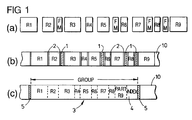
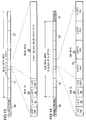
- Figure 1 (a) illustrates a sequence of user data and special separation signals that an existing type of host might supply to a tape storage apparatus.
- data is supplied in variable-length records R1 to R9; the logical significance of this physical separation is known to the host but not to the storage apparatus.
- user separation information is supplied in the form of special "file mark" signals FM.
- the file marks FM are provided to the storage apparatus between data records; again, the significance of this separation is unknown to the storage apparatus.
- the physical separation into records provides a first level of separation while the file marks provide a second level forming a hierarchy with the first level.
- Figure 1 (b) shows one possible physical organisation for storing the user data and user separation information of Figure 1 (a) on a tape 10, this organisation being in accordance with a known data storage method.
- the mapping between Figure 1 (a) and 1 (b) is straightforward - file marks FM are recorded as fixed-frequency bursts 1 but are otherwise treated as data records, with the records R1-R9 and the file marks FM being separated from each other by inter-block gaps 2 where no signal is recorded.
- the inter-block gaps 2 effectively serve as first-level separation marks enabling the separation of the stored data into the user-understood logical unit of a record; the file marks FM (fixed frequency burst 1) form second-level separation marks dividing the records into logical collections of records.
- Figure 1 (c) shows a second possible organisation which is known for storing the user data and user separation information of Figure 1 (a) on tape 10.
- the user data is organized into fixed-size groups 3 each including an index 4 for containing information about the contents of the group.
- the boundary between two groups 3 may be indicated by a fixed frequency burst 5.
- the division of data into groups is purely for the convenience of the storage apparatus concerned and should be transparent to the host.
- the user data within a group is not physically separated in any way and each record simply continues straight on from the end of the preceding one; all information regarding separation of the data in a group both into records and into the collection of records delimited by file marks is contained in the index of the group.
- records R1 to R8 and the first part of R9 are held in the illustrated group 3.
- the length of the index 4 will generally vary according to the number of separation marks present and the number of records in the group; however, by recording the index length in a predetermined location in the index with respect to the group ends, the boundary between the index and the last byte can be identified.
- a space with undefined contents, eg. padding, may exist between the end of the data area and the first byte of the index.
- the index 4 comprises two main data structures, namely a group information table 6 and a block access table 7.
- the number of entries in the block access table 7 is stored in a block access table entry (BAT ENTRY) count field in the group information table 6.
- the group information table 6 also contains various counts, such as a file mark count FMC (the number of file marks written since a beginning of recording (BOR) mark including any contained in the current group) and record counts RC (to be defined).
- the block access table 7 describes by way of a series of access entries, the contents of a group and, in particular, the logical segmentation of the user data held in the group (that is, it holds entries indicative of each record boundary and separator mark in the group).
- the access entries proceed in order of the contents of the group.
- the entries in the block access table each comprise a FLAG entry indicating the type of the entry and a COUNT entry indicating its value.
- the FLAG field is 8 bits and the COUNT field is 24 bits.
- the bits in the FLAG field have the following significance:
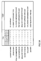
- FIG. 3 illustrates the seven types of entry which can be made in the block access table.
- the SEPARATOR MARK entry has the BOR and EOR bit set because it is defined as a record.
- the next four entries each have the XFR bit set because they represent information about data transfers.
- the START PART OF RECORD entry relates to a case where only the beginning of a record fits into the group and the next part of the record runs over to the following group.
- the only bit set in the MIDDLE PART OF RECORD entry flag is the data transfer bit because there will not be a beginning or end of a record in that group.
- the END PART OF RECORD entry does not have the EOR bit set in the FLAG - instead, the EOR bit is set in the TOTAL COUNT entry which gives the total record byte count.
- the last entry in the block access table for a group is always a SKIP entry which gives the amount of space in the group which is not taken up by user data ie. the entry in the Count field for the SKIP entry equals the group size (eg. 126632 bytes) minus the data area size.
- FIG. 4 An example of a block access table for the group 3 of records shown in Figure 1 (c) is shown in Figure 4.
- the count entries for records R1-8 are the full byte counts for those records whereas the count entry for record R9 is the byte count of the part of R9 which is in the group 3.
- the count entries for the file marks FM will be 0 or 1 according to the format.
- the count entry for the SKIP entry is 126632 minus the sum of the byte counts appearing previously in the table (not including Total Count entries).
- the block access table which signifies the algorithm used to compress the data in the group as shown in Figure 3A.
- the algorithm number which is entered in the COUNT field is preferably one which conforms to a standard for DC algorithm numbers.
- the data transfer and total count FLAG entries for compressed records in the group have the CMP bit set.
- compressed and uncompressed records in a group can be distinguished by a drive on the basis of the CMP bit.
- Figure 4A UBCX indicates an uncompressed byte count for record X and CBCX indicates a compressed byte count for record X.
- Fig 5 shows another possible organisation for storing user data and related information on tape.
- the user data is organised into fixed size groups each group including an index (which is uncompressed even if the group contains compressed data) comprising a block access table for containing information about the contents of the group.
- the boundaries between groups may be indicated by fixed frequency bursts.
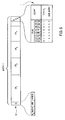
- this embodiment involves storing the information about the contents of the group in terms of "Entities", where an entity comprises one or more records.
- Entities where an entity comprises one or more records.
- an entity can contain n compressed records each having the same uncompressed length, where n is equal to or greater than 1.
- a group G comprises a single entity ENTITY 1 (or E1) which comprises four complete records CR1 - CR4 of compressed data and a header portion H of 8 bytes.
- the records CR1 - CR4 have the same uncompressed length but may well be of different length after undergoing data compression.
- the header portion H which remains uncompressed, in the datastream contains the following information:
- an entity may include trailer portions at the end of each of the records in the entity, the trailer portions containing the compressed byte count of each record.
- the trailer would occur immediately after an "end of record” (EOR) codeword.
- EOR end of record
- the length of the trailer e.g. 3 bytes, could also be indicated in the header portion, in the 12 bits reserved after the header length H L .
- each record in an entity has a trailer portion
- the trailer portion is inserted into the datastream, uncompressed, at the end of each compressed record.
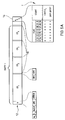
- the entity in Figure 5A comprises a header portion H and four compressed records CR1 - CR4 of equal length when uncompressed, each of which has an uncompressed trailer portion T.
- the trailer portion TR of each record contains the compressed byte count (CBC) of the record and a cyclic redundancy check (CRC).
- the trailer occupies 6 bits at the end of each record in this example.
- the length (T L ) of the trailer is included in the header portion H and occupies the last four bits of the first byte of the header portion H.
- trailer portions does not alter the nature of the entries in the block access table T although the SKIP count entry will accordingly be smaller.
- Insertion of compressed byte counts in the datastream has the advantage that a DC drive or a suitably configured non-DC drive can use these as pointers in a linked list to deduce where each compressed record begins and ends.
- An advantage of including the length of the header portion (and the trailer portion if appropriate) in the header is that it enables this length to be varied whilst still allowing a drive to skip over the header if desired.
- One possibility is to allow entities to contain only compressed records and this is preferred. This then means that the setting of the CMP bit in the FLAG field still indicates that the COUNT entry is a compressed byte count.
- another possibility is to allow entities to contain either compressed data or uncompressed data and to reserve a particular algorithm number eg. all zeros, to indicate that the data in an entity is uncompressed.
- an entity (E n ) may spread over more than one group eg. an entity E1 containing a single, relatively long record CR1 fills group G1 and runs over into group G2.
- the entries in the block access tables T1, T2 of the groups G1, G2 are also shown in Figure 6.
- a new entity is started as soon as possible in a group ie. at the start of the group or at the beginning of the first compressed record in the group if the previous record is uncompressed or at the beginning of the first new compressed record if the previous record is compressed and has run over from the previous group. Therefore, at the end of compressed record CR1, the next entity, E2 begins.
- Entity E2 contains four compressed records CR2 to CR5 of equal uncompressed length.
- groups may contain a mixture of entities containing compressed data and "naked records" containing uncompressed data.
- An example of this arrangement is shown in Figure 7 which also shows the corresponding entries in the block access table.
- a group G contains an entity comprising a header portion H and three compressed records CR1, CR2 and CR3.
- the group G also comprises an uncompressed record R4 (which has no header portion).
- the block access table T of the group G contains four entries:
- the CMP bit (the fourth bit of the FLAG field) is set for the entity byte count entry but not for the naked record byte count entry.
- a suitably configured non-DC drive can identify compressed and uncompressed data on a tape having a mixture of such data by checking whether the CMP bit is set in the relevant block access table entries.
- no separator marks are allowed within an entity. For example, if a host is sending a sequence of equal length records to a DC tape drive and there is a file mark or other separator mark within that sequence, then the first set of records before the separator mark will be placed in one entity, the separator mark will be written to tape and the set of records in the sequence which follow the file mark will be placed in a second entity. The corresponding entries for the two entities and the separator mark will of course be made in the block access table of the relevant group (assuming that only one group is involved in this example)
- Record Count - this field is a 4-byte field which specifies the sum of the values of the Number of Records in Current Group entry (see below) of the group information table of all groups up to and including the current group.
- this field is a 2-byte field which specifies the sum of the following:
- this field is a 2-byte field which specifies the running number of the highest-numbered previous group in which a separator mark, an access point or the beginning of an uncompressed record occurred. It shall contain all ZERO bits if no such previous group exists.
- the FLUSH codeword is also called the "end of record” (EOR) codeword so as to improve the access to compressed data.
- EOR end of record
- compression object The amount of compressed data which makes up a data dictionary is termed a "compression object".
- a compression object may encompass more than one group of data as illustrated in Figure 9. Where a record overlaps from one group to the next, a RESET codeword is placed in the data stream at the beginning of the very next compressed record.
- a Group G1 comprises three full compressed records CR1, CR2, CR3 and the first part of a fourth compressed record CR4.
- the last part of record CR4 extends into the next group G2.
- the records are not organised into entities in this example.
- the dictionary is reset (indicated by R in Figure 9) at the beginning of group G1.
- FLUSH codewords (indicated by F) are inserted into the datastream at the end of each record.
- the current dictionary continues until record CR4 ends at which time the dictionary is reset.
- the current compression object comprises records CR1 - CR4.
- record CR3 If it is later desired selectively to decompress, say, record CR3, this can be achieved by beginning decompression at the start of record CR1 ie. the start of the compression object containing record CR3, and decompressing data until the end of record CR3.
- a 'clean break' at the end of record CR3 can be achieved ie. without running over into the start of record CR4 due to the FLUSH codeword at the end of record CR3.
- providing FLUSH codewords which are accessible by the format interspersed between 'access points' enables selective decompression of segments of data which are smaller than the amount of data used to build a dictionary living data compression.
- the FLUSH codewords at the end of records are accessible since the compressed byte counts for each record are stored in the block access table.
- the start of a compression object which forms an 'access point' ie. a point at which the drive can start a decompression operation
- Access points may be explicitly noted in the block access table of each group.
- the presence of an access point may be implied by another entry in the block access table eg. the very presence of an algorithm number entry may imply an access point at the beginning of the first new record in that group.
- a bit in the algorithm number may be reserved to indicate that a new dictionary starts at the beginning of the first new record in that group.
- a compression object may encompass more than one entity as illustrated in Figure 10, so as to obtain the advantage of dictionary sharing over entities which contain relatively small amounts of data.
- Figure 10 shows three fixed size groups G1, G2, G3 of compressed data.
- Group G1 contains full record CR1 and the first part of the next record CR2.
- Record CR1 is the only record in entity E1.
- Group G2 contains the middle part of record CR2.
- Group G3 contains the end part of record CR2 and contains further records CR3 etc.
- Entity E2 contains a single, relatively long record CR2.
- the dictionary is reset (denoted by R) at the beginning of group G1 but, since record CR1 is relatively small, the compression object continues beyond record CR1 and entity E1 and includes record CR2 and entity E2.
- a compression object ends at the end of record CR2 and a new one begins at the beginning of record CR3.
- a further possibility is for the presence of a non-zero algorithm number in an entity header to indicate the start of a new dictionary and otherwise for the algorithm number header entry to take a predetermined value eg. zero.
- each record in an entity comprises a trailer (as mentioned previously with reference to Figure 5A) which contains the compressed byte count of the record and there are FLUSH codewords at the end of each record, the trailers can be used to advantage to achieve decompression on a per record basis.
- the DC chip inserts RESET codewords into the datastream in an algorithm-dependent manner - even in the middle of records.
- the above description relates to the RESET codewords which are forced, recognised and utilised by the tape format.
- the storage method and apparatus described hereinafter utilises a helical-scan technique for storing data in a format similar to that used for the storage of PCM audio data according to the DAT Conference Standard (March 1988, Electronic Industries Association of Japan, Tokyo, Japan).
- the present method and apparatus is, however, adapted for storing computer data rather than digitised audio information.
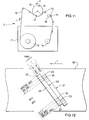
- Figure 11 shows the basic layout of a helical-scan tape deck 11 in which tape 10 from a tape cartridge 17 passes at a predetermined angle across a rotary head drum 12 with a wrap angle of 90°.
- the tape 10 is moved in the direction indicated by arrow T from a supply reel 13 to a take-up reel 14 by rotation of a capstan 15 against which the tape is pressed by a pinch roller 16; at the same time, the head drum is rotated in the sense indicated by arrow R.
- the head drum 12 houses two read/write heads HA, HB angularly spaced by 180°. In known manner, these heads HA, HB are arranged to write overlapping oblique tracks 20, 21 respectively across the tape 10 as shown in Figure 12.
- the track written by head HA has a positive azimuth while that written by head HB has a negative azimuth.
- Each pair of positive and negative azimuth tracks, 20, 21 constitutes a frame.
- each track comprises two marginal areas 22, two sub areas 23, two ATF (Automatic Track Following) areas 24, and a main area 25.
- the ATF areas 24 provide signals enabling the heads HA, HB to accurately follow the tracks in known manner.
- the main area 25 is used primarily to store the data provided to the apparatus (user data) although certain auxiliary information is also stored in this area; the sub areas 23 are primarily used to store further auxiliary information.
- the items of auxiliary information stored in the main and sub areas are known as sub codes and relate for example, to the logical organisation of the user data, its mapping onto the tape, certain recording parameters (such as format identity, tape parameters etc), and tape usage history.
- main area 25 and sub areas 23 are described in detail below.
- block size that are compatible with the aforementioned DAT Conference Standard.
- the data format of the main area 25 of a track is illustrated in Figure 13.
- the main area is composed of 130 blocks each thirty six bytes long.
- the first two blocks 26 are pre-ambles which contain timing data patterns to facilitate timing synchronisation on playback.
- the remaining 128 blocks 27 make up the 'Main Data Area'.
- Each block 27 of the Main Data Area comprises a four-byte 'Main ID' region 28 and a thirty-two byte 'Main Data' region 29, the compositions of which are shown in the lower part of Figure 13.
- the main ID region 28 is composed of a sync byte, two information-containing bytes W1, W2 and a parity byte.
- Byte W2 is used for storing information relating to the block as a whole (type and address) while byte W1 is used for storing sub codes.
- the Main Data region 29 of each block 27 is composed of thirty two bytes generally constituted by user-data and/or user-data parity. However, it is also possible to store sub codes in the Main Data region if desired.
- each sub area 23 of a track is illustrated in Figure 14.
- the sub area is composed of eleven blocks each thirty-six bytes long.
- the first two blocks 30 are pre-ambles while the last block 31 is a post-amble.
- the remaining eight blocks 32 make up the "Sub Data Area”.
- Each block 32 comprises a four-byte 'Sub ID' region 33 and a thirty-two byte 'Sub Data' region 34, the compositions of which are shown in the lower part of Figure 14.
- the Sub ID region 33 is composed of a sync byte, two information-containing bytes SW1, SW2 and a parity byte.
- Byte SW2 is used for storing information relating to the block as a whole (type and address) and the arrangement of the Sub Data region 34.
- Byte SW1 is used for storing sub codes.
- the Sub Data region 34 of each block 32 is composed of thirty two bytes arranged into four eight-byte "packs" 35. These packs 35 are used for storing sub codes with the types of sub code stored being indicated by a pack-type label that occupies the first half byte of each pack.
- the fourth pack 35 of every even block may be set to zero or is otherwise the same as the third pack while the fourth pack of every odd block is used to store parity check data for the first three packs both of that block and of the preceding block.
- user data is stored in the Main Data regions 29 of the Main Data Area blocks 27 of each track while sub codes can be stored both in the Sub ID and Sub Data regions 33, 34 of Sub Data Area blocks 32 and in the Main ID and Main Data regions 28, 29 of Main Data Area blocks 27.
- the sub codes of interest are an Area ID sub code used to identify the tape area to which particular tracks belong, and a number of sub codes used for storing counts of records and separator marks.
- the area ID sub code is a four-bit code stored in three locations. Firstly, it is stored in the third and fourth packs 35 of the Sub Data region 34 of every block in the Sub Data Areas of a track. Secondly, it is stored in byte SW1 of the Sub ID region 33 of every even Sub Data Area block 32 in a track, starting with the first block.
- the tape areas identified by this sub code will be described later on with reference to Figure 15.
- the sub codes used to store record and separator mark counts are stored in the first two packs 35 of the Sub Data region 34 of every block in the sub Data Areas of each track within the Data Area of the tape (see later with reference to Figure 15). These counts are cumulative counts which are the same as the counts in the group information table as previously described. These counts are used for fast searching the tape and to facilitate this process are constant over a set of frames constituting a group, the counts recorded in the tracks of a group of frames being the counts applicable as of the end of the group.
- the tape can be seen to be organised into three main areas, namely a lead-in area 36, a data area 37 and an end-of-data (EOD) area 38.
- the ends of the tape are referenced BOM (beginning of media) and EOM (end of media).
- User data is recorded in the frames of data area 37.
- the lead-in area 36 includes an area between a beginning-of-recording BOR mark and the data area 37 where system information is stored.
- the Area ID sub code enables the system area, data area 37 and EOD area 38 to be distinguished from one another.
- the frames 48 of the data area are arranged in groups 39 each of a fixed number of frames (for example, twenty two); optionally, these groups are separated from each other by one or more amble frames of predetermined content.
- these groups 39 correspond to the group 3 described with reference to Figure 1(c).
- the placement of user data into such groups 39 has no relation to the logical segmentation of the user data and information relating to this segmentation (record marks, separator marks) is stored in an index 40 that terminates the user-data in a group (the index actually occupies user data space within the group).
- index is shown in Figure 15 as occupying the final portion of the last frame of the group, this is only correct in relation to the arrangement of data prior to a byte-interleaving operation that is normally effected before data is recorded on tape; however, for present purposes, the interleaving operation can be disregarded.
- the information in the index is physically dispersed within the main data areas of the tracks in the group.
- the index 4 comprises two main data structures, namely a group information table and a block access table.
- the group information table is stored in a fixed location at the end of the group and is the same size independent of the contents of the group.
- the block access table varies in size depending on the contents of the group and extends from the group information table backwards into the remainder of the user data area of the frames of the group. Entries are made in the block access table from the group information table backwards to the boundary with real user data or 'pad'.
- FIG. 15 Also shown in Figure 15 are the contents of a sub data area block 32 of a track within a data-area group 39.
- the first two packs contain a separator mark count
- the second pack 35 also contains record counts RC (as defined above)
- the third pack 35 contains the Area ID and an absolute frame count AFC.
- the counts FMC, and RC held in the sub data area blocks are the same as those held in the group information table 41 of the group index 40.
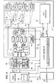
- FIG 16 is a block diagram of the storage apparatus for compressing and recording user data in accordance with the above-described tape format.
- the apparatus includes the tape deck 11 already described in part with reference to Figure 11.
- the apparatus includes an interface unit 50 for interfacing the apparatus with a host computer (not shown) via a bus 55; a group processor 51 comprising a data compression processor (DCP) and a frame data processor 52 for processing user-record data and separation data into and out of Main Data Area and Sub Data Area blocks 27 and 32; a signal organiser 53 for composing/decomposing the signals for writing/reading a track and for appropriately switching the two heads HA, HB; and a system controller 54 for controlling the operation of the apparatus in response to commands received from a computer via the interface unit 50.
- DCP data compression processor
- a frame data processor 52 for processing user-record data and separation data into and out of Main Data Area and Sub Data Area blocks 27 and 32
- a signal organiser 53 for composing/decomposing the signals for writing/reading a track and for appropriately
- DCP data compression processor
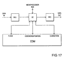
- the heart of the engine is a VLSI data compression chip (DC chip) which can perform both compression and decompression on the data presented to it. However, only one of the two processes (compression or decompression) can be performed at any one time.
- DC chip VLSI data compression chip
- Two first-in, first-out (FIFO) memories are located at the input and the output of the DC chip to smooth out the rate of data flow through the chip.
- the data rate through the chip is not constant, since some data patterns will take more clock cycles per byte to process than other patterns.
- the instantaneous data rate depends upon the current compression ratio and the frequency of dictionary entry collisions, both of which are dependent upon the current data and the entire sequence of data since the last dictionary RESET.
- the third section of the subsystem is a bank of static RAM forming an external dictionary memory (EDM) that is used for local storage of the current dictionary entries. These entries contain characters, codeword pointers, and control flags.
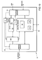
- Fig 18 shows a block diagram of the DC integrated circuit.
- the DC chip is divided into three blocks; the input/output converter (IOC), the compression and decompression converter (CDC), and the microprocessor interface (MPI).
- IOC input/output converter
- CDC compression and decompression converter
- MPI microprocessor interface
- the MPI section provides facilities for controlling and observing the DC chip. It contains six control registers, eight status registers, two 20 bit input and output byte counters, and a programmable automatic dictionary reset circuit.
- the control and status registers are accessed through a general-purpose 8 bit microprocessor interface bus.
- the control registers are used to enable and disable various chip features and to place the chip into different operating modes (compression, decompression, pass through, or monitor).
- the status registers access the 20 bit counters and various status flags within the chip.
- compression ratios can be improved by resetting the dictionary fairly frequently. This is especially true if the data stream being compressed contains very few similar byte strings. Frequent dictionary resets provide two important advantages. First, resetting the dictionary forces the codeword length to return to 9 bits. Second, new dictionary entries can be made that reflect the present stream of data (a form of adaption).
- the DC chip's interface section contains circuitry that dynamically monitors the compression ratio and automatically resets the dictionary when appropriate. Most data compression algorithms will expand their output if there is little or no redundancy in the data.
- the IOC section manages the process of converting between a byte stream and a stream of variable-length codewords (ranging from 9 bits to 12 bits). Two of the eight reserved codewords are used exclusively by the IOC. One of these codewords is used to tell the IOC that the length of the codewords must be incremented by one. Thus, the process of incrementing codeword size is decoupled from the CDC section - the IOC operates as an independent pipeline process, thus allowing the CDC to perform compression or decompression without being slowed down by the IOC.
- the second reserved codeword which is the FLUSH (or 'end of record' (EOR) ) codeword alerts the IOC that the next codeword is the last one associated with the current packet of data ie. the FLUSH codeword is actually the penultimate one of a compressed record. From this information, the IOC knows to finish its packing routine and end on a byte boundary. This feature allows compression of multiple input packets into one contiguous output packet while maintaining the ability to decompress this packet into its constituent packets. The IOC is also capable of allowing data to pass straight through from input to output without altering it, and of allowing data to pass through while monitoring the potential compression ratio of the data. These features can be used as another level of expansion protection.
- the CDC section is the engine that performs the transformation from uncompressed data to compressed data and vice versa. This section is composed of control, data path, and memory elements that are adjusted for maximum data throughput.
- the CDC interfaces with the IOC via two 12 bit buses. During compression, the IOC passes the input bytes to the CDC section, where they are transformed into codewords. These codewords are sent to the IOC where they are packed into bytes and sent out of the chip. Conversely, during decompression the IOC converts the input byte stream into a stream of codewords, then passes these codewords to the CDC section, where they are transformed into a stream of bytes and sent to the IOC.
- the CDC section also interfaces directly to the external RAM that is used to store the dictionary entries.
- the CDC makes use of two reserved codewords. The first is used any time a dictionary reset has taken place. The occurrence of this codeword causes two actions: the IOC returns to the state in which it packs or unpacks 9 bit codewords, and the CDC resets the current dictionary and starts to build a new one. Dictionary resets are requested by the MPI section via microprocessor control or the automatic reset circuitry.
- the second reserved codeword is generated during compression any time the CDC runs out of usable external RAM while trying to build a new dictionary entry. This event very rarely happens, given sufficient external RAM. However, as the amount of memory decreases, it is more likely that the CDC will encounter too many dictionary collisions and will not be able to build new dictionary entries.
- the data storage apparatus is arranged to respond to commands from a computer to load/unload a tape, to store a data record or separation mark, to enable compression of data, to search for selected separation marks or records, and to read back the next record.
- the interface unit 50 is arranged to receive the commands from the computer and to manage the transfer of data records and separation marks between the apparatus and computer. Upon receiving a command from the computer, the unit 50 passes it on to the system controller 54 which, in due course, will send a response back to the computer via the unit 50 indicating compliance or otherwise with the original command. Once the apparatus has been set up by the system controller 54 in response to a command from the computer to store or read data, then the interface unit 50 will also control the passage of records and separation marks between the computer and group processor 51.
- the group processor 51 is arranged to compress the user-data if required and to organise the user-data that is provided to it in the form of data records, into data packages each corresponding to a group of data.
- the processor 51 is also arranged to construct the index for each group and the corresponding sub codes.
- the group processor effects a reverse process enabling data records and separation marks to be recovered from a group read from tape prior to decompression.
- the form of the group processor 51 is shown in Figure 19.
- a buffer 56 which is arranged to hold more than one (for example, two) group's worth of data.
- the allocation of buffer space to incoming and outgoing data is controlled by a buffer space manager 57.
- the processor 51 communicates with the interface 50 via a first interface manager 58 and with the frame data processor 52 via a second interface manager 59.
- Overall control of the grouping process is effected by a grouping manager 60 which also generates the group indices and associated codes during recording (functional block 61) and interprets these indices and sub codes during reading (functional block 62).
- the grouping manager 60 is arranged to exchange coordination signals with the system controller 54.
- the DC processor DCP is operable to compress data for storage on tape or to decompress data to be read by a host. There are interconnections between the DC processor DCP and the interface manager 58, the buffer 56, the buffer space manager 57 and the grouping manager 60 for the interchange of control signals.
- the grouping manager 60 also comprises an entity manager (EM) which organises compressed data into entities and generates header portions for the entities.
- EM entity manager
- the grouping manager 60 and the buffer space manager 57 are control components and data for writing to tape does not pass through them, but rather passes directly from the buffer 56 to the interface manager 59.
- the interface 50 asks the buffer space manager 57 (via the interface manager 58) whether the processor 51 is ready to receive the record.
- the buffer space manager 57 may initially send a 'wait' reply but, in due course, enables the transfer of the data record from the host to the buffer 56.
- the DC processor DCP substitutes codewords for a proportion of the data in the record in accordance with a data compression algorithm as previously described.
- a host transfers records one at a time although multiple record transfers make sense for shorter records.
- the grouping manager 60 is connected to the buffer space manager 57 and tells the buffer space manager 57 how much more data the group can take before it runs into the index area of the group.
- the buffer space manager 57 notifies the grouping manager 60 whenever the maximum number of bytes has been transferred into the current group or the last byte from the host has been received.
- a transfer from the host cannot all fit inside a group, it is said to "span" the group boundary.
- the first part of the transfer goes into one group and the rest into subsequent groups.
- the buffer space manager 57 tells the grouping manager 60 if the host tries to supply more data than will fit in the current group being built. If no span occurs, the group index is updated and the grouping manager 60 waits for another write command. If a span occurs, the index of the current group is updated and that group is available for writing to tape. The next group is begun and the data from the host goes directly into the beginning of that new group.
- the record will be transferred to a buffer location that corresponds to the eventual positioning of the record data within the group of which it is to form a part.
- Information on the size of the record is passed to the grouping manager 60. When the host sends a separator indication this is also routed to the grouping manager 60.
- the grouping manager keeps track of the separator mark and record counts from BOR and uses this information in the construction of the index and separation-count and record count sub codes of a group.
- the index is constructed in a location in the buffer appropriate to its position at the end of a group.
- the entity manager EM In parallel, the entity manager EM generates an entity header portion for the current entity which will contain the compressed record data. The header portion is not compressed. The entity manager EM is responsible for ensuring that the rules governing entity formation are observed. These are:-
- Uncompressed records are organised directly into groups without forming part of an entity and information regarding the records is put into the group index. Uncompressed records do not have a header portion created for them.
- a group including its index and sub codes
- it is transferred to the frame data processor 52 for organisation into the blocks making up the main data areas and sub data areas of twenty two successive frames.
- Information about frame ID is in the datastream.
- the frame data processor 52 may be desirable to insert one or more amble frames between groups of frames recorded on the tape. This can be done by arranging for the frame data processor 52 to generate such amble frames either upon instruction from the group processor 51 or automatically at the end of a group if the processor 52 is aware of group structure.
- the general operation of the processor 51 can be kept as straight forward as possible with one group being read in and one group being processed and output.
- one group is being built with data from a host and one is being written to tape.
- the group processor 51 When data is being read from tape, the group processor 51 is arranged to receive user-data and sub-codes on a frame-by-frame basis from the frame data processor 52, the data being written into the buffer 56 in such a manner as to build up a group. The group processor 51 can then access the group index to recover information on the logical organisation (record/entity structure, separator marks) of the user-data in the group and an indication of whether the data is compressed.
- the group processor 51 can pass a requested record or separator mark to the host via the interface 50 in which case the data passes through the DC processor DCP unchanged.
- the entity header portions in compressed data are passed back to a host by a non-DC drive for use by the host.
- the data is compressed and is to be decompressed, the data is decompressed by the DC processor DCP in the manner described above before being passed to the host.
- the header portions from each entity are utilised by a DC drive but are not passed to the DC processor DCP.
- the algorithm number in the header portion is checked for consistency with the algorithm used by the DC processor DCP. Further, the number of compressed records in the entity is obtained from the header portion enabling a record count down to be performed as the entity data is passed to the DC processor DCP.
- each frame can be tagged with an in-group sequence number when the frame is written to tape.
- This in-group number can be provided as a sub code that, for example, is included at the head of the main data region of the first block in the Main Data Area of each track of a frame. The subcode is used on reading to determine where the related frame data is placed in the buffer 56 when passed to the group processor 51.
- the frame data processor 52 functionally comprises a Main-Data-Area (MDA) processor 65, a Sub-Data-Area (SDA) processor 66, and a sub code unit 67 ( in practice, these functional elements may be constituted by a single microprocessor running appropriate processes).
- MDA Main-Data-Area
- SDA Sub-Data-Area
- sub code unit 67 sub code unit
- the sub code unit 67 is arranged to provide subcodes to the processors 65 and 66 as required during writing and to receive and distribute sub codes from the processors 65, 66 during reading.
- sub codes may be generated/required by the group processor 51 or the system controller 54; the separation mark count sub codes are, for example, determined/used by the group processor 51 while the Area ID sub codes are determined/used by the controller 54.
- the sub codes may be permanently stored in the unit 67.
- any frame-dependent sub codes may conveniently be generated by the sub code unit 67 itself
- the MDA processor 65 is arranged to process a frame's worth of user data at a time together with any relevant sub codes.
- the processor 65 receives a frame's worth of user-data from the group processor 51 together with sub codes from the unit 67.
- the processor 65 interleaves the data, and calculates error correcting codes, before assembling the resultant data and sub codes to output the Main-Data-Area blocks for the two tracks making up a frame.
- scrambling (randomising) of the data may be effected to ensure a consistent RF envelope independent of the data contents of a track signal.
- the processor 65 effects a reverse process on the two sets of Main-Data-Area blocks associated with the same frame. Unscrambled, error-corrected and de-interleaved user data is passed to the group processor 51 and sub codes are separated off and distributed by the unit 67 to the processor 51 or system controller 54 as required.
- the operation of the SDA processor 66 is similar to the processor 65 except that it operates on the sub codes associated with the sub-data-areas of a track, composing and decomposing these sub codes into the from Sub-Data-Area blocks.
- the signal organiser 53 comprises a formatter/separator unit 70 which during recording (data writing) is arranged to assemble Main-Data-Area blocks and Sub-Data-Area blocks provided by the frame data processor 52 together with ATF signals from an ATF circuit 80, to form the signal to be recorded on each successive track.
- the necessary pre-amble and post-amble patterns are also inserted into the track signals where necessary by the unit 70.
- Timing signals for coordinating the operation of the unit 70 with rotation of the heads HA, HB are provided by a timing generator 71 fed with the output of a pulse generator 81 responsive to head drum rotation.
- the track signals output on line 72 from the unit 70 are passed alternately to head HA and head HB via a head switch 73, respective head drive amplifiers 74, and record/playback switches 75 set to their record positions.
- the head switch 73 is operated by appropriately timed signals from the timing generator 71.
- the track signals alternately generated by the heads HA and HB are fed via the record/playback switches 75 (now set in their playback positions), respective read amplifiers 76, a second head switch 77, and a clock recovery circuit 78 to the input of the formatter/separator unit 70.
- the operation of the head switch 77 is controlled in the same manner as that of the head switch 73.
- the unit 70 now serves to separate off the ATF signals and feed them to the circuit 80, and to pass the Main-Data-Area blocks and Sub-Data-Area blocks to the frame data processor 52. Clock signals are also passed to the processor 52 from the clock recovery circuit 78.
- the switches 75 are controlled by the system controller 54.
- the tape deck 11 comprises four servos, namely a capstan servo 82 for controlling the rotation of the capstan 15, first and second reel servos 83, 84 for controlling rotation of the reels 14, 15 respectively, and a drum servo 85 for controlling the rotation of the head drum 12.
- Each servo includes a motor M and a rotation detector D both coupled to the element controlled by the servo.
- Associated with the reel servos 83, 84 are means 86 for sensing the beginning-of-media (BOM) and end-of media (EOM); these means 86 may for example be based on motor current sensing, as the motor current of whichever reel is being driven to wind in tape (dependent on the direction of tape travel) will increase significantly upon stalling of the motor at BOM/EOM.
- the tape deck 11 further comprises the automatic track following circuit 80 for generating ATF signals for recordal on tape during recording of data.
- the ATF circuit 80 is responsive to the ATF track signal read from tape to provide an adjustment signal to the capstan servo 82 such that the heads HA, HB are properly aligned with the tracks recorded on the tape.
- the tape deck 11 also includes the pulse generator 81 for generating timing pulses synchronised to the rotation of the heads HA, HB.
- the operation of the tape deck 11 is controlled by a deck controller 87 which is connected to the servos 82 to 85 and to the BOM/EOM sensing means 86.
- the controller 87 is operable to cause the servos to advance the tape, (either at normal speed or at high speed) through any required distance. This control is effected either by energising the servos for a time interval appropriate to the tape speed set, or by feedback of tape displacement information from one or more of the rotation detectors D associated with the servos.
- the deck controller 87 is itself governed by control signals issued by the system controller 54.
- the deck controller 87 is arranged to output to the controller 54 signals indicative of BOM and EOM being reached.
- the system controller 54 serves both to manage high-level interaction between the computer and storage apparatus and to coordinate the functioning of the other units of the storage apparatus in carrying out the basic operations of Load/Write/Compress/Decompress/Search/Read/Unload requested by the computer. In this latter respect, the controller 54 serves to coordinate the operation of the deck 11 with the data processing portion of the apparatus.
- the system controller can request the deck controller 87 to move the tape at the normal read/write speed (Normal) or to move the tape forwards or backwards at high speed, that is Fast Forward (F.FWD) or Fast Rewind (F.RWD).
- the deck controller 87 is arranged to report arrival of BOM or EOM back to the system controller 54.
- the controller 54 Upon the host issuing a command to decompress a record, the controller 54 generates a search key having a value equal to the record count of the record to be decompressed.
- the current record count is held in the grouping manager 60 of the group processor 51.
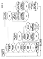
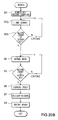
- the tape is advanced (or rewound as appropriate) at high speed (many times faster than normal) while the head drum is rotated at a speed to maintain the relative velocity of the heads HA, HB across the tape at a constant value; in this mode, it is possible to read the sub area of about one track in every three hundred (steps 91a and 91b). Reading track sub areas at speed is a known technique and will therefore not be described in detail.
- Fast forward searching is depicted in Figure 20A and fast backward searching is depicted in Figure 20B.
- the record count held in the second pack of each sub data area block is compared by the controller 54 with the search key (step 92a). If the record count is less than the search key, the search is continued; however, if the record count is equal to, or greater than the search key, fast forward searching is terminated and the tape is backspaced through a distance substantially equal to the distance between fast forward reads (step 93). This ensures that the record count held in the sub areas of the track now opposite the head drum will be less than the search key.
- the record count held in the second pack of each sub data block is compared by the controller 54 with the search key (step 92b). If the record count is more than the search key, the search is continued; however, if the record count is equal to or less than the search key, the fast rewind is stopped.
- the tape is advanced at its normal reading speed (step 94),and each successive group is read off tape in turn and temporarily stored in the buffer 56 of the group processor 51.
- the record count held in the index of each group is compared with the search key (step 95) until the count first equals or exceeds the search key. At this point, reading is stopped as the record searched for is present in the group in buffer 56 whose record count has just been tested. If entries are made in the block access table on a per record basis, the block access table of the index of this group is now examined to identify the record of interest ( step 96) and the address in the buffer of the first data record byte is calculated (step 97). Thereafter, the group processor 51 tells the system controller 54 that it has found the searched-for record and is ready to decompress and read the next data record; this is reported back to the host by the controller (step 98). The search operation is now terminated.
- the next step after the record of interest has been located is to check the algorithm number indicating which algorithm was used to compress the data in the record. This is done by examining the block access table of the relevant group if the algorithm number is stored in that table.
- the next step is to locate the beginning of the compression object containing the record of interest. This may be done in a variety of ways depending on the particular recording format.
- decompression commences from that point and continues until the FLUSH (or EOR) codeword at the end of the record is reached.
- the decompressed record can then be passed to the host.
- the presence of a FLUSH codeword at the end of the record means that the record can be decompressed cleanly without obtaining data from the beginning of the next record. If compressed records are organised into entities, the group of interest is located as described earlier with reference to Figures 20A and 20B.
- the relevant entity can then be located by using the #RECS entries in the entity headers within the group. Decompression is started from the nearest previous access point which may be found by checking the algorithm ID entry in the relevant entity and, if it indicates that the compressed data in that entity is a continuation of an earlier started dictionary, skipping back to the previous entity header and so on until an access point is found. Only decompressed data obtained from the relevant record or records is retained. The existence of data in the entity headers therefore has the advantage of facilitating finding relevant records and access points and allows the process of data management to be decoupled from that of decompression.
- these CBCs can be utilised to advantage in ascertaining when to start retaining decompressed data rather than (or as well as) counting FLUSH codewords during decompression.
- the presence of ancillary information in the data stream can be used to advantage in finding selected records, the nearest previous access point and in ascertaining the point at which decompressed data should be kept.
- the present invention is not limited to helical-scan data recording.
- the compression algorithm described is purely an example and the present invention may also be applicable to the storage of data which is compressed according to a different algorithm.
Landscapes
- Engineering & Computer Science (AREA)
- General Engineering & Computer Science (AREA)
- Signal Processing (AREA)
- Signal Processing For Digital Recording And Reproducing (AREA)
- Information Retrieval, Db Structures And Fs Structures Therefor (AREA)
Claims (13)
- Ein Datenspeicherungsverfahren zum Speichern von Benutzerdaten, die in einer Mehrzahl von Datensätzen (R) organisiert sind, und zugeordneten Informationen auf ein sequentiell-zugreifbares Datenspeicherungsmedium mit folgenden Schritten:Schreiben von Daten auf das Medium in Gruppen (G), die unabhängig von der Organisation der Datensätze (Rn) sind, wobei jede Gruppe (G) einen zugeordneten Index aufweist, undSchreiben von Informationen, die die Art und Größe jedes Datenobjekts, das in jeder Gruppe gespeichert ist, anzeigen, auf einen jeweiligen Eintrag in dem derselben zugeordneten Index,
dadurch gekennzeichnet, daß mindestens eine Gruppe eine Entität (E) enthält, wobei jede Entität eine Mehrzahl von Datensätzen (CRn) aufweist und einen jeweiligen Eintrag, der diesen Datensätzen gemeinsam ist und anzeigt, daß die Daten in denselben komprimiert sind (CMP), in dem Index aufweist, der dieser Gruppe zugeordnet ist, und wobei die Mehrzahl von Datensätzen (CRn) keinen anderen Eintrag, der sich auf dieselbe bezieht, in dem Index aufweist. - Das Verfahren gemäß Anspruch 1, bei dem jeder der Mehrzahl von Datensätzen (CRn) dieselbe Größe aufweist, wenn derselbe dekomprimiert ist.
- Das Verfahren gemäß Anspruch 1 oder 2, das ferner den Schritt des Schreibens von Entität-bezogenen Informationen, die Entität-Charakteristika anzeigen, aufweist, wobei die Informationen mindestens eine der folgenden Informationen aufweist:die Länge der Datensätze (CRn), die in der Entität (En) enthalten sind;die Anzahl von Datensätzen (CRn), die in der Entität (En) enthalten sind; undeine Angabe eines Algorithmus, der verwendet worden ist, um die Benutzerdaten zu komprimieren.
- Das Verfahren gemäß Anspruch 3, bei dem die Entität (En) ein Anfangsblockfeld (H), das derselben zugeordnet ist, auf dem Medium aufweist, und das ferner den Schritt des Schreibens der Entität-bezogenen Informationen auf das Anfangsblockfeld der Entität aufweist.
- Das Verfahren gemäß Anspruch 3 oder 4, bei dem eine spezielle Algorithmusangabe anzeigt, daß die Daten in einer Entität unkomprimiert sind.
- Das Verfahren gemäß Anspruch 3 oder Anspruch 4, das ferner den Schritt des Schreibens von Informationen aufweist, die die Länge der Entität-bezogenen Informationen anzeigen.
- Das Verfahren gemäß einem beliebigen der vorhergehenden Ansprüche, bei dem die Informationen, die den Inhalt der Gruppe (3) anzeigen, sowohl Informationen darüber sind, daß die Entität (En), die in dem Index angezeigt ist, komprimiert ist, als auch Informationen darüber, daß mindestens ein Datensatz (Rn), der von der Entität unabhängig und in dem Index angezeigt ist, nicht komprimiert ist.
- Das Verfahren gemäß Anspruch 7, bei dem die Entität (En) Datensätze (CRn) von komprimierten Benutzerdaten aufweist, wobei der Datensatz (Rn), der von der Entität unabhängig ist, unkomprimierte Benutzerdaten aufweist.
- Das Verfahren gemäß einem beliebigen der vorhergehenden Ansprüche, das ferner folgenden Schritt aufweist:
Starten einer neuen Entität (En) an dem Start des ersten Datensatzes (CRn), welcher in einer Gruppe (3) beginnt. - Das Verfahren gemäß Anspruch 9, bei dem die neue Entität (En) bei zumindest einem der folgenden Ereignisse erzeugt wird:a) Bilden einer neuen Gruppe (3),b) Änderung der unkomprimierten Größe der Datensätze, undc) Verändern eines Kompressionsalgorithmus, der verwendet worden ist, um die Benutzerdaten zu komprimieren.
- Das Verfahren gemäß einem beliebigen der vorhergehenden Ansprüche mit folgenden Schritten:Komprimieren der Benutzerdaten gemäß einem Kompressionsalgorithmus, der in der Lage ist, mindestens einige der Benutzerdaten in Codewörter zu komprimieren, indem er ein Wörterbuch verwendet, welches von den Daten abgeleitet ist; undBilden eines Wörterbuchs der Codewörter basierend auf den Benutzerdaten aus mehr als einem Datensatz.
- Eine Vorrichtung zum Speichern von Benutzerdaten, die in einer Mehrzahl von Datensätzen organisiert sind, auf einer Speichereinrichtung und zum Wiedergewinnen der Benutzerdaten von derselben, mit folgenden Merkmalen:einer ersten Einrichtung zum Schreiben der Daten auf ein sequentiell-zugreifbares Datenspeicherungsmedium in Gruppen (G), die von der Organisation der Datensätze (Rn) unabhängig sind, wobei jede Gruppe (G) einen zugeordneten Index aufweist; undeiner zweiten Einrichtung zum Schreiben von Informationen, die die Art und Größe jedes Datenobjekts anzeigen, das in jeder Gruppe gespeichert ist, in einen jeweiligen Eintrag in dem derselben zugeordneten Index,
dadurch gekennzeichnet, daß mindestens eine Gruppe eine Entität (E) enthält, wobei jede Entität eine Mehrzahl von Datensätzen (CRn) aufweist, und wobei die zweite Einrichtung angeordnet ist, um einen jeweiligen Eintrag, der diesen Datensätzen gemeinsam ist und anzeigt, daß die Daten in denselben komprimiert sind (CMP), in den Index zu schreiben, der dieser Gruppe zugeordnet ist, und keinen anderen Eintrag, der sich auf die Mehrzahl von Datensätzen (CRn) bezieht, in den Index zu schreiben. - Die Vorrichtung gemäß Anspruch 12 mit folgenden Merkmalen:einer Kompressionseinrichtung zum Komprimieren der Benutzerdaten gemäß einem Kompressionsalgorithmus, der in der Lage ist, mindestens einige der Benutzerdaten unter Verwendung eines Wörterbuchs, welches von den Daten abgeleitet ist, in Codewörter umzuwandeln; undeiner Wörterbucheinrichtung zum Bilden eines Wörterbuchs der Codewörter basierend auf den Benutzerdaten von mehr als einem Datensatz.
Applications Claiming Priority (3)
| Application Number | Priority Date | Filing Date | Title |
|---|---|---|---|
| GB909001335A GB9001335D0 (en) | 1990-01-19 | 1990-01-19 | Data storage on tape |
| GB9001335 | 1990-01-19 | ||
| PCT/GB1991/000083 WO1991011001A1 (en) | 1990-01-19 | 1991-01-18 | Data storage on tape |
Publications (2)
| Publication Number | Publication Date |
|---|---|
| EP0464190A1 EP0464190A1 (de) | 1992-01-08 |
| EP0464190B1 true EP0464190B1 (de) | 1996-03-06 |
Family
ID=10669627
Family Applications (1)
| Application Number | Title | Priority Date | Filing Date |
|---|---|---|---|
| EP91903655A Expired - Lifetime EP0464190B1 (de) | 1990-01-19 | 1991-01-18 | Datenspeicherung auf magnetband |
Country Status (6)
| Country | Link |
|---|---|
| US (1) | US5598388A (de) |
| EP (1) | EP0464190B1 (de) |
| JP (1) | JPH04505982A (de) |
| DE (1) | DE69117592T2 (de) |
| GB (1) | GB9001335D0 (de) |
| WO (1) | WO1991011001A1 (de) |
Families Citing this family (31)
| Publication number | Priority date | Publication date | Assignee | Title |
|---|---|---|---|---|
| US5426538A (en) * | 1992-03-13 | 1995-06-20 | Sony Corporation | Recording and/or reproducing apparatus with means for establishing an after-recording area |
| US5841600A (en) * | 1996-01-11 | 1998-11-24 | Quantum Corporation | Randomly ordered data block envelope tape format |
| US7657835B2 (en) * | 1997-01-31 | 2010-02-02 | Making Everlasting Memories, L.L.C. | Method and system for creating a commemorative presentation |
| US6340978B1 (en) * | 1997-01-31 | 2002-01-22 | Making Everlasting Memories, Ltd. | Method and apparatus for recording and presenting life stories |
| JPH10289537A (ja) * | 1997-04-11 | 1998-10-27 | Sony Corp | デジタルデータ記録方法およびデジタルデータ記録媒体 |
| EP0913762A1 (de) * | 1997-10-31 | 1999-05-06 | Hewlett-Packard Company | Datenkodierung |
| US6112261A (en) * | 1998-05-04 | 2000-08-29 | Hewlett-Packard Company | Data transferring system reading and temporarily storing a record until a length of the record is different from a defined record length parameter value |
| US6304914B1 (en) * | 1998-09-22 | 2001-10-16 | Microsoft Corporation | Method and apparatus for pre-compression packaging |
| US6624761B2 (en) | 1998-12-11 | 2003-09-23 | Realtime Data, Llc | Content independent data compression method and system |
| US6604158B1 (en) * | 1999-03-11 | 2003-08-05 | Realtime Data, Llc | System and methods for accelerated data storage and retrieval |
| US6601104B1 (en) | 1999-03-11 | 2003-07-29 | Realtime Data Llc | System and methods for accelerated data storage and retrieval |
| JP4340354B2 (ja) * | 1999-07-05 | 2009-10-07 | パイオニア株式会社 | ディジタルビットストリームのブロック化方法及び装置 |
| US20030191876A1 (en) * | 2000-02-03 | 2003-10-09 | Fallon James J. | Data storewidth accelerator |
| US20010047473A1 (en) * | 2000-02-03 | 2001-11-29 | Realtime Data, Llc | Systems and methods for computer initialization |
| US9143546B2 (en) * | 2000-10-03 | 2015-09-22 | Realtime Data Llc | System and method for data feed acceleration and encryption |
| US8692695B2 (en) * | 2000-10-03 | 2014-04-08 | Realtime Data, Llc | Methods for encoding and decoding data |
| DE10060295A1 (de) * | 2000-12-05 | 2002-06-27 | Bosch Gmbh Robert | Verfahren zum Abspeichern von akustischen Informationen und Verfahren zum Auswählen von einer nach diesem Verfahren abgespeicherten Information |
| US7386046B2 (en) | 2001-02-13 | 2008-06-10 | Realtime Data Llc | Bandwidth sensitive data compression and decompression |
| US7202872B2 (en) * | 2003-10-29 | 2007-04-10 | Via Technologies, Inc. | Apparatus for compressing data in a bit stream or bit pattern |
| US7039394B2 (en) * | 2003-11-25 | 2006-05-02 | Good Technology, Inc. | Communication system and method for compressing information sent by a communication device to a target portable communication device |
| WO2006020934A2 (en) * | 2004-08-13 | 2006-02-23 | Conexant Systems, Inc. | Systems and methods for decreasing latency in a digital transmission system |
| US20060218459A1 (en) * | 2004-08-13 | 2006-09-28 | David Hedberg | Coding systems and methods |
| GB2419026B (en) * | 2004-10-08 | 2009-05-06 | Hewlett Packard Development Co | Tape drive apparatus |
| US20080205635A1 (en) * | 2007-02-27 | 2008-08-28 | Glen Alan Jaquette | Apparatus, system, and method for self-describing heterogeneous magnetic tape formatting |
| JP4432088B2 (ja) * | 2007-02-28 | 2010-03-17 | インターナショナル・ビジネス・マシーンズ・コーポレーション | 一連の処理を所定の順序で行うための処理システム、ストレージ装置、及び方法 |
| WO2009112964A1 (en) * | 2008-03-12 | 2009-09-17 | Nxp B.V. | Method and apparatus for locating information on storage media |
| US20110161166A1 (en) * | 2009-12-30 | 2011-06-30 | Mindrum G Scott | System and method for capturing, processing, and presenting information |
| US20180039663A1 (en) * | 2016-08-03 | 2018-02-08 | Linkedin Corporation | Performing set operations on variable-length data sequentially stored and indexed to facilitate reverse reading |
| GB2565268B (en) * | 2017-06-22 | 2021-11-24 | Avago Tech Int Sales Pte Lid | Apparatus and method for packing a bit stream |
| US11393478B2 (en) | 2018-12-12 | 2022-07-19 | Sonos, Inc. | User specific context switching |
| US11635914B2 (en) | 2020-07-30 | 2023-04-25 | International Business Machines Corporation | Locating data within tape systems using sub dataset headers |
Family Cites Families (5)
| Publication number | Priority date | Publication date | Assignee | Title |
|---|---|---|---|---|
| US4703465A (en) * | 1985-12-04 | 1987-10-27 | 1K Entertainment Center Ltd. | Method and apparatus for producing an audio magnetic tape recording from a preselected music library |
| DE3702490A1 (de) * | 1987-01-28 | 1988-08-11 | Thomson Brandt Gmbh | Verfahren und vorrichtung zur digitalen nachrichtenuebertragung und/oder -aufzeichnung und -wiedergabe |
| US4872070A (en) * | 1987-09-11 | 1989-10-03 | Electro Sound, Inc. | System and method for high speed video tape reproduction |
| US4891784A (en) * | 1988-01-08 | 1990-01-02 | Hewlett-Packard Company | High capacity tape drive transparently writes and reads large packets of blocked data between interblock gaps |
| GB8800351D0 (en) * | 1988-01-08 | 1988-02-10 | Hewlett Packard Ltd | Data recorder |
-
1990
- 1990-01-19 GB GB909001335A patent/GB9001335D0/en active Pending
-
1991
- 1991-01-18 EP EP91903655A patent/EP0464190B1/de not_active Expired - Lifetime
- 1991-01-18 JP JP3503452A patent/JPH04505982A/ja active Pending
- 1991-01-18 DE DE69117592T patent/DE69117592T2/de not_active Expired - Fee Related
- 1991-01-18 WO PCT/GB1991/000083 patent/WO1991011001A1/en not_active Ceased
-
1994
- 1994-01-06 US US08/177,807 patent/US5598388A/en not_active Expired - Lifetime
Non-Patent Citations (2)
| Title |
|---|
| Hewlett-Packard Journal, June 1989, p.32-34 * |
| Mini-Micro Systems 1988, p.84-89 * |
Also Published As
| Publication number | Publication date |
|---|---|
| EP0464190A1 (de) | 1992-01-08 |
| GB9001335D0 (en) | 1990-03-21 |
| DE69117592D1 (de) | 1996-04-11 |
| WO1991011001A1 (en) | 1991-07-25 |
| JPH04505982A (ja) | 1992-10-15 |
| US5598388A (en) | 1997-01-28 |
| DE69117592T2 (de) | 1996-10-10 |
Similar Documents
| Publication | Publication Date | Title |
|---|---|---|
| EP0464190B1 (de) | Datenspeicherung auf magnetband | |
| US5280600A (en) | Storage of compressed data with algorithm | |
| US5298895A (en) | Data compression method and apparatus utilizing an adaptive dictionary | |
| EP0459041B1 (de) | Bandspeicherung | |
| EP0323890B1 (de) | Datenspeicherverfahren | |
| EP0760977B1 (de) | Anordnung von sätzen variabler länge in festen blöcken | |
| EP0871172A2 (de) | Verfahren und Medium zur Aufzeichnung digitaler Daten | |
| WO1991010998A1 (en) | Data storage | |
| EP0509642A2 (de) | Datenaufzeichnungs- und/oder Wiedergabegerät | |
| US5107505A (en) | Circuit of encoding and formatting data for rotating head recorders | |
| WO1991011000A1 (en) | Data dictionary sharing | |
| US4201980A (en) | GCR Data write control apparatus | |
| US6271979B1 (en) | Digital data recording and reproducing apparatus having record overflow determining means | |
| JPWO1997008696A1 (ja) | ディジタルデータ記録装置及び再生装置 | |
| EP0649138A1 (de) | Magnetisches aufzeichnungs-/wiedergabegerät | |
| EP0504779A2 (de) | Gerät zur Datenwiedergabe und/oder Datenaufzeichnung | |
| JPH04286755A (ja) | 磁気記録再生装置 | |
| JPH04286779A (ja) | 磁気記録再生装置 | |
| JPH04286780A (ja) | 磁気記録再生装置 | |
| JPH04286767A (ja) | 磁気記録再生装置 | |
| JPH04286778A (ja) | 磁気記録装置 |
Legal Events
| Date | Code | Title | Description |
|---|---|---|---|
| PUAI | Public reference made under article 153(3) epc to a published international application that has entered the european phase |
Free format text: ORIGINAL CODE: 0009012 |
|
| 17P | Request for examination filed |
Effective date: 19910906 |
|
| AK | Designated contracting states |
Kind code of ref document: A1 Designated state(s): DE FR GB IT NL |
|
| 17Q | First examination report despatched |
Effective date: 19940614 |
|
| GRAA | (expected) grant |
Free format text: ORIGINAL CODE: 0009210 |
|
| AK | Designated contracting states |
Kind code of ref document: B1 Designated state(s): DE FR GB IT NL |
|
| PG25 | Lapsed in a contracting state [announced via postgrant information from national office to epo] |
Ref country code: IT Free format text: LAPSE BECAUSE OF FAILURE TO SUBMIT A TRANSLATION OF THE DESCRIPTION OR TO PAY THE FEE WITHIN THE PRESCRIBED TIME-LIMIT;WARNING: LAPSES OF ITALIAN PATENTS WITH EFFECTIVE DATE BEFORE 2007 MAY HAVE OCCURRED AT ANY TIME BEFORE 2007. THE CORRECT EFFECTIVE DATE MAY BE DIFFERENT FROM THE ONE RECORDED. Effective date: 19960306 Ref country code: NL Free format text: LAPSE BECAUSE OF FAILURE TO SUBMIT A TRANSLATION OF THE DESCRIPTION OR TO PAY THE FEE WITHIN THE PRESCRIBED TIME-LIMIT Effective date: 19960306 |
|
| REF | Corresponds to: |
Ref document number: 69117592 Country of ref document: DE Date of ref document: 19960411 |
|
| ET | Fr: translation filed | ||
| NLV1 | Nl: lapsed or annulled due to failure to fulfill the requirements of art. 29p and 29m of the patents act | ||
| PLBE | No opposition filed within time limit |
Free format text: ORIGINAL CODE: 0009261 |
|
| STAA | Information on the status of an ep patent application or granted ep patent |
Free format text: STATUS: NO OPPOSITION FILED WITHIN TIME LIMIT |
|
| 26N | No opposition filed | ||
| REG | Reference to a national code |
Ref country code: GB Ref legal event code: IF02 |
|
| REG | Reference to a national code |
Ref country code: FR Ref legal event code: TP |
|
| PGFP | Annual fee paid to national office [announced via postgrant information from national office to epo] |
Ref country code: DE Payment date: 20050228 Year of fee payment: 15 |
|
| PG25 | Lapsed in a contracting state [announced via postgrant information from national office to epo] |
Ref country code: DE Free format text: LAPSE BECAUSE OF NON-PAYMENT OF DUE FEES Effective date: 20060801 |
|
| PGFP | Annual fee paid to national office [announced via postgrant information from national office to epo] |
Ref country code: FR Payment date: 20070207 Year of fee payment: 17 |
|
| REG | Reference to a national code |
Ref country code: FR Ref legal event code: ST Effective date: 20081029 |
|
| PG25 | Lapsed in a contracting state [announced via postgrant information from national office to epo] |
Ref country code: FR Free format text: LAPSE BECAUSE OF NON-PAYMENT OF DUE FEES Effective date: 20080131 |
|
| PGFP | Annual fee paid to national office [announced via postgrant information from national office to epo] |
Ref country code: GB Payment date: 20100125 Year of fee payment: 20 |
|
| REG | Reference to a national code |
Ref country code: GB Ref legal event code: PE20 Expiry date: 20110117 |
|
| PG25 | Lapsed in a contracting state [announced via postgrant information from national office to epo] |
Ref country code: GB Free format text: LAPSE BECAUSE OF EXPIRATION OF PROTECTION Effective date: 20110117 |