EP0464207A1 - Therapeutische vorrichtung mit laserstrahl - Google Patents
Therapeutische vorrichtung mit laserstrahl Download PDFInfo
- Publication number
- EP0464207A1 EP0464207A1 EP90905624A EP90905624A EP0464207A1 EP 0464207 A1 EP0464207 A1 EP 0464207A1 EP 90905624 A EP90905624 A EP 90905624A EP 90905624 A EP90905624 A EP 90905624A EP 0464207 A1 EP0464207 A1 EP 0464207A1
- Authority
- EP
- European Patent Office
- Prior art keywords
- laser light
- probe
- irradiation apparatus
- holder
- light penetrating
- Prior art date
- Legal status (The legal status is an assumption and is not a legal conclusion. Google has not performed a legal analysis and makes no representation as to the accuracy of the status listed.)
- Granted
Links
- 230000001225 therapeutic effect Effects 0.000 title abstract 2
- 239000000523 sample Substances 0.000 claims abstract description 209
- 230000000149 penetrating effect Effects 0.000 claims description 189
- 239000000463 material Substances 0.000 claims description 30
- 230000001681 protective effect Effects 0.000 claims description 23
- 238000002356 laser light scattering Methods 0.000 claims description 18
- 238000011282 treatment Methods 0.000 claims description 18
- 230000002093 peripheral effect Effects 0.000 claims description 7
- 230000035939 shock Effects 0.000 claims description 7
- 239000000919 ceramic Substances 0.000 claims description 6
- 239000012530 fluid Substances 0.000 claims description 3
- 238000009751 slip forming Methods 0.000 claims 1
- 230000005540 biological transmission Effects 0.000 abstract 2
- 238000000015 thermotherapy Methods 0.000 abstract 1
- 230000005068 transpiration Effects 0.000 abstract 1
- 210000004204 blood vessel Anatomy 0.000 description 33
- 239000002245 particle Substances 0.000 description 25
- 239000013307 optical fiber Substances 0.000 description 19
- 238000002266 amputation Methods 0.000 description 14
- 230000000740 bleeding effect Effects 0.000 description 14
- 206010028980 Neoplasm Diseases 0.000 description 13
- 230000003872 anastomosis Effects 0.000 description 12
- 238000000034 method Methods 0.000 description 11
- 230000023597 hemostasis Effects 0.000 description 8
- 238000002560 therapeutic procedure Methods 0.000 description 6
- 239000008280 blood Substances 0.000 description 5
- 210000004369 blood Anatomy 0.000 description 5
- 229910052782 aluminium Inorganic materials 0.000 description 4
- XAGFODPZIPBFFR-UHFFFAOYSA-N aluminium Chemical compound [Al] XAGFODPZIPBFFR-UHFFFAOYSA-N 0.000 description 4
- 230000015271 coagulation Effects 0.000 description 4
- 238000005345 coagulation Methods 0.000 description 4
- 239000006185 dispersion Substances 0.000 description 4
- 239000002612 dispersion medium Substances 0.000 description 4
- 238000009826 distribution Methods 0.000 description 4
- PCHJSUWPFVWCPO-UHFFFAOYSA-N gold Chemical compound [Au] PCHJSUWPFVWCPO-UHFFFAOYSA-N 0.000 description 4
- 229910052737 gold Inorganic materials 0.000 description 4
- 239000010931 gold Substances 0.000 description 4
- 229910052751 metal Inorganic materials 0.000 description 4
- 239000002184 metal Substances 0.000 description 4
- 239000002504 physiological saline solution Substances 0.000 description 4
- 239000010453 quartz Substances 0.000 description 4
- VYPSYNLAJGMNEJ-UHFFFAOYSA-N silicon dioxide Inorganic materials O=[Si]=O VYPSYNLAJGMNEJ-UHFFFAOYSA-N 0.000 description 4
- 230000008016 vaporization Effects 0.000 description 4
- 238000009834 vaporization Methods 0.000 description 4
- OKTJSMMVPCPJKN-UHFFFAOYSA-N Carbon Chemical compound [C] OKTJSMMVPCPJKN-UHFFFAOYSA-N 0.000 description 3
- 238000005452 bending Methods 0.000 description 3
- 239000011230 binding agent Substances 0.000 description 3
- 201000011510 cancer Diseases 0.000 description 3
- 230000006378 damage Effects 0.000 description 3
- 210000004185 liver Anatomy 0.000 description 3
- 230000008018 melting Effects 0.000 description 3
- 238000002844 melting Methods 0.000 description 3
- 229910052594 sapphire Inorganic materials 0.000 description 3
- 239000010980 sapphire Substances 0.000 description 3
- XKRFYHLGVUSROY-UHFFFAOYSA-N Argon Chemical compound [Ar] XKRFYHLGVUSROY-UHFFFAOYSA-N 0.000 description 2
- UQSXHKLRYXJYBZ-UHFFFAOYSA-N Iron oxide Chemical compound [Fe]=O UQSXHKLRYXJYBZ-UHFFFAOYSA-N 0.000 description 2
- 229910000831 Steel Inorganic materials 0.000 description 2
- 238000000149 argon plasma sintering Methods 0.000 description 2
- 229910052799 carbon Inorganic materials 0.000 description 2
- 238000010276 construction Methods 0.000 description 2
- 229910003460 diamond Inorganic materials 0.000 description 2
- 239000010432 diamond Substances 0.000 description 2
- 230000000694 effects Effects 0.000 description 2
- 239000011521 glass Substances 0.000 description 2
- 230000002008 hemorrhagic effect Effects 0.000 description 2
- NUJOXMJBOLGQSY-UHFFFAOYSA-N manganese dioxide Chemical compound O=[Mn]=O NUJOXMJBOLGQSY-UHFFFAOYSA-N 0.000 description 2
- 239000007769 metal material Substances 0.000 description 2
- RVTZCBVAJQQJTK-UHFFFAOYSA-N oxygen(2-);zirconium(4+) Chemical compound [O-2].[O-2].[Zr+4] RVTZCBVAJQQJTK-UHFFFAOYSA-N 0.000 description 2
- 238000007747 plating Methods 0.000 description 2
- 239000010959 steel Substances 0.000 description 2
- 239000000126 substance Substances 0.000 description 2
- 229920003002 synthetic resin Polymers 0.000 description 2
- 239000000057 synthetic resin Substances 0.000 description 2
- 210000001835 viscera Anatomy 0.000 description 2
- 229910001928 zirconium oxide Inorganic materials 0.000 description 2
- LFQSCWFLJHTTHZ-UHFFFAOYSA-N Ethanol Chemical compound CCO LFQSCWFLJHTTHZ-UHFFFAOYSA-N 0.000 description 1
- 229920002472 Starch Polymers 0.000 description 1
- 230000003213 activating effect Effects 0.000 description 1
- 239000000853 adhesive Substances 0.000 description 1
- 230000001070 adhesive effect Effects 0.000 description 1
- 230000000274 adsorptive effect Effects 0.000 description 1
- 229910052786 argon Inorganic materials 0.000 description 1
- 210000001367 artery Anatomy 0.000 description 1
- 239000012237 artificial material Substances 0.000 description 1
- 210000000013 bile duct Anatomy 0.000 description 1
- 238000007796 conventional method Methods 0.000 description 1
- 239000013078 crystal Substances 0.000 description 1
- 238000001704 evaporation Methods 0.000 description 1
- 230000008020 evaporation Effects 0.000 description 1
- 238000002474 experimental method Methods 0.000 description 1
- 229910002804 graphite Inorganic materials 0.000 description 1
- 239000010439 graphite Substances 0.000 description 1
- 230000012447 hatching Effects 0.000 description 1
- 239000011796 hollow space material Substances 0.000 description 1
- 230000001678 irradiating effect Effects 0.000 description 1
- WABPQHHGFIMREM-UHFFFAOYSA-N lead(0) Chemical compound [Pb] WABPQHHGFIMREM-UHFFFAOYSA-N 0.000 description 1
- 229910001234 light alloy Inorganic materials 0.000 description 1
- 239000007788 liquid Substances 0.000 description 1
- 238000004519 manufacturing process Methods 0.000 description 1
- 239000000155 melt Substances 0.000 description 1
- 239000002923 metal particle Substances 0.000 description 1
- 239000000203 mixture Substances 0.000 description 1
- 230000003287 optical effect Effects 0.000 description 1
- 210000003101 oviduct Anatomy 0.000 description 1
- 238000010422 painting Methods 0.000 description 1
- 238000005192 partition Methods 0.000 description 1
- 238000011084 recovery Methods 0.000 description 1
- 229920005989 resin Polymers 0.000 description 1
- 239000011347 resin Substances 0.000 description 1
- 238000007788 roughening Methods 0.000 description 1
- 230000009528 severe injury Effects 0.000 description 1
- 230000003595 spectral effect Effects 0.000 description 1
- 235000019698 starch Nutrition 0.000 description 1
- 239000008107 starch Substances 0.000 description 1
- 210000002784 stomach Anatomy 0.000 description 1
- 238000004381 surface treatment Methods 0.000 description 1
- BFKJFAAPBSQJPD-UHFFFAOYSA-N tetrafluoroethene Chemical group FC(F)=C(F)F BFKJFAAPBSQJPD-UHFFFAOYSA-N 0.000 description 1
- XLYOFNOQVPJJNP-UHFFFAOYSA-N water Substances O XLYOFNOQVPJJNP-UHFFFAOYSA-N 0.000 description 1
Images







Classifications
-
- A—HUMAN NECESSITIES
- A61—MEDICAL OR VETERINARY SCIENCE; HYGIENE
- A61B—DIAGNOSIS; SURGERY; IDENTIFICATION
- A61B18/00—Surgical instruments, devices or methods for transferring non-mechanical forms of energy to or from the body
- A61B18/18—Surgical instruments, devices or methods for transferring non-mechanical forms of energy to or from the body by applying electromagnetic radiation, e.g. microwaves
- A61B18/20—Surgical instruments, devices or methods for transferring non-mechanical forms of energy to or from the body by applying electromagnetic radiation, e.g. microwaves using laser
- A61B18/22—Surgical instruments, devices or methods for transferring non-mechanical forms of energy to or from the body by applying electromagnetic radiation, e.g. microwaves using laser the beam being directed along or through a flexible conduit, e.g. an optical fibre; Couplings or hand-pieces therefor
-
- A—HUMAN NECESSITIES
- A61—MEDICAL OR VETERINARY SCIENCE; HYGIENE
- A61B—DIAGNOSIS; SURGERY; IDENTIFICATION
- A61B18/00—Surgical instruments, devices or methods for transferring non-mechanical forms of energy to or from the body
-
- A—HUMAN NECESSITIES
- A61—MEDICAL OR VETERINARY SCIENCE; HYGIENE
- A61B—DIAGNOSIS; SURGERY; IDENTIFICATION
- A61B17/00—Surgical instruments, devices or methods
- A61B17/04—Surgical instruments, devices or methods for suturing wounds; Holders or packages for needles or suture materials
-
- A—HUMAN NECESSITIES
- A61—MEDICAL OR VETERINARY SCIENCE; HYGIENE
- A61B—DIAGNOSIS; SURGERY; IDENTIFICATION
- A61B18/00—Surgical instruments, devices or methods for transferring non-mechanical forms of energy to or from the body
- A61B2018/00964—Features of probes
-
- A—HUMAN NECESSITIES
- A61—MEDICAL OR VETERINARY SCIENCE; HYGIENE
- A61B—DIAGNOSIS; SURGERY; IDENTIFICATION
- A61B18/00—Surgical instruments, devices or methods for transferring non-mechanical forms of energy to or from the body
- A61B18/18—Surgical instruments, devices or methods for transferring non-mechanical forms of energy to or from the body by applying electromagnetic radiation, e.g. microwaves
- A61B18/20—Surgical instruments, devices or methods for transferring non-mechanical forms of energy to or from the body by applying electromagnetic radiation, e.g. microwaves using laser
- A61B18/22—Surgical instruments, devices or methods for transferring non-mechanical forms of energy to or from the body by applying electromagnetic radiation, e.g. microwaves using laser the beam being directed along or through a flexible conduit, e.g. an optical fibre; Couplings or hand-pieces therefor
- A61B2018/2255—Optical elements at the distal end of probe tips
- A61B2018/2261—Optical elements at the distal end of probe tips with scattering, diffusion or dispersion of light
Definitions
- This invention relates to laser light apparatus for medical treatments to permit amputations, incisions, vaporization of living tissues of an animal such as a human body, thermal therapy and the like, particularly to laser light apparatus for medical treatments with high abilities in amputations, hemostasis and anastomosis.
- the conventional method has been that the laser light is irradiated from the fore end of an optical fiber which is brought out of contact with the living tissues. But this method causes severe damage to the fore end portion of the optical fiber. Therefore, a method which has been utilized lately is as follows; First, laser light is transmitted into an optical fiber, whose fore end portion is located adjacent to treated living tissues. Next, the laser light fed out from the optical fiber is fed into an emitting probe, which is brought into or out of contact with the living tissues. Then, the laser light is emitted from the surface of the probe for irradiating against the living tissues. In this case, the probe should be brought into contact with the living tissues (hereafter "living tissue” is sometimes expressed by "tissue” only).
- the tissues When the tissues are incised with these contact probes, the tissues should be incised along an incision line repeatedly on the upper side surface of the tissues.
- a blood vessel having smaller diameter is amputated, bleeding is not caused so much, because, a target area of the blood vessel is coagulated by the laser light irradiation.
- the blood vessel should be often previously tied at the both sides of the target area with a medical thread.
- the probe In case of an incision of hemorrhagic tissues such as liver and the like with laser light irradiation, the probe must be repeatedly moved along an incision line little by little in order to suppress the bleeding caused at the target area as much as possible. Therefore, the medical operation requires much labour and must be done carefully.
- laser light should be irradiated many times.
- the laser light is often irradiated against also the normal tissues by mistake. Accordingly, the normal tissues are damaged.
- a ring-shaped high frequency snare is provided so as to encircle the tumor. Then, the tumor is amputated at its root with the snare.
- this treatment can not carried out with a high ability in hemostasis.
- electrical shock may be given to a patient.
- tissues around the tumor are often burned. As a result, the tissues are damaged.
- laser light irradiation apparatus consisting of a laser light generator, a laser light penetrating probe system and a laser light transmitting system.
- the laser light penetrating probe system is provided with an opposed pair of laser light penetrating probes.
- the opposed pair of penetrating probes can be controlled by a medical operator so that their opposed pair of laser light emitting portions are brought into or out of contact with each other.
- Laser light is impinged onto the pair of penetrating probes from the laser light generator through the laser light transmitting system. Then, a target area of tissues is pinched by the pair of penetrating probes so as to be disposed between the opposed pair of laser light emitting portions.
- the laser light can be irradiated against the target area of a blood vessel and the like from its both sides while the target area is pinched by the opposed pair of laser light penetrating probes which can be used like a pincette. Accordingly, abilities of this apparatus of the present invention in amputating and incising are progressed so as to be at least two times of the abilities of conventional apparatus. Additionally another surprising advantage can be obtained by this apparatus.
- a blood vessel having a diameter being larger than a certain length can not be amputated with single probe without bleeding. However, the blood vessel can be amputated easily with the opposed pair of laser light penetrating probes of the present invention.
- the both side walls in the longitudinal direction of the blood vessel are fused at the amputated portion of the blood vessel. Then, the side walls are connected each other so as to make two ends, which are opposed at the amputated portion. As a result, bleeding is prevented by the two ends and the tying of the blood vessel is not required.
- a laser light reflecting layer can be formed on each laser light penetrating probe at its side face being opposite to its other probe-side face.
- the laser light can be emitted from its other probe-side face concentratedly.
- Laser light scattering means can be provided on the laser light emitting portion of each laser light penetrating probe. In this case, the laser light can be irradiated efficiently against the target area of the tissues.
- a holder can be provided in this apparatus.
- This holder can hold the opposed pair of laser light penetrating probes and is operated by a medial operator so that its opposed pair of fore end portions are brought into or out of contact with each other.
- the opposed pair of penetrating probes can be operated like a pincette so as to be brought into or out of contact with each other corresponding to the movement of the pair of fore end portions of the holder.
- the laser light transmitting system such as an opposed pair of optical fibers can be set in the opposed pair of fore end portions of the holder respectively. Thus, damage to the laser light transmitting system can be prevented.
- the opposed pair of laser light penetrating probes are bent inwardly so that when their fore end portions are brought into contact with each other, a space is formed so as to be encircled by them. Then, the opposed pair of laser light emitting portions are formed on at least their base-side portions at the peripheral portion of the space adjacent to their contacting portion.
- Means for detecting a temperature of the target area of the tissues is preferably provided.
- the medical operation can be carried out under exact temperature control. Therefore, this means can be utilized efficiently for anastomosis of the tissues and thermal therapy for cancer tissues, because they particularly require the exact temperature control.
- a sensor detecting a temperature can be equipped to the opposed pair of laser light penetrating probes so as to be brought into contact with them. From a detected temperature obtained by this sensor, a temperature at a position other than the position where the sensor is inserted can be estimated. Because, there is a determined relation between the two temperatures. In the medical operation, the penetrating probes are brought into contact with the target area of the tissues and a temperature of the target area is required. Then, by this sensor, this required temperature can be estimated easily from the detected temperature.
- the laser light penetrating probe Since the laser light penetrating probe is normally fabricated from heat resistant ceramics, it is weak against a shock. Then, at least a portion of peripheral face of the penetrating probe can be covered with a protective material. This protective material has a strength being higher than the strength of the penetrating probe against the shock. Consequently, when the penetrating probe is received the shock, its damage can be reduced by the protective material.
- the laser light reflecting layer is formed easily on the internal peripheral face of the protective material such as the metal material.
- means for aspirating the target area of the tissues is preferably provided between the opposed pair of laser light penetrating probes.
- the target area of the tissues can be pulled up by aspirating. Therefore, the anastomosis, the amputations, the excisions and the thermal therapy for the target area can be performed precisely and easily.
- Means for detecting the temperature is preferably equipped to above mentioned means for aspirating, the temperature of the target area of the tissues can be detected directly during the aspirating.
- each emitting face is formed on the other probe-side face of each laser light penetrating probe and at least one portion of the emitting face is plane, the broad target area of the tissues can be pinched by the opposed pair of laser light penetrating probes.
- each laser light penetrating probe In case that just single impinging means is provided to each laser light penetrating probe, the laser light can not be transmitted to the penetrating probe efficiently. Therefore, plural number of laser light impinging means are preferably fixed to each laser light penetrating probe which is, for example, plane-shaped. Thus, the laser light can be transmitted to the inner side of the penetrating probes efficiently.
- Means for injecting a pressed fluid against the target area of the tissues can be provided between the opposed pair of laser light penetrating probes. During the medical operation, pieces of living tissues and blood are splashed to be attached to the penetrating probes. However, this situation can be eliminated by means for injecting.
- Apparatus of the present invention can be used not only in a surgical field but also in an internal medical field.
- the internal medical field preferable example is as follows;
- the holder is Y-shaped.
- the opposed pair of laser light penetrating probes are fixed to the both tip ends of the branch (V-shaped) portion of the holder respectively.
- the branch portion of the holder has flexibility.
- the holder is inserted in a sheath tube so that its tip ends and its base portion are projected upwards and downwards from the sheath tube to be exposed.
- the holder can be moved along the sheath tube corresponding to the pushing and pulling operation for its base portion.
- this apparatus can be utilized in medical operations for visceras such as a stomach and the like.
- an endoscope is inserted into a hole of a body.
- this apparatus is inserted along the hole.
- the opposed pair of penetrating probes which are put in the both divided portions respectively, are spread so as to be apart from each other.
- the laser light is irradiated against the target area, the holder is pulled so that the opposed pair of penetrating probes are closed each other.
- the target area of the tissues can be brought into contact with the opposed pair of penetrating probes from its both sides.
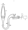
- Fig. 1 is a schematic illustration showing apparatus as a whole for a medical treatment related to the present invention
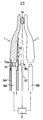
- Fig. 2 is a plan view, partly in cross section, of the laser light emitting portion of apparatus in Fig. 1
- Fig. 3 is an illustration showing laser light penetrating paths
- Fig. 4 is cross sectional view taken on line IV - IV of Fig. 3
- Fig. 5 is an illustration showing a power density distribution of laser light emission
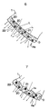
- Figs. 6 and 7 are schematic enlarged sectional views showing embodiments of scattering layers
- Figs. 8 to 10 are cross sectional views showing a process of an amputation for a blood vessel
- Figs. 11 to 13 are transverse cross sectional views of three kinds of laser light penetrating probes
- FIG. 14 to 16 are illustrations showing other embodiments of opposed pairs of laser light penetrating probes;
- FIG. 17 is a longitudinal cross sectional view showing an important part of still another opposed pair of laser light penetrating probes;
- Fig. 18 is an illustration showing an embodiment of excision of a projected tumor;
- Fig. 19 is a schematic illustration showing an important part of another opposed pair of laser light penetrating probes;
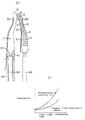
- Fig. 20 is an illustration showing an embodiment of sensors for detecting a temperature provided on an opposed pair of laser light penetrating probes;
- Fig. 21 is a graph showing a relation of the temperature of tissues at a position a sensor detecting the temperature is inserted and the temperature of the tissues at another position;
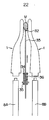
- Fig. 22 and 23 are illustrations showing other embodiments of sensors for detecting temperatures provided on opposed pairs of laser light penetrating probes;
- Fig. 24 is a longitudinal cross sectional view showing an opposed pair of laser light penetrating probes on which protective means formed of a protective material is provided;
- Figs. 25 to 27 are transverse cross sectional views showing other protective means formed of protective materials on the laser light penetrating probes;
- Figs. 28 and 29 are a perspective view and a longitudinal cross sectional view of means for aspirating provided on an opposed pair of laser light penetrating probes;
- Figs. 30 to 32 are perspective views of laser light penetrating probes having plane emitting surfaces;
- Fig. 33 is a transverse cross sectional view of an opposed pair of laser light penetrating probes being different each other;
- Figs. 34 and 35 are schematic illustrations of an opposed pair of laser light penetrating probes used in an internal medical treatment.
- Fig. 1 shows the whole of an embodiment of apparatus for a medical treatment related to the present invention.
- Laser light is emitted from a laser light generator 2 and transmitted through a laser light transmitting system explained after. Then, the laser light is impinged onto an opposed pair of laser light penetrating probes 1, 1.
- the laser light penetrating probes 1, 1 are disposed to be opposed each other. The laser light is emitted and irradiated against the target area of tissues.
- the laser light is progressed as follows;
- the laser light emitted from the laser light generator 2 goes through a lense 3 and impinged onto an optical fiber 4.
- the laser light is emitted from the fore end of the optical fiber 4 and goes through a lense 5.
- the laser light is divided into two portions by a 50 / 50 % spectral mirror 6.
- the divided portions of the laser light is impinged onto optical fibers 8A, 8B through lenses 7A, 7B respectively.
- the optical fibers 8A, 8B are covered with protective tubes respectively.
- the fore end portions of the optical fibers 8A, 8B are provided on, preferably so as to be included in, a U-shaped holder, in this embodiment a pinching holder 9.
- the pinching holder 9 is made of metal and moves like a pincette.
- the above mentioned opposed pair of penetrating probes 1, 1 are supported integrally by the fore end portions of the pinching holder 9.
- the opposed pair of penetrating probes 1, 1 are supported, for example, in a manner explained here.
- the penetrating probe 1 is supported by the pinching holder 9 and connected to the optical fiber 8A.
- a holder-cylinder 9A is connected to the penetrating probe 1 through a connector 10 so that the optical fiber 8A can be disposed so as to be apart from the base-side impinging surface of the penetrating probe 1.
- Fig. 2 only the left side of the holder 9 is shown.
- the right side laser light penetrating probe 1 is supported by the pinching holder 9 and connected to the optical fiber optically in the same way.
- the holder 9 is fabricated from a flexible material. Alternately, a resilient spring 11 is provided on the base portion of the holder 9 so that the fore end portions of the holder 9 can be moved freely so as to be closed and apart from each other corresponding to the operation of the medical operator.
- the laser light penetrating probe 1 is fabricated from a heat resistant ceramics such as quartz.
- a smaller radius side portion 1A is formed at the base side of the penetrating probe 1 which is engaged to the connector 10.
- a conical portion 1B is formed at the base portion so as to be slanting gently and continuous to the smaller radius side portion 1A.
- the smaller radius side portion 1A and the conical portion 1B are supported by the holder 9 coaxially with the optical fiber 8A. Then, the axis of the smaller radius side portion 1A and the conical portion 1B is substantially the same as the axis of impinged laser light.
- each laser light penetrating probe 1 is bent toward the fore end-side portion of another laser light penetrating probe 1 so as to be a bending portion 1C. Then, a parallel portion 1D is formed at the further fore end portion of the laser light penetrating probe 1 so as to be continuous to the bending portion 1C.
- the ridge line of the parallel portion 1D is parallel to the above mentioned axis of the base portion of the laser light penetrating probe 1.
- a laser light scattering layer D is formed at the internal side face of the parallel portion 1D.
- the scattering layer D is formed on another probe-side face which is opposed to the other laser light penetrating probe 1.
- this scattering layer D is directed by marking dots.
- a laser light reflecting layer R is formed at the surfaces of the above mentioned portions where the laser light is reflected.
- the reflecting layer R is directed by hatching.
- a gold plated layer or aluminum plated layer is coated on the surface of the laser light penetrating probe 1.
- the laser light scattering layer D can be formed by just roughening the surface of the laser light penetrating probe 1.
- the scattering layer D preferably contains scattering particles 20 and absorbing particles 21 of the laser light L and a binder 22, into which transmissible particles of laser light L are melted.
- the scattering layer D can be formed on a rough surface 1a of the laser light penetrating probe 1 to give a still larger scattering effect.
- the material of the laser light penetrating probe 1 related to the present invention is preferably ceramics such as artificial and natural diamond, sapphire, quartz and the like due to their high ability in heat resistance.
- the laser light scattering particles a material, which has a larger refractive index for the laser light than that of the laser light penetrating probe, is used.
- a material which has a larger refractive index for the laser light than that of the laser light penetrating probe.
- there are natural or artificial materials such as diamond, sapphire, quartz (it preferably has a high melting point), single crystal zirconium oxide (Zr2O3), glass having a high melting point, laser light transmissible synthetic resin having heat resistance and a laser light reflective metal such as gold, aluminum and the like.
- the material of the laser light scattering particles can be metal particles, which is laser light transmissible or not transmissible and whose surface is coated by the laser light reflective metal (gold, aluminum and the like) with a surface treatment such as plating and the like.
- the material forming the binder is preferably made from the laser light transmissible particle which can make a film when it melts and more preferably which has heat resistance such as natural or artificial, sapphire, quartz, glass, transmissible and heat resistant synthetic resin and the like.
- a suitable transmissible material is selected from these materials in consideration of the relation to the material of the laser light penetrating probe 1.
- the laser light absorbing particle is made of carbon, graphite, iron oxide, manganese dioxide and the any other materials which can absorb the laser light to generate heat energy.
- a content of each particle in the laser light scattering layer (wt%) and each average particle size is preferably within ranges as shown in a following table. More preferable content and particle size are put in parentheses.
- the thickness of the laser light scattering layer is preferably 10 ⁇ m - 5mm, more preferably 30 ⁇ m - 1mm.
- the scattering layer is formed as explained hereinafter. If the scattering layer having a desired thickness can not be formed by one cycle of the method, the method should be repeated until the layer having the desired thickness can be obtained.
- the above mentioned three kinds of particles are dispersed in a dispersion medium, then it is heated to a temperature which is higher than the melting point of the transmissible particle, then an uncoated probe is dipped in the heated dispersion.
- the three kinds of particles are melted to be sprayed to the uncoated probe.
- the dispersion dispersing the three kinds of particles can be painted to the uncoated probe.
- this painting method facilitates the operation, because what should be done in this method is that only a part, which is desired to be covered with the laser light scattering layer, of the uncoated probe is dipped in the dispersion and pulled up therefrom. Therefore, this method is practical and rational.
- suitable liquid such as water, alcohol or mixture of them can be used. Further sugar or starch is added to increase the viscosity of the dispersion medium.
- the laser light scattering layer D As described before, according to the present invention, by forming the laser light scattering layer D as well as laser light reflecting layer R, the laser light can be concentrated on the scattering layer D. Accordingly, as shown by power density distribution curves P, P in Figs. 4 and 5, the laser light can be irradiated concentratedly against the target area of the tissues from only the scattering layer D.
- the laser light L emitted from the laser light penetrating probe 1 passes through the laser light scattering layer D, the laser light L impinges on each laser light scattering particle 20 in the scattering layer D to be partially reflected on the surface of the scattering particle 20, or to be partially penetrated into and emitted from the particle 20 with refraction. Therefore, the laser light L is emitted in various directions from the whole external surface of the scattering layer D. This produces the large area of the laser light irradiation.
- the scattering layer D preferably contains the laser light absorbing particles 21 made of carbon and the like.
- the greater part of the energy of the laser light L is converted to heat energy He by means of the laser light absorbing particle 21, and the tissues are heated by the heat energy from the scattering layer D.
- the tissues can be incised with a low energy of the laser light L impinged onto the laser light penetrating probe 1. Therefore, when the tissues are incised, the laser light penetrating probe 1 can be moved quickly. Accordingly, the medical treatment can be carried out in short time. Further, since high power level of the laser light L is not required, the medical treatment can be carried out with a cheap and small scaled laser light generator.
- the producing method of the scattering layer if a dispersion containing the above mentioned laser light absorbing particles and the light scattering particles is coated on the surface of the laser light penetrating probe 1, after evaporation of a dispersion medium, the contact of the penetrating probe having the scattering layer with the tissues or other substances causes a damage to the scattering layer. Because, the both particles are attached to the surface of the laser light penetrating probe only by physical adsorptive power. Therefore, by the binder which sticks the laser light absorbing particles and the light scattering particles to the surface of the laser light penetrating probe, an adhesion of the scattering layer to the laser light penetrating probe is enhanced.
- Fig. 3 shows the paths of the laser light reflection in the laser light penetrating probe 1.
- the laser light is concentrated on the laser light scattering layer D, while the laser light is reflected in the penetrating probe 1.
- Fig. 3 shows that the penetrating probe 1 has a shape being suitable for the above laser light reflection.
- the scattering layer D is not necessary. However, if the scattering layer D is not provided, the graph of the laser light power density distribution of Fig. 4 will be projected toward the right sharply.
- the penetrating probe can be mainly used for only incisions with a lower ability in hemostasis, comparing the penetrating probe having the scattering layer D.
- the graph of the laser light power density distribution of Fig. 5 will be projected toward the right side of the upper portion sharply. This situation can be estimated from the angle of laser light emission shown in Fig. 3.
- the penetrating probe 1 can be used for the amputation of only thin blood vessel and the like.
- a laser light emitting portion, on which the laser light scattering layer D is formed, has a length of 2 - 10 mm, has preferably a length of 3 - 7 mm.
- Apparatus for the medical treatment related to the present invention is used by a medical operator in a way explained as follows; First, the power switch is put on. Next, as shown in Fig. 2, with the holder 9 controlled by the medical operator, the opposed pair of laser light penetrating probes 1, 1 are located so that the target area of the tissues are disposed between the opposed pair of penetrating probes 1, 1. In this embodiment, the opposed pair of penetrating probes 1, 1 are disposed at the both sides of the blood vessel BV respectively. Next, a switch 12 of Fig. 1 is put on. A hand switch (not shown) is provided on the holder 9 so as to be co-operated with the switch 12.
- the laser light is irradiated from the laser light scattering layers D, D against the blood vessel BV.
- a blood vessel BV has an original shape. Then, during the amputation with the laser light penetrating probes 1, 1, the walls of the blood vessel BV are melted by the laser light irradiation. As shown in Fig. 9, the walls of the blood vessel BV are fused between the laser light penetrating probes to form a connecting portion. Accordingly, blood can not flow at the connecting portion. Further, since the laser light is irradiated against the connecting portion, as shown in Fig. 10, the blood vessel is amputated. In this amputation, bleeding is prevented at the end portions of the both amputated blood vessels.
- the thick blood vessel can be amputated with the opposed pair of laser light penetrating probes without bleeding.
- the laser light is emitted from the opposed pair of laser light penetrating probes 1, 1, while heat is produced so as to melt the walls of the blood vessel BV.
- the blood vessel BV is pinched by the opposed pair of penetrating probes 1, 1.
- the walls are fused each other to produce the connecting portion which serves as a partition preventing the blood from flowing. Further, it can be thought that anastomosis is also performed during the amputation.
- the inventor confirms that arteries having diameters of about 6 mm can be amputated with the laser light penetrating probes of the present invention without bleeding by controlling the laser light emitting power.
- Apparatus for the medical treatment of the present invention can be used without bleeding in amputations and incisions of blood vessel, bile duct, a uterine tube and alimentary canal and in the incision of internal organs such as liver and the like. Additionally, it can be used in coagulation, the anastomosis, and vaporization. According to apparatus of the present invention, for a normal medical operation, the power level of the supplied laser light is smaller than 10 W. Further, attention should be paid that some medical operations can be carried out with a power level being smaller than 5 W.
- YAG laser light generally can be used as the laser light in the present invention. However, also other laser light such as argon laser light and the like can be used.
- the cross section of the laser light penetrating probe 1 is preferably a circle.
- the suitable cross section of the laser light penetrating probe 1 is an angular shape.
- the laser light emitting portion can be flat.
- the cross section of the laser light penetrating probe 1 is not limited to a certain shape.
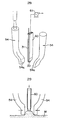
- Fig. 14 shows another laser light penetrating probe 50 which has another different shape and the paths of the laser light reflection. As clearly shown in Fig. 14, the laser light can reach at the laser light emitting portion with single reflection.
- Fig. 15 shows another laser light penetrating probe 51 which has still another shape and whose fore end portion is bent backward.
- the laser light can reach directly at the laser light emitting portion while there is substantially no laser light reflection.
- Fig. 16 shows a modified embodiment of the laser light penetrating probe.
- the conical portions of the opposed pair of penetrating probes are cut away so as to have the cross sections of Fig. 12. Also in this case, the laser light is not reflected so much.
- the laser light reflection layer R and the laser light scattering layer D are preferably formed, although they are not shown in these figures.
- the laser light reflection is the more in the laser light penetrating probe, the more laser light can reach at the laser light emitting portions. Therefore, by provision of the reflection layer R and the scattering layer D, high power level of laser light impinged into the probe is not required.
- an opposed pair of laser light penetrating probes 52, 52 provided with pair of constrictions 52A, 52A can be used effectively.
- the opposed pair of laser light scattering layers D, D are preferably formed on the inner surface of the opposed pair of constrictions 52A, 52A respectively.
- opposed pair of laser light penetrating probes 53, 53 are bent inwardly so that their fore end portions are brought into contact with each other (this condition is shown by imagine lines). Thus, a ring-shaped space encircled by them can be formed. Then, the laser light emitting portions are formed on at least the base-side portions of the opposed pair of penetrating probes 53, 53 at the peripheral portion of the ring-shaped space adjacent to their contacting portion respectively.
- the root of the projected tumor G can be excised easily by pulling the opposed pair of penetrating probes 53, 53 in the direction indicated by the arrow of this figure.
- Apparatus of the present invention can be utilized efficiently for not only the above mentioned amputation and incision but also for the anastomosis of the tissues, the thermal therapy for cancer tissues, the coagulation and the vaporization.
- means for detecting a temperature of the target area of the tissues is preferably provided.
- the temperature of the tissues should be controlled so as to be suitable one.
- the suitable temperature depends on kind of tissues. However, it can be determined generally in each treatment.
- the medical operation for the anastomosis can be carried out at the temperature of 60 to 80 o C.
- the thermal therapy can be carried out at the temperature of 42 to 45 o C.
- contact type such as a thermocouple or non-contact type such as optical means can be used.
- Fig. 20 shows the opposed pair of laser light penetrating probes 1, 1 having sensors 30, 30 detecting the temperature.
- Each sensor 30 consists of the thermocouple and is brought into contact with the back or inner surface of each penetrating probe 1.
- Each wires 31 connected to each sensor 30 can be supported by means of the holder 9A and the like.
- a detected temperature obtained by this sensor 30 is different from the temperature of the surface of the target area of the tissues such as cancer tissues M.
- the temperature of the position X of the tissues M being brought into contact with the laser light penetrating probe 1 and the detected temperature obtained by the sensor 30 has a determined relation. Therefore, according to this relation, by correcting the detected temperature obtained by the sensor 30, the temperature of the position X can be estimated. That is to say, the temperature of the tissues M also can be estimated.
- Fig. 22 shows the opposed pair of laser light penetrating probes 1, 1 having another sensor 32 detecting the temperature, which is brought into contact with the target are of the tissues such as the blood vessel BV directly. Accordingly, in this embodiment, the temperature of the target area can be detected directly.
- the sensor 32 is fixed to the fore end portion of a moving rod 33.
- a flange 34 is fixed at a suitable position of the rod 35.
- a spring seat 35 is fixed to the holder 9 so that the rod 35 can go through the spring seat 35 (the relational construction of the spring seat 35 and the holder 9 is not shown in this figure). Then, a resilient spring 36 is provided between the flange 34 and the spring seat 35.
- This sensor 32 is used to detect the temperature of the target area of the tissues M during the laser light irradiation.
- the tissues M are pinched by the opposed pair of laser light penetrating probes 1, 1.
- the moving rod 33 which has been pulled, is pushed toward the tissues M by means of the spring 36 so that the sensor 32 can be brought into contact with the tissues M.
- the laser light is irradiated against the tissues M by the opposed pair of penetrating probes 1, 1, while the temperature of the tissues M can be detected directly by the sensor 32.
- Fig. 23 shows a non-contact type of sensor detecting the temperature of the tissues M optically.
- laser light is irradiated against the tissues M from a optical fiber 37 through a lense system 38.
- the power level of the laser light emitted from the surface of the tissues M is detected.
- the temperature of the surface of the tissues M can be known.
- the power level of the laser light impinged onto the opposed pair of laser light penetrating probes 1, 1 from the laser light generator 2 can be controlled on the basis of a signal showing the detected temperature.
- apparatus of the present invention preferably has means for letting air, physiological saline solution and the like flow at the target area of the tissues M. By this means, the tissues can be cooled and the pieces of tissues and blood attached to the opposed pair of penetrating probes 1, 1 are washed away. The construction of this means is explained concretely here.
- a path of the air, physiological saline solution and the like is formed.
- This path consists of a gap formed between the holder-cylinder 9A and the optical fiber 8A, hollow space 10a formed at one side of the connector 10 and a notch 1a formed at the one corner of the penetrating probe 1.
- the air, physiological saline solution and the like are supplied and flown through the path so as to be injected against the target area of the tissues M.
- the laser light penetrating probe 1 is fabricated from ceramics.
- the strength of the penetrating probe 1 depends on the kind of its material. However, in many cases, the penetrating probe is often broken by a shock caused by being brought into contact with other substances. Therefore, at least one portion of the peripheral surface of the laser light penetrating probe 1 is preferably covered with a protective material having high strength against the above mentioned shock.
- each protective material 40 is engaged to each connector 10.
- the engaged face of the material 40 can be fixed to the connector 10 with adhesive and the like.
- each protective material 40 On the inner surface of each protective material 40, a laser light reflecting layer (not shown) such as a plating layer of gold can be formed. Therefore, the laser light impinged onto the laser light penetrating probe 1 can reach at the laser light emitting portion of the penetrating probe 1, while the laser light continues to reflect at the reflecting layer.
- the reflecting layer can be formed on the inner surface of the protective material 40 more easily, comparing that the laser light reflecting layer is formed on the surface of the penetrating probe 1 directly from the point of view of manufacturing.
- the protective material is fabricated from steel, rustless steel, light alloy containing aluminum and the like, other metal materials, resin of tetrafluorethylene and the like. Then, the protective material is formed to be a predetermined shape so as to be fit on the surface of the laser light penetrating probe. Alternately, ceramics having a high strength can be coated on the surface of the penetrating probe.
- the shape of the protective material can be determined corresponding to the shape of the laser light penetrating probe.
- a protective material 40 can be formed so as to fit on the surface of the laser light penetrating probe 1 having an egg-shaped cross section.
- an original protective cylinder 40a shown by dashed line is provided so as to be coaxial with the laser light penetrating probe 1. Then, the both upper and lower portions of the cylinder 40a of this figure and the emitting portion-side portion are cut off to form a protective material 40 in order to protect the penetrating probe 1.
- means 60 for aspirating the target area of the tissues is preferably provided between the opposed pair of laser light penetrating probes 54, 54.
- at least the laser light emitting portions 54a, 54a of the opposed pair of penetrating probes 54, 54 are preferably flat.
- means 60 for aspirating is formed by a cylinder having an opening at its upper end. Then, means 60 is connected to a suction pump 61. By activating the suction pump 61, the target area can be pulled up.
- the laser light is irradiated from the flat emitting portions 54a, 54a of the opposed pair of penetrating probes 54, 54 against the target area.
- the temperature of the tissues is preferably adjusted so as to be about 60 o C - 80 o C. Therefore, the sensor 30 for detecting temperature and the lead wire 31 are preferably provided along the means 60 for aspirating.
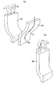
- the laser light emitting portion is preferably flat. Therefore, as shown in Fig. 30, in order to form the flat emitting portions easily, opposed pair of laser light penetrating probes 55, 55 can be formed so as to be curved plates. However, in this embodiment, as long as single optical fiber 8 is used, the laser light can not be irradiated uniformly with respect to the vertical direction to the longitudinal direction of the laser light penetrating probe 55. Accordingly, as shown in Fig. 30, plural number of (in this embodiment, three) optical fibers 8, 8 are preferably provided. Additionally, the scattering layer, which is indicated by marking dots in this figure, can be formed on each emitting portion.
- the laser light penetrating probe 56 can be formed as follows; Its inner surface is curved plate-shaped. On the other hand, its back surface other than the fore end portion being opposite to the emitting portion is a portion of the side face of a cylinder. Also in this case, plural number of optical fibers 8, 8 can be provided.
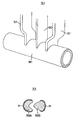
- Fig. 33 shows an opposed pair of laser light penetrating probes 58A, 58B having different shapes respectively. Further, an opposed pair of laser light penetrating probes (not shown) can be formed so as to cross each other like a pair of scissors.
- apparatus of the present invention are used in a surgical field.
- apparatus can be used also in an internal medical field.
- a holder 90 is Y-shaped.
- the opposed pair of laser light penetrating probes 1, 1 are fixed to the both tip ends of the branch (V-shaped) portion of the holder respectively through the connectors shown in Fig. 2.
- the branch portion has flexibility.
- the holder 90 is inserted in a sheath tube 91 so that its tip ends and its base portion are projected upwards and downwards from the sheath tube 91 to be exposed.
- the holder 90 can be moved along the sheath tubes 91 corresponding to the pushing and pulling operations for the base portion of the holder. Therefore, as shown in Fig. 34, when the holder 90 is pushed, its branch portion is spread so that both divided portions consisting of the branch portion are apart from each other. On the other hand, as shown in Fig. 35, when the holder 90 is pulled, its branch is closed. That is to say, situation of the apart laser light penetrating probes 1, 1 and the situation of the closing laser light penetrating probes 1, 1 can be changed each other corresponding to the pushing and pulling operation for the base portion of the holder 90. Generally, first, an endoscope is inserted into a hole of a body. Next, this apparatus is inserted along the hole.
- the opposed pair of penetrating probes 1, 1, which are put in the both divided portions respectively, are spread so as to be apart from each other. Further, when the laser light is irradiated against the target area, the holder 90 is pulled so that the opposed pair of penetrating probes 1, 1 are closed each other. Thus, the target area of the tissues can be brought into contact with the opposed pair of penetrating probes 1, 1 from its both sides. These operations are performed while the movement of apparatus in the body can be observed by the endoscope. Alternately, by forming a through-hole other than the hole for observation, instead of the sheath tube 91, the holder 90 can be inserted through the through-hole.
- laser light irradiation apparatus for medical treatment, which can amputate and incise the target area of the tissues with single operation with the high ability in hemostasis.
- apparatus of the present invention laser light is not irradiated against other normal tissues.
- this apparatus can amputate the blood vessel without tying of the blood vessel at the both sides of the target area. Accordingly, due to this laser light irradiation apparatus, medical operations can be finished in short time. As a result, this apparatus can be utilized widely in the medical operations and treatments of the surgical field and the internal medical field.
Landscapes
- Health & Medical Sciences (AREA)
- Life Sciences & Earth Sciences (AREA)
- Surgery (AREA)
- Physics & Mathematics (AREA)
- Medical Informatics (AREA)
- General Health & Medical Sciences (AREA)
- Biomedical Technology (AREA)
- Heart & Thoracic Surgery (AREA)
- Otolaryngology (AREA)
- Molecular Biology (AREA)
- Animal Behavior & Ethology (AREA)
- Engineering & Computer Science (AREA)
- Public Health (AREA)
- Veterinary Medicine (AREA)
- Nuclear Medicine, Radiotherapy & Molecular Imaging (AREA)
- Optics & Photonics (AREA)
- Electromagnetism (AREA)
- Laser Surgery Devices (AREA)
- Radiation-Therapy Devices (AREA)
Applications Claiming Priority (3)
| Application Number | Priority Date | Filing Date | Title |
|---|---|---|---|
| JP01234790A JP3148216B2 (ja) | 1990-01-22 | 1990-01-22 | レーザ光照射による治療装置 |
| JP12347/90 | 1990-01-22 | ||
| PCT/JP1990/000447 WO1991010404A1 (fr) | 1990-01-22 | 1990-03-31 | Appareil therapeutique utilisant un faisceau laser |
Publications (3)
| Publication Number | Publication Date |
|---|---|
| EP0464207A1 true EP0464207A1 (de) | 1992-01-08 |
| EP0464207A4 EP0464207A4 (en) | 1992-06-03 |
| EP0464207B1 EP0464207B1 (de) | 1996-02-14 |
Family
ID=11802751
Family Applications (1)
| Application Number | Title | Priority Date | Filing Date |
|---|---|---|---|
| EP90905624A Expired - Lifetime EP0464207B1 (de) | 1990-01-22 | 1990-03-31 | Therapeutische vorrichtung mit laserstrahl |
Country Status (10)
| Country | Link |
|---|---|
| US (2) | US5328488A (de) |
| EP (1) | EP0464207B1 (de) |
| JP (1) | JP3148216B2 (de) |
| KR (1) | KR960010983B1 (de) |
| CN (1) | CN1053540A (de) |
| AU (1) | AU644069B2 (de) |
| CA (1) | CA2049013C (de) |
| DE (1) | DE69025402T2 (de) |
| WO (1) | WO1991010404A1 (de) |
| ZA (1) | ZA91287B (de) |
Cited By (2)
| Publication number | Priority date | Publication date | Assignee | Title |
|---|---|---|---|---|
| WO1995031242A1 (de) * | 1994-05-11 | 1995-11-23 | Arzneimittel Gmbh Apotheker Vetter & Co. Ravensburg | Verfahren zur schaffung eines venenzugangs sowie vorrichtung zur durchführung des verfahrens |
| WO1998043704A1 (en) * | 1997-04-02 | 1998-10-08 | Wound Healing Of Oklahoma, Inc. | Laser light delivery system and method |
Families Citing this family (52)
| Publication number | Priority date | Publication date | Assignee | Title |
|---|---|---|---|---|
| US5300065A (en) * | 1992-11-06 | 1994-04-05 | Proclosure Inc. | Method and apparatus for simultaneously holding and sealing tissue |
| WO1995013747A1 (en) * | 1992-11-06 | 1995-05-26 | Premier Laser Systems, Inc. | Apparatus for simultaneously holding and sealing tissue |
| US5416878A (en) * | 1993-07-29 | 1995-05-16 | Endeavor Surgical Products, Inc. | Surgical methods and apparatus using a bent-tip side-firing laser fiber |
| AU6786796A (en) * | 1995-07-24 | 1997-02-18 | Vibeke Elisabeth Hjortdal | Transilluminator for use in human and veterinary medicine |
| US7473251B2 (en) | 1996-01-05 | 2009-01-06 | Thermage, Inc. | Methods for creating tissue effect utilizing electromagnetic energy and a reverse thermal gradient |
| US20030212393A1 (en) | 1996-01-05 | 2003-11-13 | Knowlton Edward W. | Handpiece with RF electrode and non-volatile memory |
| US7452358B2 (en) | 1996-01-05 | 2008-11-18 | Thermage, Inc. | RF electrode assembly for handpiece |
| US7229436B2 (en) | 1996-01-05 | 2007-06-12 | Thermage, Inc. | Method and kit for treatment of tissue |
| US5760395A (en) * | 1996-04-18 | 1998-06-02 | Universities Research Assoc., Inc. | Method and apparatus for laser-controlled proton beam radiology |
| US6221069B1 (en) | 1996-11-26 | 2001-04-24 | S.L.T. Japan Co., Ltd. | Apparatus for medical treatment |
| US6039729A (en) * | 1997-08-08 | 2000-03-21 | Cynosure, Inc. | Portable cautery system |
| EP0919196A3 (de) | 1997-11-25 | 2000-04-26 | S.L.T. Japan Co., Ltd. | Gerät für medizinische Behandlungen |
| US6256530B1 (en) | 1998-09-15 | 2001-07-03 | Denvu, L.L.C. | Optical instrument and technique for cancer diagnosis using in-vivo fluorescence emission of test tissue |
| US6577884B1 (en) | 2000-06-19 | 2003-06-10 | The General Hospital Corporation | Detection of stroke events using diffuse optical tomagraphy |
| AU2003245573A1 (en) | 2002-06-19 | 2004-01-06 | Palomar Medical Technologies, Inc. | Method and apparatus for treatment of cutaneous and subcutaneous conditions |
| US7856985B2 (en) | 2005-04-22 | 2010-12-28 | Cynosure, Inc. | Method of treatment body tissue using a non-uniform laser beam |
| WO2007129424A1 (ja) * | 2006-04-14 | 2007-11-15 | Sumitomo Electric Industries, Ltd. | 治療装置及び治療方法 |
| US20070255356A1 (en) * | 2006-04-28 | 2007-11-01 | Ondine International, Ltd. | Photodisinfection delivery devices and methods |
| US7586957B2 (en) | 2006-08-02 | 2009-09-08 | Cynosure, Inc | Picosecond laser apparatus and methods for its operation and use |
| US8272868B2 (en) * | 2006-09-13 | 2012-09-25 | Clark David J | Dental curing lights and a seamless, single load cavity preparation and filling technique |
| JP5222095B2 (ja) * | 2008-10-30 | 2013-06-26 | 株式会社長田中央研究所 | レーザプローブ |
| US8685010B2 (en) * | 2008-11-24 | 2014-04-01 | Gradiant Research, Llc | Photothermal treatment of soft tissues |
| US20110190749A1 (en) | 2008-11-24 | 2011-08-04 | Mcmillan Kathleen | Low Profile Apparatus and Method for Phototherapy |
| RU2392018C1 (ru) * | 2008-11-26 | 2010-06-20 | Федеральное государственное унитарное предприятие "Федеральный научно-производственный центр "Прибор" | Лазерное медицинское устройство |
| CN102596126B (zh) * | 2009-07-29 | 2014-08-13 | 爱尔康蓝斯克斯股份有限公司 | 用于眼科手术激光的光学系统 |
| RU2429890C1 (ru) * | 2010-01-26 | 2011-09-27 | Общество с ограниченной ответственностью "Научно-производственное предприятие Волоконно-Оптического и Лазерного Оборудования" (ООО "НПП ВОЛО") | Способ управления температурой поверхностного слоя кожи и подкожных слоев биоткани |
| IT1405000B1 (it) * | 2010-02-04 | 2013-12-16 | El En Spa | Dispositivo per il trattamento del canale vaginale e relativo apparecchio |
| EP2624777B1 (de) | 2010-10-07 | 2019-03-20 | Gradiant Research, Llc | Vorrichtung für eine hautkrebs-wärmetherapie |
| US9456870B2 (en) | 2011-05-16 | 2016-10-04 | Covidien Lp | Optical energy-based methods and apparatus for tissue sealing |
| US10117705B2 (en) | 2011-05-16 | 2018-11-06 | Covidien Lp | Optical recognition of tissue and vessels |
| US9113934B2 (en) | 2011-05-16 | 2015-08-25 | Covidien Lp | Optical energy-based methods and apparatus for tissue sealing |
| EP3034027B1 (de) * | 2011-05-16 | 2018-10-24 | Covidien LP | Vorrichtung für optischen gewebeverschluss |
| US9113933B2 (en) | 2011-05-16 | 2015-08-25 | Covidien Lp | Optical energy-based methods and apparatus for tissue sealing |
| US20120296238A1 (en) * | 2011-05-16 | 2012-11-22 | Tyco Healthcare Group Lp | System and Methods for Energy-Based Sealing of Tissue with Optical Feedback |
| JP2015510142A (ja) | 2012-01-31 | 2015-04-02 | アシメトリック メディカル リミテッド | 曲げによって放射線を発するように構成される光ファイバ |
| WO2013158299A1 (en) | 2012-04-18 | 2013-10-24 | Cynosure, Inc. | Picosecond laser apparatus and methods for treating target tissues with same |
| US9833285B2 (en) | 2012-07-17 | 2017-12-05 | Covidien Lp | Optical sealing device with cutting ability |
| US10226297B2 (en) | 2012-09-06 | 2019-03-12 | Covidien Lp | Medical devices and methods incorporating frustrated total internal reflection for energy-efficient sealing and cutting of tissue using light energy |
| US10231782B2 (en) | 2012-09-06 | 2019-03-19 | Covidien Lp | Medical devices and methods incorporating frustrated total internal reflection for energy-efficient sealing and cutting of tissue using light energy |
| US10039932B2 (en) * | 2012-11-20 | 2018-08-07 | Biolase, Inc. | Eyelid treatment device |
| US9283040B2 (en) * | 2013-03-13 | 2016-03-15 | The Spectranetics Corporation | Device and method of ablative cutting with helical tip |
| US10383691B2 (en) | 2013-03-13 | 2019-08-20 | The Spectranetics Corporation | Last catheter with helical internal lumen |
| US9456872B2 (en) | 2013-03-13 | 2016-10-04 | The Spectranetics Corporation | Laser ablation catheter |
| EP2973894A2 (de) | 2013-03-15 | 2016-01-20 | Cynosure, Inc. | Optische picosekunden-strahlungssysteme und verfahren zur verwendung |
| US10405924B2 (en) | 2014-05-30 | 2019-09-10 | The Spectranetics Corporation | System and method of ablative cutting and vacuum aspiration through primary orifice and auxiliary side port |
| CN104287826A (zh) * | 2014-11-05 | 2015-01-21 | 陈炜生 | 一种用于外科手术的高频电凝钩 |
| US10813695B2 (en) | 2017-01-27 | 2020-10-27 | Covidien Lp | Reflectors for optical-based vessel sealing |
| CN112042066A (zh) | 2018-02-26 | 2020-12-04 | 赛诺秀股份有限公司 | 调q倾腔亚纳秒激光器 |
| CN113939897A (zh) * | 2019-06-05 | 2022-01-14 | 维耶尔公司 | 垂直固态器件的图案化技术 |
| EP4199843B1 (de) * | 2020-08-19 | 2026-04-22 | Tag Dream Medical Ltd. | Hybridlaserschneider |
| WO2022086992A1 (en) * | 2020-10-20 | 2022-04-28 | Myka Labs, Inc. | Accelerated patency magnamosis |
| CN112915400A (zh) * | 2021-03-29 | 2021-06-08 | 中国人民解放军空军军医大学 | 一种光纤聚能装置 |
Family Cites Families (20)
| Publication number | Priority date | Publication date | Assignee | Title |
|---|---|---|---|---|
| US2186143A (en) * | 1939-03-09 | 1940-01-09 | Edwin A Neugass | Illuminator |
| US3834391A (en) * | 1973-01-19 | 1974-09-10 | Block Carol Ltd | Method and apparatus for photoepilation |
| DE2821376C3 (de) * | 1977-05-16 | 1981-02-19 | Olympus Optical Co., Ltd., Tokio | Laser-Instrument zum Ätzen oder Veröden eines Gewebeteils innerhalb des Zöloms |
| US4266547A (en) * | 1977-05-16 | 1981-05-12 | Olympus Optical Co., Ltd. | Laser knife |
| US4249533A (en) * | 1977-05-16 | 1981-02-10 | Olympus Optical Co., Ltd. | Laser knife |
| US4240431A (en) * | 1977-05-16 | 1980-12-23 | Olympus Optical Co., Ltd. | Laser knife |
| US4237891A (en) * | 1978-05-17 | 1980-12-09 | Agri-Bio Corporation | Apparatus for removing appendages from avian species by using electrodes to induce a current through the appendage |
| JPS6017167B2 (ja) * | 1978-05-23 | 1985-05-01 | ソニー株式会社 | パルス巾変調信号増幅回路 |
| US4273127A (en) * | 1978-10-12 | 1981-06-16 | Research Corporation | Method for cutting and coagulating tissue |
| CA1198481A (en) * | 1981-07-02 | 1985-12-24 | Kazuhito Murakami | Hand piece for use with surgical laser knife device |
| JPS5810039A (ja) * | 1981-07-13 | 1983-01-20 | 住友電気工業株式会社 | レ−ザメス用ハンドピ−ス |
| JPS58188468A (ja) * | 1982-04-27 | 1983-11-02 | オリンパス光学工業株式会社 | 結石破壊用レ−ザ装置 |
| CH677883A5 (de) * | 1982-11-15 | 1991-07-15 | Symtonic Sa | |
| JPS6045529B2 (ja) * | 1982-12-27 | 1985-10-09 | シイベル機械株式会社 | レ−ザ外科用器具 |
| DE3528531A1 (de) * | 1985-08-08 | 1987-02-19 | Nk Optik Ges Fuer Elektro Opti | Applikationssonde eines strahlungskoagulators und verfahren zu ihrer herstellung |
| US4736743A (en) * | 1986-05-12 | 1988-04-12 | Surgical Laser Technology, Inc. | Vaporization contact laser probe |
| JPS62201961U (de) * | 1986-06-13 | 1987-12-23 | ||
| JPS62202815U (de) * | 1986-06-13 | 1987-12-24 | ||
| JP2681073B2 (ja) * | 1989-01-17 | 1997-11-19 | 則雄 大工園 | レーザ光出射プローブとその製造方法 |
| JP2779825B2 (ja) * | 1989-02-15 | 1998-07-23 | 則雄 大工園 | レーザ光出射装置 |
-
1990
- 1990-01-22 JP JP01234790A patent/JP3148216B2/ja not_active Expired - Fee Related
- 1990-03-31 KR KR1019910701162A patent/KR960010983B1/ko not_active Expired - Fee Related
- 1990-03-31 US US07/761,892 patent/US5328488A/en not_active Expired - Fee Related
- 1990-03-31 CA CA002049013A patent/CA2049013C/en not_active Expired - Fee Related
- 1990-03-31 EP EP90905624A patent/EP0464207B1/de not_active Expired - Lifetime
- 1990-03-31 AU AU53468/90A patent/AU644069B2/en not_active Ceased
- 1990-03-31 WO PCT/JP1990/000447 patent/WO1991010404A1/ja not_active Ceased
- 1990-03-31 DE DE69025402T patent/DE69025402T2/de not_active Expired - Fee Related
-
1991
- 1991-01-15 ZA ZA91287A patent/ZA91287B/xx unknown
- 1991-01-21 CN CN91100381A patent/CN1053540A/zh active Pending
-
1993
- 1993-12-30 US US08/176,372 patent/US5470331A/en not_active Expired - Fee Related
Cited By (4)
| Publication number | Priority date | Publication date | Assignee | Title |
|---|---|---|---|---|
| WO1995031242A1 (de) * | 1994-05-11 | 1995-11-23 | Arzneimittel Gmbh Apotheker Vetter & Co. Ravensburg | Verfahren zur schaffung eines venenzugangs sowie vorrichtung zur durchführung des verfahrens |
| US6027492A (en) * | 1994-05-11 | 2000-02-22 | Arzneimittel Gmbh Apotheker Vetter & Ravensburg | Method for providing access to a vein as well as device for performing the method |
| WO1998043704A1 (en) * | 1997-04-02 | 1998-10-08 | Wound Healing Of Oklahoma, Inc. | Laser light delivery system and method |
| US6099554A (en) * | 1997-04-02 | 2000-08-08 | Wound Healing Of Oklahoma | Laser light delivery method |
Also Published As
| Publication number | Publication date |
|---|---|
| AU5346890A (en) | 1991-08-05 |
| DE69025402D1 (de) | 1996-03-28 |
| US5470331A (en) | 1995-11-28 |
| CA2049013C (en) | 1999-09-07 |
| AU644069B2 (en) | 1993-12-02 |
| WO1991010404A1 (fr) | 1991-07-25 |
| ZA91287B (en) | 1991-12-24 |
| DE69025402T2 (de) | 1996-10-10 |
| KR960010983B1 (ko) | 1996-08-14 |
| JP3148216B2 (ja) | 2001-03-19 |
| JPH03218742A (ja) | 1991-09-26 |
| US5328488A (en) | 1994-07-12 |
| EP0464207A4 (en) | 1992-06-03 |
| CN1053540A (zh) | 1991-08-07 |
| EP0464207B1 (de) | 1996-02-14 |
| KR920700585A (ko) | 1992-08-10 |
| CA2049013A1 (en) | 1991-07-23 |
Similar Documents
| Publication | Publication Date | Title |
|---|---|---|
| CA2049013C (en) | Laser light irradiation apparatus for medical treatment | |
| JP2882818B2 (ja) | レーザ光の照射装置 | |
| EP0404968B1 (de) | Laserstrahlsonde und verfahren zur herstellung | |
| US6942657B2 (en) | Intralumenal contact sensor | |
| US5133709A (en) | Optical fiber with atraumatic rounded end for use in laser angioplasty | |
| JP3675482B2 (ja) | 光線治療装置 | |
| US4143660A (en) | Method of surgery making use of laser emission and an apparatus for accomplishing same | |
| EP0441974A1 (de) | Vorrichtung zur bestrahlung mit einem laserstrahl | |
| JP3145379B2 (ja) | レーザ導光プローブ | |
| US20020183729A1 (en) | Phototherapeutic wave guide apparatus | |
| JPH02140156A (ja) | 外科装置 | |
| JPH02213804A (ja) | レーザ光出射装置 | |
| WO2006052558A2 (en) | Endovenous closure of varicose veins with mid infrared laser | |
| EP0165301A1 (de) | Laser zur medizinischen behandlung kranker bereiche organischen gewebes. | |
| WO2001013812A1 (en) | Maneuverable optical fiber device for cardiac photoablation | |
| WO1990006727A1 (fr) | Element de transmission de faisceau laser et procede de production de cet element | |
| JPS61502169A (ja) | 内科および外科用レ−ザ探針 | |
| JP3046316B2 (ja) | レーザ光の照射装置 | |
| RU2038106C1 (ru) | Лазерное излучающее устройство для медицинской обработки | |
| Kurek et al. | Cutting characteristics of the Nd: YAG contact technique using a laser with tissue effect control, conical fibres and a normal bare fibre: first results of a physical, morphometrical and clinical study |
Legal Events
| Date | Code | Title | Description |
|---|---|---|---|
| PUAI | Public reference made under article 153(3) epc to a published international application that has entered the european phase |
Free format text: ORIGINAL CODE: 0009012 |
|
| 17P | Request for examination filed |
Effective date: 19911010 |
|
| AK | Designated contracting states |
Kind code of ref document: A1 Designated state(s): CH DE FR GB IT LI |
|
| A4 | Supplementary search report drawn up and despatched |
Effective date: 19920413 |
|
| AK | Designated contracting states |
Kind code of ref document: A4 Designated state(s): CH DE FR GB IT LI |
|
| 17Q | First examination report despatched |
Effective date: 19940826 |
|
| GRAA | (expected) grant |
Free format text: ORIGINAL CODE: 0009210 |
|
| AK | Designated contracting states |
Kind code of ref document: B1 Designated state(s): CH DE FR GB IT LI |
|
| REF | Corresponds to: |
Ref document number: 69025402 Country of ref document: DE Date of ref document: 19960328 |
|
| ITF | It: translation for a ep patent filed | ||
| ET | Fr: translation filed | ||
| REG | Reference to a national code |
Ref country code: CH Ref legal event code: NV Representative=s name: BOVARD AG PATENTANWAELTE |
|
| PLBE | No opposition filed within time limit |
Free format text: ORIGINAL CODE: 0009261 |
|
| STAA | Information on the status of an ep patent application or granted ep patent |
Free format text: STATUS: NO OPPOSITION FILED WITHIN TIME LIMIT |
|
| 26N | No opposition filed | ||
| PGFP | Annual fee paid to national office [announced via postgrant information from national office to epo] |
Ref country code: GB Payment date: 20010322 Year of fee payment: 12 |
|
| PGFP | Annual fee paid to national office [announced via postgrant information from national office to epo] |
Ref country code: FR Payment date: 20010328 Year of fee payment: 12 Ref country code: DE Payment date: 20010328 Year of fee payment: 12 |
|
| PGFP | Annual fee paid to national office [announced via postgrant information from national office to epo] |
Ref country code: CH Payment date: 20010412 Year of fee payment: 12 |
|
| REG | Reference to a national code |
Ref country code: GB Ref legal event code: IF02 |
|
| PG25 | Lapsed in a contracting state [announced via postgrant information from national office to epo] |
Ref country code: LI Free format text: LAPSE BECAUSE OF NON-PAYMENT OF DUE FEES Effective date: 20020331 Ref country code: GB Free format text: LAPSE BECAUSE OF NON-PAYMENT OF DUE FEES Effective date: 20020331 Ref country code: CH Free format text: LAPSE BECAUSE OF NON-PAYMENT OF DUE FEES Effective date: 20020331 |
|
| PG25 | Lapsed in a contracting state [announced via postgrant information from national office to epo] |
Ref country code: DE Free format text: LAPSE BECAUSE OF NON-PAYMENT OF DUE FEES Effective date: 20021001 |
|
| REG | Reference to a national code |
Ref country code: CH Ref legal event code: PL |
|
| GBPC | Gb: european patent ceased through non-payment of renewal fee |
Effective date: 20020331 |
|
| PG25 | Lapsed in a contracting state [announced via postgrant information from national office to epo] |
Ref country code: FR Free format text: LAPSE BECAUSE OF NON-PAYMENT OF DUE FEES Effective date: 20021129 |
|
| REG | Reference to a national code |
Ref country code: FR Ref legal event code: ST |
|
| PG25 | Lapsed in a contracting state [announced via postgrant information from national office to epo] |
Ref country code: IT Free format text: LAPSE BECAUSE OF NON-PAYMENT OF DUE FEES Effective date: 20050331 |