EP0464253A1 - Dispositif pour le chargement de verre creux après son tri selon la couleur - Google Patents
Dispositif pour le chargement de verre creux après son tri selon la couleur Download PDFInfo
- Publication number
- EP0464253A1 EP0464253A1 EP19900114004 EP90114004A EP0464253A1 EP 0464253 A1 EP0464253 A1 EP 0464253A1 EP 19900114004 EP19900114004 EP 19900114004 EP 90114004 A EP90114004 A EP 90114004A EP 0464253 A1 EP0464253 A1 EP 0464253A1
- Authority
- EP
- European Patent Office
- Prior art keywords
- container
- glass
- depot
- compartments
- collector
- Prior art date
- Legal status (The legal status is an assumption and is not a legal conclusion. Google has not performed a legal analysis and makes no representation as to the accuracy of the status listed.)
- Withdrawn
Links
- 239000011521 glass Substances 0.000 title claims abstract description 60
- 239000000725 suspension Substances 0.000 claims abstract description 8
- 239000005315 stained glass Substances 0.000 claims abstract description 5
- 238000000034 method Methods 0.000 description 12
- 239000012634 fragment Substances 0.000 description 4
- 238000010276 construction Methods 0.000 description 3
- 238000003780 insertion Methods 0.000 description 3
- 230000037431 insertion Effects 0.000 description 3
- 208000012886 Vertigo Diseases 0.000 description 2
- 239000006063 cullet Substances 0.000 description 2
- 238000001514 detection method Methods 0.000 description 2
- 238000009434 installation Methods 0.000 description 2
- 239000002699 waste material Substances 0.000 description 2
- 230000000712 assembly Effects 0.000 description 1
- 238000000429 assembly Methods 0.000 description 1
- 239000011324 bead Substances 0.000 description 1
- 239000000919 ceramic Substances 0.000 description 1
- 229910010293 ceramic material Inorganic materials 0.000 description 1
- 230000001419 dependent effect Effects 0.000 description 1
- 230000005484 gravity Effects 0.000 description 1
- 230000007257 malfunction Effects 0.000 description 1
- 239000000463 material Substances 0.000 description 1
- 230000005693 optoelectronics Effects 0.000 description 1
- 238000004806 packaging method and process Methods 0.000 description 1
- 230000000717 retained effect Effects 0.000 description 1
- 239000000126 substance Substances 0.000 description 1
- 230000001960 triggered effect Effects 0.000 description 1
Images


Classifications
-
- B—PERFORMING OPERATIONS; TRANSPORTING
- B65—CONVEYING; PACKING; STORING; HANDLING THIN OR FILAMENTARY MATERIAL
- B65F—GATHERING OR REMOVAL OF DOMESTIC OR LIKE REFUSE
- B65F3/00—Vehicles particularly adapted for collecting refuse
- B65F3/02—Vehicles particularly adapted for collecting refuse with means for discharging refuse receptacles thereinto
- B65F3/0203—Vehicles particularly adapted for collecting refuse with means for discharging refuse receptacles thereinto with crane-like mechanisms
-
- B—PERFORMING OPERATIONS; TRANSPORTING
- B65—CONVEYING; PACKING; STORING; HANDLING THIN OR FILAMENTARY MATERIAL
- B65F—GATHERING OR REMOVAL OF DOMESTIC OR LIKE REFUSE
- B65F1/00—Refuse receptacles; Accessories therefor
- B65F1/12—Refuse receptacles; Accessories therefor with devices facilitating emptying
- B65F1/125—Features allowing the receptacle to be lifted and emptied by its bottom
-
- B—PERFORMING OPERATIONS; TRANSPORTING
- B65—CONVEYING; PACKING; STORING; HANDLING THIN OR FILAMENTARY MATERIAL
- B65F—GATHERING OR REMOVAL OF DOMESTIC OR LIKE REFUSE
- B65F3/00—Vehicles particularly adapted for collecting refuse
- B65F3/001—Vehicles particularly adapted for collecting refuse for segregated refuse collecting, e.g. vehicles with several compartments
-
- B—PERFORMING OPERATIONS; TRANSPORTING
- B65—CONVEYING; PACKING; STORING; HANDLING THIN OR FILAMENTARY MATERIAL
- B65F—GATHERING OR REMOVAL OF DOMESTIC OR LIKE REFUSE
- B65F3/00—Vehicles particularly adapted for collecting refuse
- B65F2003/006—Constructional features relating to the tank of the refuse vehicle
- B65F2003/008—Constructional features relating to the tank of the refuse vehicle interchangeable
-
- Y—GENERAL TAGGING OF NEW TECHNOLOGICAL DEVELOPMENTS; GENERAL TAGGING OF CROSS-SECTIONAL TECHNOLOGIES SPANNING OVER SEVERAL SECTIONS OF THE IPC; TECHNICAL SUBJECTS COVERED BY FORMER USPC CROSS-REFERENCE ART COLLECTIONS [XRACs] AND DIGESTS
- Y02—TECHNOLOGIES OR APPLICATIONS FOR MITIGATION OR ADAPTATION AGAINST CLIMATE CHANGE
- Y02W—CLIMATE CHANGE MITIGATION TECHNOLOGIES RELATED TO WASTEWATER TREATMENT OR WASTE MANAGEMENT
- Y02W30/00—Technologies for solid waste management
- Y02W30/50—Reuse, recycling or recovery technologies
- Y02W30/60—Glass recycling
Definitions
- the invention relates to an arrangement for loading hollow glasses sorted by color according to the preamble of claim 1.
- the invention relates in particular to the process by which the glass collected in the centrally arranged depot containers and sorted into white glass, stained glass and green glass is sorted by type, preferably from several depot containers into a collector in such a way that the types are kept separate from one another .
- This is due to the peculiarity of the reuse of used glass, which means that the most valuable white glass is free from the fragments of less valuable stained glass and non-glass, e.g. Packaging containers and especially bottles made of ceramic material.
- This process, to which the invention relates can consist in transporting the emptying containers to the collector and emptying them there in order to then bring them back again.
- the collector is brought to the depot containers so that only the net weight of the sorted glass has to be transported, but in most cases the non-glass is then also removed.
- a truck with a loading platform divided according to the types or a loaded container is used as a collector.
- the process described presupposes that the depot containers are lifted individually in order to pass them over the compartments of the collector and that they are put back on their place of installation after they have been emptied.
- a loading crane is used in the arrangement according to the invention, which in the embodiment of the invention described above, which uses a truck with a loading platform or container, is preferably designed as a construction crane of the truck.
- such a crane has a rotatable crane column with which the jib can be pivoted, and the jib is divided.
- the division of the boom into individual sections, each provided with a drive, makes it possible to move the receptacle provided at the top of the loading crane for the depot container to be emptied over different distances, so that on the one hand the hollow point of the depot container and on the other hand the collector for emptying of the sorted glass can be reached.
- the invention uses depot containers which smash the hollow glass given to the sorting - these are mainly bottles, mason jars and other glass vessels which are delivered by the households located in the area of the depot container - in the chambers so that they contain shards.
- the sorting works automatically and in particular with an optoelectronic color detection of the glass, as well as with a dropping device which, depending on the color detected, allows the glass to get into the chamber assigned to this color.
- Such sorting devices are comparatively simple and safe, because the color detection and sorting of broken glass is much more difficult and complex.
- the chambers are emptied into the collector through the opening which can be closed with the movable chamber wall, in that the sorted glasses in the form of fragments slide out of the chamber by gravity.
- the receptacle according to the invention can be coupled with a locking device with that on the suspension fixed to the container. It is thereby achieved that the accommodated storage container is locked against rotation about its vertical axis in order to align the openings of the chambers over the compartments of the collector before the emptying is triggered. This makes it possible to separate the shards of the sorted glass into the compartments of the collector.
- the invention is based on a previously known arrangement (EP-A 0334987).
- a simultaneous emptying of all the compartments of the depot container is provided in order to avoid that individual compartments of the same depot container can be mistakenly emptied via the contents of already emptied chambers of this depot container and thus through the wrong compartments of the collector.
- This requires a subdivision of the collector according to the layout of the deposit container.
- the resulting arrangement of the collector compartments is not optimal for their adequate dimensioning and later emptying.
- the invention has for its object a To create an arrangement of the type described in the introduction, which enables the process of transferring the varieties from the storage containers to the collector without error and thus so that subsequent mixing of the varieties cannot occur.
- the floor plan of the compartments of the collector becomes independent of the floor plan of the storage container, because the chambers individually, i.e. usually be emptied in a certain order.
- the compartments are then arranged one behind the other in a direction which can be reached with the crane by actuating its drives, i.e. in particular the boom section drives can be coated.
- This makes it possible to subdivide a rectangular plan of the collector by transverse walls, thereby creating optimally dimensioned compartments and, if necessary, emptying the collector by means of a lateral tipping process.
- the chamber-by-chamber emptying of the depot container is then carried out by rotating it around the vertical axis of the container, as a result of which the respective chamber opening is moved over the assigned compartment before the chamber wall in question is pulled open and then closed again.
- the invention has the advantage that under normal circumstances, i.e. Except in cases in which any malfunctions in the program sequence require manual actuation of the decisive drives, the entire process takes place without the intervention of an operator, for example the driver of a truck carrying the collector. This not only avoids the undesired mixing of fragments of different types, but also facilitates the loading process to such an extent that considerable driving performance can be achieved with the optimal use of the plant components used.
- an optimal design of the depot container for the arrangement according to the invention is proposed, which can therefore also be used advantageously outside of the arrangement according to the invention.
- hitherto depot containers have been designed as floor emptiers in which the chambers can only be emptied together
- the new container is designed as a sloping floor emptier with a vertically displaceable outer wall.
- the opening of the chamber can be made substantially larger, which on the one hand accelerates the emptying of the container and on the other hand ensures that it is completely emptied.
- the flow of the cullet can be better steered over the compartment in question if the depot container is oriented correctly.
- the proposed polygonal floor plan comes closest to the circular floor plan best suited for the optimal use of the container volume.
- the devices required for guiding the outer walls can be arranged favorably above the short polygon sides and one of these sides can be used to empty the relatively small volume of the chamber for non-glass over this side.
- a receptacle is created on the boom of the crane, which is particularly suitable for the automatic sequence of the process described. This is because the assemblies of the slewing gear and the lifting mechanism are so balanced that no or only insignificant moments can arise when the container is hanging, which can deflect the container from its vertical position. In this way it is prevented that the emptying flow from the chambers cannot reach the compartments of the collector, or can only reach the compartments insufficiently.
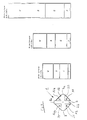
- the arrangement according to the invention uses depot containers (1) which have a polygonal plan (2).
- This layout has alternating short sides (3, 4) and long sides (5, 6).
- the sides have the same dimensions, i.e. the short sides (3, 4) are the same among themselves, while the long sides (5, 6) have the same length.
- Fixed container walls (7, 8) and (7a and 7b) extend over the short polygon sides (3, 4).
- These are provided with guides (9, 10) for the movable walls (11, 12 and 11 a, 12a) arranged over the longer polygon sides (5, 6).
- these walls are provided with vertical beads (13) and can be moved vertically upwards and downwards in the guides (9, 10) according to the arrow (14) in FIG. 2.
- the reduced representation of the depot container (1) in FIG. 6 shows the division of the container interior by the chambers.
- Behind the chamber wall labeled (7) i.e. the actual sorting device is located behind an opening (15) which is surrounded by a three-sided screen (16) to avoid misuse. It is known and therefore need not be described in detail. Hollow waste glass, e.g. Bottles or other glass containers are thrown in individually, sorted optoelectronically by color and tipped into the chambers from above, causing the glass to be broken. Under the opening (15) there is another opening (17) through which other waste from non-glass can be introduced into the container. Behind the chamber walls (7, 7a; 8, 8a) there are vertical walls which separate the chambers in the container from one another.
- the chambers (18, 19) which are furthest away from the insertion opening (15) in the container are intended for stained glass, namely the chamber (18) for green glass and the chamber (19) for amber glass.
- the chambers (20, 21) closest to and in front of the insertion opening are intended for white glass.
- the chambers (18-21) have the same volume. The division of the chambers into the sorted glass takes account of the fact that white glass accounts for the vast majority of the collected hollow glass.
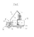
- the arrangement according to the invention also includes a collector, which is generally designated (23) in FIG. 5 and consists of a container (24) on a platform (25) of a truck (26).
- the container can be unloaded from and loaded onto the platform (25).
- a construction crane (28) is arranged behind the driver's cab (27) and has a height-adjustable crane column (29) with a boom (30) articulated thereon.
- the boom consists of two sections (31, 32) which can be telescoped and pivoted together on the crane column and in joints. The hydraulic drives required for this are not shown.
- a receptacle (33) (Fig. 3).
- This carries in a head (34), which can be placed over a fixed on the container (1) suspension (35), a horizontal locking bolt (36), which is also provided with a hydraulic drive, not shown.
- the direction in which the head (34) is placed over the suspension (35) of the container is marked with an arrow in FIG. 3.
- This movement is carried out with the boom (30), i.e. in particular with the end boom (32) according to the direction of the arrow (37).
- the head is actually seated on the movable part (38) of a rotating mechanism (39).
- the fixed part has a cantilever arm (40) balanced with a counterweight (40a), at the end of which a lifting mechanism (41) is attached.
- the lifting mechanism consists of a hydraulic cylinder (42), the piston rod (43) of which forms the movable part of the lifting mechanism (41) carries a tool (44) which is inserted into a receptacle (45) by actuating the rotating mechanism (39) can be engaged.
- These receptacles (45) are provided on each chamber wall, as shown at (46-50) in Fig. 1.
- each receptacle is a section of a U-profile (51) which is screwed to the relevant chamber wall with a profile leg (52) and whose opposite profile leg (53) with a flange (54) of the tool (44 ) can become form-fitting.
- an upper flange (57) is hydraulically movable, with which the upper profile leg (53) can be clamped.
- the movable chamber walls (12, 13) can be seen with the lifting mechanism (41) shown in FIGS. 3 and 4 and described above in accordance with the angle of rotation in the rotating mechanism (39) by extending and retracting the piston rod (43) into the Open and close the cylinder (42) individually. Since, as can be seen from FIG. 5, the chambers are designed as inclined floor emptiers, the fragments contained in the chambers slide out automatically when the chamber wall is open and are retained when the chamber wall is closed.
- the collector (23), as shown in Fig. 5, is divided into compartments FGBW.
- F stands for non-glass (foreign substances)
- G for green glass
- B for amber glass
- W for white glass.
- the volumes of the compartments become larger or smaller.
- the division is always in the same ratio, so that the compartment for white glass is the compartment with the largest volume.
- the volume for this is followed by the compartment for green glass, the compartment for amber glass and the compartment for non-glass (foreign matter), each with a lower content, the latter compartment having the smallest volume.
- This gradation in the volume of the compartments is independent of the layout of the chambers.
- the drives of the crane described above in connection with FIGS. 3 to 5, ie the boom drives, and the drives of the locking bolt (36) of the rotating mechanism (39) and the lifting mechanism (41) are connected to one another by a program control.
- the boom with its receptacle (33) is pivoted over the suspension (35) and then lowered, so that the head (34) slips over the suspension (35).
- the bolt (36) is moved hydraulically into the locking position, whereby the container is positively connected to the bolt.
- the tool (44) is now engaged in the receptacle (45) with the aid of the arm (40).
- the piston rod (43) is extended and the receptacle (45) is positively connected to the tool.
- the program control now moves the container over the collector (23), whereby according to the exemplary embodiment according to FIG. 5 the chamber (19), which contains amber glass, is emptied into the assigned compartment B, in which the chamber assigned to it is pulled up.
- the piston rod (43) is inserted into the cylinder (42).
- the piston rod is extended again and the chamber wall is closed.
- the container is then moved over the following compartment with the help of the boom (30) by actuating the boom section drives, the lifting mechanism (41) is unleashed with the help of the rotating mechanism (40a) and is re-engaged in the receptacle (45) of the following chamber wall.
Landscapes
- Engineering & Computer Science (AREA)
- Mechanical Engineering (AREA)
- Refuse-Collection Vehicles (AREA)
- Processing Of Solid Wastes (AREA)
- Jib Cranes (AREA)
Applications Claiming Priority (2)
| Application Number | Priority Date | Filing Date | Title |
|---|---|---|---|
| DE4018424 | 1990-06-08 | ||
| DE19904018424 DE4018424A1 (de) | 1990-06-08 | 1990-06-08 | Anordnung zum verladen von nach farben sortierten hohlglaesern |
Publications (1)
| Publication Number | Publication Date |
|---|---|
| EP0464253A1 true EP0464253A1 (fr) | 1992-01-08 |
Family
ID=6408066
Family Applications (1)
| Application Number | Title | Priority Date | Filing Date |
|---|---|---|---|
| EP19900114004 Withdrawn EP0464253A1 (fr) | 1990-06-08 | 1990-07-21 | Dispositif pour le chargement de verre creux après son tri selon la couleur |
Country Status (2)
| Country | Link |
|---|---|
| EP (1) | EP0464253A1 (fr) |
| DE (1) | DE4018424A1 (fr) |
Cited By (6)
| Publication number | Priority date | Publication date | Assignee | Title |
|---|---|---|---|---|
| WO1994005568A1 (fr) * | 1992-08-31 | 1994-03-17 | Stevelift Pty Ltd | Camion a ordures/matieres recyclables |
| WO1996039347A3 (fr) * | 1995-06-03 | 1997-01-23 | Peters Klaus Tilmann | Systeme collecteur pour produits destines au recyclage |
| EP0790194A1 (fr) * | 1996-02-09 | 1997-08-20 | Antonio Ramis Rubio | Véhicule pour le ramassage et le compactage des ordures |
| EP0921080A1 (fr) * | 1997-12-03 | 1999-06-09 | Der Grüne Punkt-Duales System Deutschland Aktiengesellschaft | Conteneur à verre |
| AT13010U1 (de) * | 2012-03-21 | 2013-04-15 | Waizinger Gottfried Ing | Fahrzeugaufbau mit einer Sammelmulde für Altglas |
| CN113788632A (zh) * | 2021-09-30 | 2021-12-14 | 肇庆瑞利辉玻璃科技有限公司 | 一种家具用夹胶玻璃及其使用方法 |
Families Citing this family (2)
| Publication number | Priority date | Publication date | Assignee | Title |
|---|---|---|---|---|
| DE4218742A1 (de) * | 1992-06-04 | 1993-12-09 | Dbf Dienstleistung Fuer Behael | System zur Entsorgung von Altstoffen |
| CN109606978B (zh) * | 2019-01-08 | 2021-12-24 | 广西御卓环保科技有限公司 | 道路垃圾环保处理装置及其施工方法 |
Citations (5)
| Publication number | Priority date | Publication date | Assignee | Title |
|---|---|---|---|---|
| FR2311683A1 (fr) * | 1975-04-29 | 1976-12-17 | Sempere Const Hydro Meca Benne | Benne vide-bac |
| EP0054463A1 (fr) * | 1980-12-17 | 1982-06-23 | Gerard Dorey | Installation pour la récupération des ordures ménagères |
| DE8616325U1 (de) * | 1986-06-18 | 1986-07-31 | C. F. Maier GmbH & Co, 7923 Königsbronn | Vorrichtung zum Entleeren von Großbehältern |
| BE905461A (nl) * | 1986-09-19 | 1987-03-19 | Kotrac Internat N V | Werkwijze voor het ophalen en verwerken van afval, inrichting voor de toepassing van deze werkwijzen en produkten verkregen uit dat afval. |
| EP0334987A2 (fr) * | 1988-03-26 | 1989-10-04 | Mabeg Müll- und Abfallbeseitigungs- gesellschaft mbH & Co. oHG. | Collecteur de déchets de verre concave pourvu d'un dispositif de séparation et de tri selon la couleur |
Family Cites Families (3)
| Publication number | Priority date | Publication date | Assignee | Title |
|---|---|---|---|---|
| DE3413937A1 (de) * | 1983-09-01 | 1985-03-21 | Fa. Heinz Grumbach, 4834 Harsewinkel | Anordnung zum betaetigen eines klappbehaelters |
| DE3600603A1 (de) * | 1986-01-11 | 1986-09-18 | Konrad Eduard 82049 Pullach Matulla | Hausmuelleimer mit kippbaren behaelterzellen fuer wertmuelltrennung / recycling-ablaeufe |
| DE8805173U1 (de) * | 1988-04-19 | 1988-06-09 | Fritz Schäfer GmbH, 5908 Neunkirchen | Klappbehälter |
-
1990
- 1990-06-08 DE DE19904018424 patent/DE4018424A1/de active Granted
- 1990-07-21 EP EP19900114004 patent/EP0464253A1/fr not_active Withdrawn
Patent Citations (5)
| Publication number | Priority date | Publication date | Assignee | Title |
|---|---|---|---|---|
| FR2311683A1 (fr) * | 1975-04-29 | 1976-12-17 | Sempere Const Hydro Meca Benne | Benne vide-bac |
| EP0054463A1 (fr) * | 1980-12-17 | 1982-06-23 | Gerard Dorey | Installation pour la récupération des ordures ménagères |
| DE8616325U1 (de) * | 1986-06-18 | 1986-07-31 | C. F. Maier GmbH & Co, 7923 Königsbronn | Vorrichtung zum Entleeren von Großbehältern |
| BE905461A (nl) * | 1986-09-19 | 1987-03-19 | Kotrac Internat N V | Werkwijze voor het ophalen en verwerken van afval, inrichting voor de toepassing van deze werkwijzen en produkten verkregen uit dat afval. |
| EP0334987A2 (fr) * | 1988-03-26 | 1989-10-04 | Mabeg Müll- und Abfallbeseitigungs- gesellschaft mbH & Co. oHG. | Collecteur de déchets de verre concave pourvu d'un dispositif de séparation et de tri selon la couleur |
Cited By (7)
| Publication number | Priority date | Publication date | Assignee | Title |
|---|---|---|---|---|
| WO1994005568A1 (fr) * | 1992-08-31 | 1994-03-17 | Stevelift Pty Ltd | Camion a ordures/matieres recyclables |
| WO1996039347A3 (fr) * | 1995-06-03 | 1997-01-23 | Peters Klaus Tilmann | Systeme collecteur pour produits destines au recyclage |
| EP0790194A1 (fr) * | 1996-02-09 | 1997-08-20 | Antonio Ramis Rubio | Véhicule pour le ramassage et le compactage des ordures |
| EP0921080A1 (fr) * | 1997-12-03 | 1999-06-09 | Der Grüne Punkt-Duales System Deutschland Aktiengesellschaft | Conteneur à verre |
| AT13010U1 (de) * | 2012-03-21 | 2013-04-15 | Waizinger Gottfried Ing | Fahrzeugaufbau mit einer Sammelmulde für Altglas |
| CN113788632A (zh) * | 2021-09-30 | 2021-12-14 | 肇庆瑞利辉玻璃科技有限公司 | 一种家具用夹胶玻璃及其使用方法 |
| CN113788632B (zh) * | 2021-09-30 | 2023-05-16 | 肇庆瑞利辉玻璃科技有限公司 | 一种家具用夹胶玻璃及其使用方法 |
Also Published As
| Publication number | Publication date |
|---|---|
| DE4018424C2 (fr) | 1992-05-21 |
| DE4018424A1 (de) | 1991-12-12 |
Similar Documents
| Publication | Publication Date | Title |
|---|---|---|
| DE3123161C2 (fr) | ||
| EP0464253A1 (fr) | Dispositif pour le chargement de verre creux après son tri selon la couleur | |
| EP0166072A1 (fr) | Conteneur pour la collecte de produits ré-utilisables | |
| EP0334987B1 (fr) | Collecteur de déchets de verre concave pourvu d'un dispositif de séparation et de tri selon la couleur | |
| DE2937727A1 (de) | Anlage zum verdichten von festkoerperladungen in einem behaelter | |
| DE4441551C1 (de) | Vorrichtung zum hängenden Anheben und Entleeren von Behältern, Containern od. dgl. | |
| DE3917307C1 (en) | Refuse collection truck with lifting beam - incorporates outrigger arms and elevator platform on trolley frame | |
| DE4237226A1 (de) | Einrichtung zum Entleeren von Sammelbehälter | |
| DE3721672C2 (fr) | ||
| DE60105121T2 (de) | Vorrichtung zum Entleeren eines Fasses | |
| DE4218742A1 (de) | System zur Entsorgung von Altstoffen | |
| DE3029982A1 (de) | Sammelbehaelter, insbesondere fuer altglas | |
| DE3640132A1 (de) | Muellfahrzeugaufbau | |
| EP0835215B1 (fr) | Dispositif destine au vidage automatique d'un conteneur | |
| DE10042800A1 (de) | Verfahren und Vorrichtung zum Betreiben eines Abfallsammelfahrzeuges und ein entsprechendes Fahrzeug zur Durchführung des Verfahrens | |
| DE4017544A1 (de) | Behaelter mit bodenklappe | |
| DE10162377A1 (de) | Fahrzeug zum Aufnehmen und Transportieren von Sperrgut | |
| DE19952483C1 (de) | Verriegelungsvorrichtung für nebeneinander angeordnete Hubwagen | |
| DE9201348U1 (de) | Abfallbehälter | |
| DE1258345B (de) | Geraet zum Umladen von schuett- und fliessfaehigem Material | |
| EP0819623B1 (fr) | Dispositif pour décharger des poubelles de grande dimension | |
| EP2524881B1 (fr) | Véhicule pour déchets avec trémie de chargement et un dispositif de commande destiné au blocage d'une zone partielle | |
| DE2807046C3 (de) | Anlage zum Beschicken von Speicherbehältern mit Schüttgut | |
| EP0445637B1 (fr) | Dispositif pour remplir une benne de matériaux en vrac | |
| DE4142307A1 (de) | Verfahren zur steuerung einer schuettvorrichtung sowie schuettvorrichtung zum entleeren von muellbehaeltern in den schuettraum eines muellfahrzeugs |
Legal Events
| Date | Code | Title | Description |
|---|---|---|---|
| PUAI | Public reference made under article 153(3) epc to a published international application that has entered the european phase |
Free format text: ORIGINAL CODE: 0009012 |
|
| AK | Designated contracting states |
Kind code of ref document: A1 Designated state(s): AT BE CH DE DK ES FR GB GR IT LI LU NL SE |
|
| 17P | Request for examination filed |
Effective date: 19920305 |
|
| 17Q | First examination report despatched |
Effective date: 19930416 |
|
| STAA | Information on the status of an ep patent application or granted ep patent |
Free format text: STATUS: THE APPLICATION IS DEEMED TO BE WITHDRAWN |
|
| 18D | Application deemed to be withdrawn |
Effective date: 19930827 |