EP0464411A1 - Dispositif pour la production de tuyaux en matière plastique - Google Patents
Dispositif pour la production de tuyaux en matière plastique Download PDFInfo
- Publication number
- EP0464411A1 EP0464411A1 EP91109580A EP91109580A EP0464411A1 EP 0464411 A1 EP0464411 A1 EP 0464411A1 EP 91109580 A EP91109580 A EP 91109580A EP 91109580 A EP91109580 A EP 91109580A EP 0464411 A1 EP0464411 A1 EP 0464411A1
- Authority
- EP
- European Patent Office
- Prior art keywords
- mold
- vacuum
- section
- axis
- mold space
- Prior art date
- Legal status (The legal status is an assumption and is not a legal conclusion. Google has not performed a legal analysis and makes no representation as to the accuracy of the status listed.)
- Granted
Links
Images




Classifications
-
- B—PERFORMING OPERATIONS; TRANSPORTING
- B29—WORKING OF PLASTICS; WORKING OF SUBSTANCES IN A PLASTIC STATE IN GENERAL
- B29C—SHAPING OR JOINING OF PLASTICS; SHAPING OF MATERIAL IN A PLASTIC STATE, NOT OTHERWISE PROVIDED FOR; AFTER-TREATMENT OF THE SHAPED PRODUCTS, e.g. REPAIRING
- B29C49/00—Blow-moulding, i.e. blowing a preform or parison to a desired shape within a mould; Apparatus therefor
- B29C49/0015—Making articles of indefinite length, e.g. corrugated tubes
- B29C49/0021—Making articles of indefinite length, e.g. corrugated tubes using moulds or mould parts movable in a closed path, e.g. mounted on movable endless supports
- B29C49/0022—Making articles of indefinite length, e.g. corrugated tubes using moulds or mould parts movable in a closed path, e.g. mounted on movable endless supports characterised by mould return means
-
- B—PERFORMING OPERATIONS; TRANSPORTING
- B29—WORKING OF PLASTICS; WORKING OF SUBSTANCES IN A PLASTIC STATE IN GENERAL
- B29C—SHAPING OR JOINING OF PLASTICS; SHAPING OF MATERIAL IN A PLASTIC STATE, NOT OTHERWISE PROVIDED FOR; AFTER-TREATMENT OF THE SHAPED PRODUCTS, e.g. REPAIRING
- B29C2791/00—Shaping characteristics in general
- B29C2791/004—Shaping under special conditions
- B29C2791/006—Using vacuum
-
- Y—GENERAL TAGGING OF NEW TECHNOLOGICAL DEVELOPMENTS; GENERAL TAGGING OF CROSS-SECTIONAL TECHNOLOGIES SPANNING OVER SEVERAL SECTIONS OF THE IPC; TECHNICAL SUBJECTS COVERED BY FORMER USPC CROSS-REFERENCE ART COLLECTIONS [XRACs] AND DIGESTS
- Y10—TECHNICAL SUBJECTS COVERED BY FORMER USPC
- Y10S—TECHNICAL SUBJECTS COVERED BY FORMER USPC CROSS-REFERENCE ART COLLECTIONS [XRACs] AND DIGESTS
- Y10S425/00—Plastic article or earthenware shaping or treating: apparatus
- Y10S425/06—Vacuum
Definitions
- the invention relates to a device for the production of plastic pipes, in which half-molds, which are provided with a mold recess and are complemented on a molding line in pairs to form a mold with a mold space axis, are arranged in a circuit on a machine table, with at least two half-molds complementing one another have a mold space section for producing a special profile section of the tube, the molding section being preceded by a spray head of an extruder, the half molds being provided with vacuum channels connected to the respective mold recess, which open into the vacuum section formed in the machine table and which over Open the vacuum slots in the mold recess.
- Such a device is known from DE-PS 12 55 292.
- Such devices can be used to produce tubes, so-called corrugated tubes, with transverse grooves, namely circular grooves, as described in EP-A1-0 065 729 (corresponding to US 4,492,551).
- corrugated tubes provided with helical transverse grooves can be produced, as shown in DE-PS 12 42 848.
- ribs can be provided, as can be seen in DE-PS 37 01 822.
- the transverse grooves or ribs are formed in a vacuum process, i.e. Via vacuum slots acted upon by vacuum, which are at least predominantly arranged transversely to the direction of the mold space axis.
- tubes with flexible sections can also be produced on the device according to DE-PS 12 55 292.
- the pipes described can be designed as composite pipes with an additional inner pipe.
- the invention is therefore based on the object of designing a device of the generic type in such a way that even special profile sections with profiles that can be at least partially calibrated can be produced in a vacuum process with high accuracy and high quality.
- the mold space section has surfaces oriented at least partially in the direction of the mold space axis and in that at least one vacuum slot in the area of these surfaces runs at least predominantly parallel to the mold space axis and, in relation to the mold space axis, is the most radial of it distant area opens into the mold space.
- vacuum we mean an air pressure that is less than atmospheric pressure.
- Surfaces are not necessarily flat surfaces, but also curved surfaces.
- the vacuum slots do not necessarily have to be continuous; they can also be formed by short vacuum slots or rows of holes arranged one behind the other in one direction; their orientation is decisive, at least predominantly parallel to the mold space axis.
- the aim aimed at according to the invention is naturally also achieved if the at least one vacuum slot opens into the molding space in the immediate vicinity of the region that is the furthest radially from the axis of the molding space. If there are precisely defined butting edges, which have a relative maximum distance from the mold space axis, between surfaces of the respective half-mold, then the respective vacuum slot opens into this butting edge.
- the vacuum application can be improved, with the result that the shaping is further improved.
- the vacuum slots have a width of less than or equal to 0.5 mm in a known manner to ensure that when the tube is formed, the still warm plastic is not drawn into the vacuum slots.
- the measures according to the invention primarily only ensure that a complete, flat contact of the still warm plastic hose for producing a tube is achieved on the surfaces or the wall of the corresponding mold space section.
- a device for producing plastic pipes with transverse grooves has a machine table 1 on which half molds 2 and 2 'are arranged, each of which is connected to one another to form so-called chains 3 and 3'.
- a tab 5 is articulated on each half mold 2 or 2 'in its outer area 4, which is at the front in the direction of production 4, by means of a pivot pin 6, which is also attached to the corresponding point of the subsequent half mold 2 or 2' by means of such a pivot bolt 6.
- the chains 3, 3 'formed in this way are guided at their rear end, seen in the direction of production 4, via deflection wheels serving as so-called infeed rollers 7.
- the individual half molds 2, 2 ' are pivoted into a mold section 9 in accordance with the direction of rotation arrows 8 and 8' during the rotation of the chains 3, 3 ', in which two half molds 2, 2' are combined to form a pair of molds, again in the production direction 4 successive pairs of molds lie close together.
- so-called closing rollers 10 are provided which accelerate the rear ends of the half molds 2, 2' in the production direction 4.
- a toothing 16 is formed, the two toothings 16 of the paired half molds 2, 2' being aligned with one another, so that from above a common drive pinion 17 can engage in this toothing 16, which the half molds 2, 2 'in the mold section 9 as a closed mold pushes through the mold section 9.
- This drive pinion 17 is driven in the usual manner by a motor (not shown) via a drive gear 18 which is fixed in a rotationally fixed manner on a shaft 19 which in turn carries the drive pinion 17.
- the shaft 19 is mounted in a bearing block 20 which is supported and spaced apart by means of distance prisms 21 from the machine table the latter is firmly connected by means of screws 22.
- the tubes 23 are described in more detail below.
- an extruder is provided, of which only the spray head 25 is indicated, from which an invisible hose is extruded, which, while still in a hot-plastic state, runs into the mold formed in the molding section 9, in which, among other things, the transverse profile is formed.
- the device described so far is known, for example from EP-A-0 065 729. With this device, so-called composite pipes can be produced in the same way, which externally are the same as the pipe 23 and on the inside are integrally formed with a continuously smooth pipe.
- the molding recesses 27, 27 'formed in the half molds 2, 2' to form a molding space 26 have a shape which is complementary to the outer shape of the tube 23. They are provided with vacuum channels 28, 28 'which run in the vicinity of the wall of the mold recess 27 or 27' and enclose them at a relatively small distance in the case of half molds 2, 2 'which are adjacent to one another. From the vacuum channels 28, 28 ', numerous vacuum slots, to be described further below, open into the mold recess 27 or 27'.
- the vacuum channels 28, 28 ' are connected to one another in the case of half molds 2, 2' lying against one another, as can be seen from FIG. 2.
- the vacuum channels 28 and 28 ' open into the underside 29 and 29' of the half molds 2, 2 'resting on the machine table 1.
- the air flow in the vacuum channels 28, 28 'and at the vacuum connections 30, 30' is indicated by directional arrows 31.
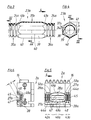
- the tube 23a shown in FIGS. 3 and 4 has tube sections 35a and 36a which have been produced in the usual manner already described above and which are provided with transverse grooves 24a.
- a special profile section 37a is formed between the two sections 35a and 36a and has a polygonal cross section, in the present case a regular hexagonal cross section.
- the section 37a thus has a plurality of, in the specific case six, outer surfaces 39 which run parallel to the pipe axis 38 and thus to the production direction 4 and which in each case abut profile edges 40 and which therefore also run parallel to the pipe axis 38.
- the distance a between these profile edges 40 and the tube axis 38 is - based on the two outer surfaces 39 adjoining each profile edge 40, the maximum distance from the tube axis 38.
- a transition area 41a a is formed between the area of the special profile section 37a delimited by the outer surfaces 39 and the adjacent sections 35a and 36a.
- a half mold 2a is shown, as it is used to form the tube sections 35a, 36a and the intermediate profile section 37a of a tube 23a. It has mold space sections 42a and 43a which have mold recesses 27a corresponding to the cross section of the transverse grooves 24a.
- vacuum slots 44a are provided in a conventional manner, which are connected to the vacuum channels 28a and which each open into the region of the transverse grooves 24a, which is the most radially outer in relation to the tube axis 38, in these. This can be seen in particular from FIG. 5.
- the pipe axis 38 corresponds to the mold space axis 45.
- the vacuum slots 44a run transversely, that is to say at a right angle, to the direction of the mold space axis 45.
- a mold space section 46a is formed, which is used to mold the special profile section 37a. It has molded walls 47 which are used to shape the outer surfaces 39. At the abutting edges 48 or in the immediate vicinity of two such adjacent mold walls 47, vacuum slots 49a open into the mold space section 46a, which are also connected to at least one vacuum channel 28a. These vacuum slots 49a thus run parallel to the profile edges 40 to be produced, ie parallel to the mold space axis 45, as the course of the vacuum slots 49a in FIG. 5 shows, these are cut into the half mold 2a with a disk milling cutter.
- the radial distance a of the vacuum slots 49 from the mold space axis 45 is therefore the greatest radial distance that a region of the mold wall 47 has from the mold space axis 45 has. A good, uniform, clean shape of the special profile section 37a is thus ensured.
- Separate vacuum slots are not always provided in the mold space sections 50a provided for shaping the transition regions 41. In this exemplary embodiment, the evacuation takes place via the vacuum slots 49a, since these are also located radially outermost in relation to these mold space sections 50a - in relation to the mold space axis 45.
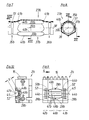
- a tube 23b is shown, which is partially formed in a half mold 2b according to FIGS. 9 and 10. It has pipe sections 35b and 36b, between which a special profile section 37b is formed, each of which merges into the pipe section 35b or 36b by means of a transition region 41b.
- the pipe sections 35b and 36b are basically smooth-walled, that is to say they have a profile that can be calibrated, as could also be produced, for example, by extrusion. They each have a constriction 51 which is approximately semicircular in cross section just before the transition region 41b. The constrictions 51 run transversely, that is to say perpendicularly, to the tube axis 38.
- the special profile section 37b is of identical design to the special profile section 37a in the exemplary embodiment according to FIGS. 3 and 4. The same reference numbers are therefore added without further description for the same parts ab used.
- the mold space section 46b used to form the special profile section 37b is identical to the mold space section 46a according to FIGS. 5 and 6. 8 and 9, the same parts are therefore designated with the same reference number, which is supplemented by ab, without the need for a new description.
- the distance b between the mold space axis 45 and the abutting edge 48b what has been said above about the distance a applies.
- FIG. 11 and 12 show the section of a tube 23c which is of identical design over its entire length and which therefore has a special profile section throughout. It has transverse grooves 24c which only extend in sections in the circumferential direction. Between the transverse grooves 24c are formed in the longitudinal direction of the tube 23c and parallel to the tube axis 38 extending in cross-section according to FIG. 12 approximately rectangular, that is to say a total of approximately cuboid, uninterrupted elevations 57. These elevations 57 each have two side surfaces 58, which run approximately parallel to a radius to the pipe axis 38, and an outer surface 59, which runs transversely thereto and transversely to the pipe axis 38.
- outer surfaces 59 protrude slightly radially beyond the transverse grooves 24c, so that the outer surfaces 59 of a plurality of tubes 23c can be placed against one another on these outer surfaces 59 and stacked with their tube axes 38 arranged in parallel.
- channels are formed between the abutting elevations 57, that is to say in the region of the transverse grooves 24c.
- the use of such tubes 23c is therefore conceivable for heat exchangers, in the same way as that according to FIGS. 3, 4 and 7,8.
- a half mold 2c which can be used for producing the tube 23c according to FIGS. 11 and 12 has suitable recesses 27c for producing the transverse grooves 24c, which are connected to vacuum channels 28c via vacuum slots 44c.
- these vacuum slots 44c extend over the full semi-cylindrical circumference of the molding space 26c of the half mold 2c. They run transversely to the mold space axis 45.
- the half mold 2c is furthermore provided with recesses 60 which serve to form the elevations 57 and which have corresponding side walls 61 for forming the side surfaces 58 and an outer wall 62 for forming the outer surface 59.
- Individual vacuum slots 49c are formed on the abutting edges 63 between a respective side wall 61 and an outer wall 62, which thus run parallel to the mold space axis 45. They are connected directly to the vacuum slots 44c and each connected to a vacuum channel 28c. The vacuum slots 49c, which are arranged one after the other and are assigned to a butt edge 63, are therefore not connected to one another.
- the radial distance c from the mold space axis 45 to a vacuum slot 49c is the greatest possible radial distance based on the respective distance between the adjacent regions of the side walls 61 and the outer wall 62 from the mold space axis 45, so that this is used to form the side surfaces 58 and the outer surface 59 of an elevation 57, the necessary vacuum is applied at the radially outermost point in relation to the mold space axis 45.
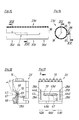
- the tube shown in Figs. 15 and 16 23d has purely cylindrical tube sections 35d and 36d, between which a special profile section 37d is arranged. It has a cylindrical region which is identical to that of the tube sections 35d and 36d. From this, an elevation 64 rises radially outwards, which is delimited by side surfaces 65 and an outer surface 66, in a manner similar to the elevation 57 of the exemplary embodiment according to FIGS. 11 and 12, only this elevation 64 being located only over a certain special profile section 37d extends parallel to the tube axis 38.
- the half mold 2d shown in FIGS. 17 and 18, used to manufacture the tube according to FIGS. 15 and 16, has an essentially cylindrical mold recess 27d, with mold space sections 42d and 43d including a mold space section 46d between them.
- the mold space sections 42d and 43d are cylindrical.
- Vacuum slots 44d open into them and are connected to vacuum channels 28d.
- the vacuum slots 44d run - as is generally customary - transversely to the mold space axis 45.
- a groove-like recess 67 which is parallel to the mold space axis 45 and is adapted in cross section to the elevation 64 is formed in the mold space section 46d. It has side walls 68 and an outer wall 69 for shaping the side surfaces 65 and the outer surface 66.
- a vacuum slot 49d opens into the recess 67 at the abutting edge 70 between a side wall 68 and the outer wall 69. These vacuum slots 49d are in turn connected to a vacuum channel 28e. It also applies here that the radial distance d of the abutting edges 70 running parallel to the mold space axis 45 is the maximum radial distance of the outer wall 69 or side walls 68 from the mold space axis 45.
- the pipe 23e according to FIGS. 19 and 20 differs from the pipe 23d according to FIGS. 15 and 16 only in that an elevation 71 is provided which differs from the elevation 64. Otherwise, all reference numerals from FIGS. 15, 16, to which an e has been added, are used without the need for a new description.
- the elevation 71 has a side surface 72 running parallel to the pipe axis 38 and a side surface 73 running at an acute angle k to the pipe axis 38.
- the elevation 71 is closed to the outside by an outer surface 74.
- the angle k is in any case less than 30 and preferably 10 to 20 °.
- FIGS. 21, 22 The half mold which can be used to produce the tube 23e according to FIGS. 19, 20 is shown in FIGS. 21, 22.
- the same reference numerals are used as in FIGS. 11, 18, which are followed by an e.
- a recess 75 is provided which extends radially away from the mold recess 27e and has two side walls 76, 77 for the formation of the side surfaces 72, 73 and an outer wall 78 for the formation of the outer surface 74.
- the two side walls 76, 77 which meet at an acute angle at the angle k are still connected to one another by a short transverse wall 79 which runs transversely to the mold space axis 45 and serves to form a corresponding transverse surface 80 which connects the side surfaces 72, 73.
- a vacuum slot 49e is formed on the abutting edge 81 between the side wall 76 and the outer wall 78 of the recess 75 and is connected in a conventional manner to a vacuum channel 28e.
- This vacuum slot 49e extends parallel to the mold space axis 45.
- a vacuum slot 83 is formed, which likewise forms the angle k with the vacuum slot 49e and which is also connected to the vacuum channel 28e, as in particular 22 emerges.
- a vacuum slot 85 is also formed on the abutting edge 84 between the transverse wall 79 and the outer wall 78, which therefore runs transverse to the mold space axis 45 and is also connected to its own vacuum channel 28e.
- the distance e of the abutting edges 81, 82, 84 and thus the distance of the vacuum slots 49e, 83, 85 from the mold space axis 45 is the relatively largest distance of the recess 75 from the mold space axis 45.
- FIGS. 23 and 24 largely corresponds to that according to FIGS. 9 and 10.
- the same reference numerals are therefore used without further description, to which an f is added.
- the tube which is produced using the half mold 2f according to FIGS. 23 and 24 is identical to that according to FIGS. 7 and 8, so that it does not need to be shown again in the drawing.
- the only difference with the half mold 2f compared to the half mold 2b is that the vacuum slots 49f do not extend over the full length of the mold space section 46f, but only over a central section, as can be seen in FIG. 23.
- This central vacuum slot 49f is followed by additional vacuum slots 86, 87 to form space section 50f, each of which is connected to its own vacuum channel 28f and which is not connected to vacuum slot 49f.
- These vacuum slots 49f and 86, 87 likewise run parallel to the molding space axis 45. This separation of the vacuum slots running parallel to the molding space axis 45 and arranged one behind the other in the production direction 4 leads to an improvement in the shaping.
Landscapes
- Engineering & Computer Science (AREA)
- Manufacturing & Machinery (AREA)
- Mechanical Engineering (AREA)
- Blow-Moulding Or Thermoforming Of Plastics Or The Like (AREA)
- Moulds For Moulding Plastics Or The Like (AREA)
- Extrusion Moulding Of Plastics Or The Like (AREA)
- Casting Or Compression Moulding Of Plastics Or The Like (AREA)
Applications Claiming Priority (2)
| Application Number | Priority Date | Filing Date | Title |
|---|---|---|---|
| DE4021564A DE4021564A1 (de) | 1990-07-06 | 1990-07-06 | Vorrichtung zur herstellung von kunststoff-rohren |
| DE4021564 | 1990-07-06 |
Publications (2)
| Publication Number | Publication Date |
|---|---|
| EP0464411A1 true EP0464411A1 (fr) | 1992-01-08 |
| EP0464411B1 EP0464411B1 (fr) | 1994-08-24 |
Family
ID=6409790
Family Applications (1)
| Application Number | Title | Priority Date | Filing Date |
|---|---|---|---|
| EP91109580A Expired - Lifetime EP0464411B1 (fr) | 1990-07-06 | 1991-06-11 | Dispositif pour la production de tuyaux en matière plastique |
Country Status (6)
| Country | Link |
|---|---|
| US (1) | US5141427A (fr) |
| EP (1) | EP0464411B1 (fr) |
| JP (1) | JP3016628B2 (fr) |
| CA (1) | CA2045354C (fr) |
| DE (2) | DE4021564A1 (fr) |
| ES (1) | ES2060247T3 (fr) |
Cited By (3)
| Publication number | Priority date | Publication date | Assignee | Title |
|---|---|---|---|---|
| FR2748417A1 (fr) * | 1996-05-09 | 1997-11-14 | Corelco | Installation pour la fabrication par depression de corps tubulaires en matiere synthetique |
| EP0909629A1 (fr) * | 1997-10-15 | 1999-04-21 | Corelco | Installation pour la fabrication par dépression de corps tubulaires en matière synthétique |
| EP0648158B2 (fr) † | 1992-06-15 | 2004-12-29 | LUPKE, Manfred Arno Alfred | Moule mobile de moulage a cavites multiples pour le moulage de tubes profiles et blocs de moulage |
Families Citing this family (9)
| Publication number | Priority date | Publication date | Assignee | Title |
|---|---|---|---|---|
| DE4111228A1 (de) * | 1991-04-08 | 1992-10-15 | Wilhelm Hegler | Vorrichtung zur herstellung von kunststoff-rohren |
| DE4210482A1 (de) * | 1992-03-31 | 1993-10-07 | Wilhelm Hegler | Verfahren und Vorrichtung zur fortlaufenden Herstellung eines Verbundrohres mit Rohr-Muffe |
| US5460771A (en) * | 1992-10-16 | 1995-10-24 | Itt Corporation | Process for producing corrugated multi-layer tubing having layers of differing plastic characteristics |
| DE19702647C1 (de) * | 1997-01-25 | 1998-02-26 | Unicor Rohrsysteme Gmbh | Vorrichtung zum Herstellen von Querrippen-Rohren |
| US5960977A (en) * | 1998-05-14 | 1999-10-05 | Itt Manufacturing Enterprises, Inc. | Corrugated polymeric filler neck tubing |
| US6240970B1 (en) | 1999-04-01 | 2001-06-05 | Itt Manufacturing Enterprises, Inc. | Tubing for handling hydrocarbon materials and having an outer jacket layer adhered thereto |
| DE19916641C2 (de) * | 1999-04-14 | 2002-09-05 | Unicor Rohrsysteme Gmbh | Vorrichtung zur Herstellung eines in seiner Längsrichtung öffenbaren und wiederverschließbaren Wellrohres |
| US6276400B1 (en) | 1999-06-08 | 2001-08-21 | Itt Manufacturing Enterprises, Inc. | Corrosion resistant powder coated metal tube and process for making the same |
| DE102015115828A1 (de) * | 2015-09-18 | 2017-03-23 | Unicor Gmbh | Vorrichtung zum Herstellen von Kunststoffrohren |
Citations (5)
| Publication number | Priority date | Publication date | Assignee | Title |
|---|---|---|---|---|
| DE1242848B (de) * | 1963-09-21 | 1967-06-22 | Wilhelm Hegler | Vorrichtung zum Herstellen von Rohren mit Querrillen aus thermoplastischem Kunststoff |
| US4003685A (en) * | 1974-10-09 | 1977-01-18 | Maroschak Ernest J | Apparatus for molding plastic pipe with enlarged portions formed therein |
| US4319872A (en) * | 1976-12-01 | 1982-03-16 | Lupke Gerd Paul Heinrich | Apparatus for producing thermoplastic tubing |
| WO1988005377A1 (fr) * | 1987-01-22 | 1988-07-28 | Uponor N.V. | Procede et dispositif pour l'extrusion de tubes en plastique |
| EP0281217A2 (fr) * | 1987-02-27 | 1988-09-07 | CULLOM MACHINE TOOL & DIE, INC. | Moule ondulé |
Family Cites Families (9)
| Publication number | Priority date | Publication date | Assignee | Title |
|---|---|---|---|---|
| DE1255292B (de) * | 1962-08-16 | 1967-11-30 | Wilhelm Hegler Isolierrohrwerk | Vorrichtung zum Verformen eines Rohres aus Kunststoff |
| DE1704715B2 (de) * | 1967-11-29 | 1976-06-24 | Wilhelm Hegler Isolierrohrwerk, 8731Oerlenbach | Vorrichtung zum verformen eines rohres aus kunststoff |
| DE2429718C3 (de) * | 1974-06-20 | 1979-05-17 | Hegler, Wilhelm, 8730 Bad Kissingen | Dränrohr aus Kunststoff und Vorrichtung zur Herstellung eines Dränrohres |
| CA1083765A (fr) * | 1976-12-01 | 1980-08-19 | Gerd P. H. Lupke | Appareil de production de tubes thermoplastiques |
| DE2712389A1 (de) * | 1977-03-22 | 1978-10-05 | Oltmanns Ziegelwerk | Kunststoffrohr sowie verfahren und vorrichtung zur herstellung desselben |
| DE3027045A1 (de) * | 1980-07-17 | 1982-02-11 | Hegler, Wilhelm, 8730 Bad Kissingen | Flach-hohlkoerper, insbesondere lueftungs- und drainage- bzw. absorber-platte |
| DE3120480A1 (de) * | 1981-05-22 | 1982-12-09 | Hegler, Wilhelm, 8730 Bad Kissingen | Vorrichtung zur herstellung von kunststoffrohren mit querrillen |
| US5059109A (en) * | 1989-12-26 | 1991-10-22 | Cullom Machine Tool & Die, Inc. | Corrugated mold block |
| JP5523738B2 (ja) | 2009-05-11 | 2014-06-18 | 株式会社大阪チタニウムテクノロジーズ | 真空アーク溶解方法および真空アーク溶解炉 |
-
1990
- 1990-07-06 DE DE4021564A patent/DE4021564A1/de not_active Withdrawn
-
1991
- 1991-06-11 DE DE59102613T patent/DE59102613D1/de not_active Expired - Fee Related
- 1991-06-11 EP EP91109580A patent/EP0464411B1/fr not_active Expired - Lifetime
- 1991-06-11 ES ES91109580T patent/ES2060247T3/es not_active Expired - Lifetime
- 1991-06-25 CA CA002045354A patent/CA2045354C/fr not_active Expired - Fee Related
- 1991-07-04 JP JP3164487A patent/JP3016628B2/ja not_active Expired - Fee Related
- 1991-07-08 US US07/727,023 patent/US5141427A/en not_active Expired - Fee Related
Patent Citations (5)
| Publication number | Priority date | Publication date | Assignee | Title |
|---|---|---|---|---|
| DE1242848B (de) * | 1963-09-21 | 1967-06-22 | Wilhelm Hegler | Vorrichtung zum Herstellen von Rohren mit Querrillen aus thermoplastischem Kunststoff |
| US4003685A (en) * | 1974-10-09 | 1977-01-18 | Maroschak Ernest J | Apparatus for molding plastic pipe with enlarged portions formed therein |
| US4319872A (en) * | 1976-12-01 | 1982-03-16 | Lupke Gerd Paul Heinrich | Apparatus for producing thermoplastic tubing |
| WO1988005377A1 (fr) * | 1987-01-22 | 1988-07-28 | Uponor N.V. | Procede et dispositif pour l'extrusion de tubes en plastique |
| EP0281217A2 (fr) * | 1987-02-27 | 1988-09-07 | CULLOM MACHINE TOOL & DIE, INC. | Moule ondulé |
Cited By (3)
| Publication number | Priority date | Publication date | Assignee | Title |
|---|---|---|---|---|
| EP0648158B2 (fr) † | 1992-06-15 | 2004-12-29 | LUPKE, Manfred Arno Alfred | Moule mobile de moulage a cavites multiples pour le moulage de tubes profiles et blocs de moulage |
| FR2748417A1 (fr) * | 1996-05-09 | 1997-11-14 | Corelco | Installation pour la fabrication par depression de corps tubulaires en matiere synthetique |
| EP0909629A1 (fr) * | 1997-10-15 | 1999-04-21 | Corelco | Installation pour la fabrication par dépression de corps tubulaires en matière synthétique |
Also Published As
| Publication number | Publication date |
|---|---|
| EP0464411B1 (fr) | 1994-08-24 |
| US5141427A (en) | 1992-08-25 |
| DE59102613D1 (de) | 1994-09-29 |
| ES2060247T3 (es) | 1994-11-16 |
| CA2045354C (fr) | 2000-04-18 |
| CA2045354A1 (fr) | 1992-01-07 |
| JP3016628B2 (ja) | 2000-03-06 |
| DE4021564A1 (de) | 1992-01-09 |
| JPH04232724A (ja) | 1992-08-21 |
Similar Documents
| Publication | Publication Date | Title |
|---|---|---|
| EP0789176B1 (fr) | Tube composite avec manchon et procédé pour sa fabrication | |
| DE3213256C2 (de) | Spritzgießeinrichtung mit einer ersten und einer zweiten Form zum Herstellen eines Ventilatorgitters | |
| EP0065729B1 (fr) | Dispositif pour la production de tubes en matière plastique avec cannelures transverses | |
| EP0563575B1 (fr) | Procédé et dispositif de production en continu d'un tube composite avec manchon | |
| EP0301189B1 (fr) | Procédé et dispositif de fabrication d'un tube nervuré en matière plastique | |
| EP0600214B1 (fr) | Procédé et dispositif pour la fabrication continue d'un tube composite comprenant une partie extérieuere essentiellement lisse | |
| DE3237799C2 (fr) | ||
| DE69615294T2 (de) | Extrusionsvorrichtung für Elastomer | |
| EP0464411B1 (fr) | Dispositif pour la production de tuyaux en matière plastique | |
| EP1044775B1 (fr) | Machine de moulage de tubes ondulés avec dispositif d'échange d'éléments de moulage | |
| DE2501044A1 (de) | Vorrichtung zum herstellen von thermoplastischen kunststoffrohren | |
| EP1254014B1 (fr) | Dispositif de fabrication de tubes en plastique profiles | |
| DE4007608C2 (de) | Verfahren und Vorrichtung zum Herstellen von Formstücken aus Kunststoff | |
| EP0580984B1 (fr) | Dispositif pour la fabrication d'un tuyau à parois ondulées | |
| DE10152638A1 (de) | Vorrichtung zur Herstellung von gewellten Kunststoff-Rohren | |
| EP3349961B1 (fr) | Dispositif de fabrication de tuyaux en plastique | |
| DE69012171T2 (de) | Vorrichtung zur Herstellung von mit schraubenförmigen Rippen versehenen Rohren. | |
| EP1138102B1 (fr) | Procede pour produire un tube de gainage ondule d'une seule piece | |
| EP1911565A2 (fr) | Dispositif destiné à la fabrication de conduites composites | |
| DE29810317U1 (de) | Formblock zur Verwendung in einem beweglichen Formtunnel | |
| DE69524586T2 (de) | Produktionsanordnung für die kunststoffrohrherstellung | |
| EP4434716A1 (fr) | Tuyau en matière plastique et dispositif pour la fabrication en continu d'un corps de base pour un tel tuyau en matière plastique | |
| EP0024622B1 (fr) | Procédé et dispositif pour la fabrication d'un tuyau plat | |
| DE3118932A1 (de) | Vorrichtung zur herstellung von kunststoffrohren mit querrillen | |
| DE2442866B2 (fr) |
Legal Events
| Date | Code | Title | Description |
|---|---|---|---|
| PUAI | Public reference made under article 153(3) epc to a published international application that has entered the european phase |
Free format text: ORIGINAL CODE: 0009012 |
|
| AK | Designated contracting states |
Kind code of ref document: A1 Designated state(s): DE ES FR GB IT NL SE |
|
| 17P | Request for examination filed |
Effective date: 19920613 |
|
| 17Q | First examination report despatched |
Effective date: 19931221 |
|
| GRAA | (expected) grant |
Free format text: ORIGINAL CODE: 0009210 |
|
| AK | Designated contracting states |
Kind code of ref document: B1 Designated state(s): DE ES FR GB IT NL SE |
|
| ET | Fr: translation filed | ||
| REF | Corresponds to: |
Ref document number: 59102613 Country of ref document: DE Date of ref document: 19940929 |
|
| ITF | It: translation for a ep patent filed | ||
| GBT | Gb: translation of ep patent filed (gb section 77(6)(a)/1977) |
Effective date: 19940927 |
|
| REG | Reference to a national code |
Ref country code: ES Ref legal event code: FG2A Ref document number: 2060247 Country of ref document: ES Kind code of ref document: T3 |
|
| EAL | Se: european patent in force in sweden |
Ref document number: 91109580.0 |
|
| PLBE | No opposition filed within time limit |
Free format text: ORIGINAL CODE: 0009261 |
|
| STAA | Information on the status of an ep patent application or granted ep patent |
Free format text: STATUS: NO OPPOSITION FILED WITHIN TIME LIMIT |
|
| PGFP | Annual fee paid to national office [announced via postgrant information from national office to epo] |
Ref country code: NL Payment date: 19950628 Year of fee payment: 5 |
|
| 26N | No opposition filed | ||
| PG25 | Lapsed in a contracting state [announced via postgrant information from national office to epo] |
Ref country code: NL Effective date: 19970101 |
|
| NLV4 | Nl: lapsed or anulled due to non-payment of the annual fee |
Effective date: 19970101 |
|
| PGFP | Annual fee paid to national office [announced via postgrant information from national office to epo] |
Ref country code: SE Payment date: 19970619 Year of fee payment: 7 |
|
| PG25 | Lapsed in a contracting state [announced via postgrant information from national office to epo] |
Ref country code: SE Free format text: LAPSE BECAUSE OF NON-PAYMENT OF DUE FEES Effective date: 19980612 |
|
| EUG | Se: european patent has lapsed |
Ref document number: 91109580.0 |
|
| PGFP | Annual fee paid to national office [announced via postgrant information from national office to epo] |
Ref country code: ES Payment date: 19990623 Year of fee payment: 9 |
|
| PG25 | Lapsed in a contracting state [announced via postgrant information from national office to epo] |
Ref country code: ES Free format text: THE PATENT HAS BEEN ANNULLED BY A DECISION OF A NATIONAL AUTHORITY Effective date: 20000612 |
|
| REG | Reference to a national code |
Ref country code: GB Ref legal event code: IF02 |
|
| REG | Reference to a national code |
Ref country code: ES Ref legal event code: FD2A Effective date: 20020304 |
|
| PGFP | Annual fee paid to national office [announced via postgrant information from national office to epo] |
Ref country code: GB Payment date: 20040527 Year of fee payment: 14 |
|
| PGFP | Annual fee paid to national office [announced via postgrant information from national office to epo] |
Ref country code: FR Payment date: 20040618 Year of fee payment: 14 |
|
| PG25 | Lapsed in a contracting state [announced via postgrant information from national office to epo] |
Ref country code: IT Free format text: LAPSE BECAUSE OF NON-PAYMENT OF DUE FEES;WARNING: LAPSES OF ITALIAN PATENTS WITH EFFECTIVE DATE BEFORE 2007 MAY HAVE OCCURRED AT ANY TIME BEFORE 2007. THE CORRECT EFFECTIVE DATE MAY BE DIFFERENT FROM THE ONE RECORDED. Effective date: 20050611 Ref country code: GB Free format text: LAPSE BECAUSE OF NON-PAYMENT OF DUE FEES Effective date: 20050611 |
|
| PGFP | Annual fee paid to national office [announced via postgrant information from national office to epo] |
Ref country code: DE Payment date: 20050823 Year of fee payment: 15 |
|
| PG25 | Lapsed in a contracting state [announced via postgrant information from national office to epo] |
Ref country code: FR Free format text: LAPSE BECAUSE OF NON-PAYMENT OF DUE FEES Effective date: 20060228 |
|
| GBPC | Gb: european patent ceased through non-payment of renewal fee |
Effective date: 20050611 |
|
| REG | Reference to a national code |
Ref country code: FR Ref legal event code: ST Effective date: 20060228 |
|
| PG25 | Lapsed in a contracting state [announced via postgrant information from national office to epo] |
Ref country code: DE Free format text: LAPSE BECAUSE OF NON-PAYMENT OF DUE FEES Effective date: 20070103 |