EP0464598A1 - Elastisches Motorlager - Google Patents
Elastisches Motorlager Download PDFInfo
- Publication number
- EP0464598A1 EP0464598A1 EP91110473A EP91110473A EP0464598A1 EP 0464598 A1 EP0464598 A1 EP 0464598A1 EP 91110473 A EP91110473 A EP 91110473A EP 91110473 A EP91110473 A EP 91110473A EP 0464598 A1 EP0464598 A1 EP 0464598A1
- Authority
- EP
- European Patent Office
- Prior art keywords
- coil
- mass
- bearing according
- motor bearing
- rubber body
- Prior art date
- Legal status (The legal status is an assumption and is not a legal conclusion. Google has not performed a legal analysis and makes no representation as to the accuracy of the status listed.)
- Granted
Links
Images
Classifications
-
- F—MECHANICAL ENGINEERING; LIGHTING; HEATING; WEAPONS; BLASTING
- F16—ENGINEERING ELEMENTS AND UNITS; GENERAL MEASURES FOR PRODUCING AND MAINTAINING EFFECTIVE FUNCTIONING OF MACHINES OR INSTALLATIONS; THERMAL INSULATION IN GENERAL
- F16F—SPRINGS; SHOCK-ABSORBERS; MEANS FOR DAMPING VIBRATION
- F16F7/00—Vibration-dampers; Shock-absorbers
- F16F7/10—Vibration-dampers; Shock-absorbers using inertia effect
- F16F7/1005—Vibration-dampers; Shock-absorbers using inertia effect characterised by active control of the mass
- F16F7/1011—Vibration-dampers; Shock-absorbers using inertia effect characterised by active control of the mass by electromagnetic means
-
- F—MECHANICAL ENGINEERING; LIGHTING; HEATING; WEAPONS; BLASTING
- F16—ENGINEERING ELEMENTS AND UNITS; GENERAL MEASURES FOR PRODUCING AND MAINTAINING EFFECTIVE FUNCTIONING OF MACHINES OR INSTALLATIONS; THERMAL INSULATION IN GENERAL
- F16F—SPRINGS; SHOCK-ABSORBERS; MEANS FOR DAMPING VIBRATION
- F16F13/00—Units comprising springs of the non-fluid type as well as vibration-dampers, shock-absorbers, or fluid springs
- F16F13/04—Units comprising springs of the non-fluid type as well as vibration-dampers, shock-absorbers, or fluid springs comprising both a plastics spring and a damper, e.g. a friction damper
- F16F13/26—Units comprising springs of the non-fluid type as well as vibration-dampers, shock-absorbers, or fluid springs comprising both a plastics spring and a damper, e.g. a friction damper characterised by adjusting or regulating devices responsive to exterior conditions
- F16F13/264—Units comprising springs of the non-fluid type as well as vibration-dampers, shock-absorbers, or fluid springs comprising both a plastics spring and a damper, e.g. a friction damper characterised by adjusting or regulating devices responsive to exterior conditions comprising means for acting dynamically on the walls bounding a working chamber
Definitions
- the invention relates to an elastic engine mount, in particular for motor vehicles, with at least one elastic rubber body which is arranged between the engine and a carrier of the vehicle body.
- Motor bearings of this type for example in the form of a wedge bearing in accordance with DE-OS 36 30 360, generally have only moderate damping of low-frequency vibrations of large amplitude and inadequate insulation of high-frequency vibrations, i.e. bad acoustic behavior, on. This is due to a compromise in the choice of the rubber to be used for the bearing, since a rubber which is highly damping per se is acoustically very poor, so that a low-damping rubber is usually used in order to obtain acceptable acoustic behavior.
- the present invention is therefore based on the object of creating an engine mount which, on the one hand, has high damping, but on the other hand also with regard to its acoustic behavior, i.e. with regard to the insulation of high-frequency vibrations, with direct control of predetermined frequency ranges.
- the rubber body is made of highly damping material and that for the insulation of high-frequency vibrations transmitted via the rubber body, a decoupling system which can be electrodynamically vibrated and which is controlled by a vibration sensor is arranged on the body on the carrier as a function of predetermined operating parameters dynamic alternating forces generated in phase opposition to the transmitted vibrations.
- the rubber body has an intermediate mass, the mass of which can be approximately 100 to 1000 g.
- the decoupling system expediently consists of a stationary permanent magnet and a movable electrical coil which is coupled to an absorber mass.
- the permanent magnet can be ring-shaped and spanned by an elastic membrane, which carries an absorber mass in the middle and to which the electrical coil is coupled.
- the absorber mass is expediently cup-shaped and enclosed by the coil.
- the weight of the absorber mass can be about 5 to 100 g.
- a sensor is expediently provided, which is arranged on the body side of the bearing and, in the event of vibrations transmitted via the bearing above a predetermined minimum frequency, emits signals which are proportional to the vibration but are phase-shifted to the absorber coil.
- the senor consists of a seismic system with a mass and a spring-loaded coil, which emits a system that is approximately proportional to its oscillating movement.
- the mass of the sensor coil is arranged in the pressure direction and the mass of the damper coil in the pulling direction - in each case based on the permanent magnet.
- a motor 1 is supported at one end, for example, by means of two inclined supports 2 and 3 and two wedge bearings 4 and 5 with rubber bodies 6 made of highly damping material on two carriers 7 and 8 on the body side.
- Vibrations of greater amplitude in the range of the natural frequencies of 5 to 10 Hz initiated by engine and body movements are sufficiently damped by the rubber bodies 6 by using a highly damping rubber.
- the transmission behavior of such a high-damping rubber is poor, so that these vibrations are insufficiently damped.
- an electrodynamic decoupling system 10 is therefore provided, which is arranged on the body side of the bearing, for example on the underside of the supports 7 and 8, and generates corresponding counter-vibrations.
- the decoupling system 10 is arranged below the carrier 7. This consists of a stationary permanent magnet 11 with a soft iron path 12, in the gap of which an electrical coil 13 is arranged to be axially movable, namely in that it is coupled at one end to an elastic membrane 14 spanning the permanent magnet 11.
- the coil 13 encloses a pot-shaped absorber mass 15, which is also connected to the membrane 14 and on which a further absorber mass 16 is additionally placed.
- these absorber masses 15 and 16 can have a weight of 5 to 50 g.
- a sensor 20 is now arranged in the immediate vicinity on the body side of the bearing, for example on the upper side of the carrier 7, which is connected to a power supply (not shown in more detail) and is connected to the coil 13 of the decoupling system 10.
- This sensor 20 expediently has a filter that detects only high-frequency vibrations of, for example, more than 50 Hz on the body-side bearing side and emits an electrical signal that is proportional to these oscillating movements. With suitable decoupling and electrical or mechanical phase shift and after appropriate amplification, this signal can be given directly to the mass-loaded coil 13, in such a way that the occurring accelerations and vibrations are automatically minimized.
- a sensor 20 is recommended as a seismic system, consisting of a mass 21 and a spring-loaded coil 22 within a permanent magnet 23, the coil emitting an electrical signal that is proportional to its vibration speed in a first approximation.
- phase shift 180 ° between the vibration excitation and the damper coil 13 is necessary in order to achieve an optimal result.
- This phase shift can be achieved by an inversion circuit or a delay circuit.
- it can also be achieved mechanically in a very simple manner by attaching the mass on the sensor coil in the sensor practically in the direction of pressure, while the absorber mass on the coil of the decoupling system is directed downward and thus arranged in the direction of pull - or vice versa. This automatically results in a signal shift of 180 ⁇ , which only requires an intermediate amplification to optimize the system.
- the electrodynamic damper 15, 16 counteracts the intermediate mass peak, so that in the high-frequency range above the high-damping effect of the rubber used for low frequencies, approximately up to 20 Hz, initially an insulation of 40 dB / decade and in areas beyond the original intermediate mass peak, an insulation proportionally 1 / f 4 , ie of 80 dB / decade.
Landscapes
- Engineering & Computer Science (AREA)
- General Engineering & Computer Science (AREA)
- Mechanical Engineering (AREA)
- Physics & Mathematics (AREA)
- Electromagnetism (AREA)
- Vibration Prevention Devices (AREA)
Abstract
Description
- Die Erfindung bezieht sich auf ein elastisches Motorlager, insbesondere für Kraftfahrzeuge, mit mindestens einem elastischen Gummikörper, der zwischen Motor und einem Träger der Fahrzeugkarosserie angeordnet ist.
- Derartige Motorlager, beispielsweise in Form eines Keillagers entsprechend der DE-OS 36 30 360, weisen im allgemeinen nur eine mäßige Dämpfung niederfrequenter Schwingungen großer Amplitude und eine unzureichende Dämmung hochfrequenter Schwingungen, d.h. ein schlechtes akustisches Verhalten, auf. Bedingt ist dies durch einen Kompromiß bei der Wahl des zu verwendenden Gummis für das Lager, da ein an sich hoch dämpfender Gummi akustisch sehr schlecht ist, so daß üblicherweise ein niedrig dämpfender Gummi verwendet wird, um ein akzeptables akustisches Verhalten zu erhalten.
- Der vorliegenden Erfindung liegt daher die Aufgabe zugrunde, ein Motorlager zu schaffen, das einerseits eine hohe Dämpfung aufweist, andererseits aber auch bezüglich seines akustischen Verhaltens, d.h. bezüglich der Dämmung hochfrequenter Schwingungen, unter direkter Ansteuerung vorgegebener Frequenzbereiche optimiert ist.
- Zur Lösung dieser Aufgabe ist erfindungsgemäß vorgesehen, daß der Gummikörper aus hochdämpfenden Material besteht und daß zur Dämmung hochfrequenter, über den Gummikörper übertragener Schwingungen karosserieseitig auf dem Träger ein in Abhängigkeit vorgegebener Betriebsparameter elektrodynamisch in Schwingungen versetzbares Entkopplungssystem angordnet ist, das von einem Schwingungssensor angesteuert ist und dynamische Wechselkräfte in Gegenphase zu den übertragenen Schwingungen erzeugt.
- Mit dieser karosserieseitigen Anordnung eines Entkopplungssystems für hochfrequente Schwingungen, d.h. durch diese gezielt ansteuerbare Verbesserung des akustischen Verhaltens, ist es auch möglich, für den Gummikörper jetzt ein hochdämpfendes Material zu verwenden, d.h. einen Gummi mit einem Verlustwinkel etwa von über 12°, das zwar hochfrequente Schwingungen leichter durchläßt, aber ein sehr gutes Dämpfungsverhalten für niederfrequente Schwingungen aufweist.
- Es ist dabei auch möglich, daß der Gummikörper eine Zwischenmasse aufweist, deren Masse etwa 100 bis 1000 g betragen kann.
- Das Entkopplungssystem besteht zweckmäßigerweise aus einem stationären Permanentmangeten und einer beweglichen elektrischen Spule, die mit einer Tilgermasse gekoppelt ist.
- Der Permanentmagnet kann dabei ringförmig ausgebildet und von einer elastischen Membran überspannt sein, die mittig eine Tilgermasse trägt und an die die elektrische Spule angekoppelt ist.
- Zweckmäßigerweise ist dabei die Tilgermasse topfförmig ausgebildet und von der Spule umschlossen.
- Das Gewicht der Tilgermassen kann etwa 5 bis 100 g betragen.
- Zur Ansteuerung des Entkopplungssystems ist zweckmäßigerweise ein Sensor vorgesehen, der auf der Karosserieseite des Lagers angeordnet ist und bei über das Lager übertragenen Schwingungen oberhalb einer vorgesehenen Mindestfrequenz schwingungsproportionale, jedoch dazu phasenverschobene Signale an die Tilgerspule abgibt.
- Besonders günstig ist es, wenn der Sensor aus einem seismischen System mit einer Masse und einer federbeaufschlagten Spule besteht, der ein seiner Schwingbewegung angenährt proportionales System abgibt.
- Für eine mechanische Phasenverschiebung von etwa 180° zwischen Sensorspule und Tilgerspule kann es von Vorteil sein, wenn die Masse der Sensorspule in Druckrichtung und die Masse der Tilgerspule in Zugrichtung - jeweils bezogen auf den Permanentmagneten - angeordnet sind.
- Anhand einer schematischen Zeichnung sind Aufbau und Funktionsweise eines Ausführungsbeispiels nach der Erfindung näher erläutert. Dabei zeigen
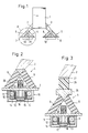
- Fig. 1 eine prinzipielle Motorabstützung über Keillager mit dem Entkopplungssystem,
- Fig. 2 einen Längsschnitt durch ein derartiges Keillager und durch das entsprechende, am Karossierieträger angeordnete Entkopplungssystem und
- Fig. 3 eine gleichartige Lageranordnung mit einer Zwischenmasse.
- Entsprechend der schematischen Darstellung in Fig. 1 wird ein Motor 1 an einem Ende beispielsweise über zwei schräg verlaufende Stützen 2 und 3 und zwei Keillager 4 und 5 mit Gummikörpern 6 aus hochdämpfendem Material auf zwei karosserieseitigen Trägern 7 und 8 abgestützt.
- Durch Motor- und Karosseriebewegungen eingeleitete Schwingungen größerer Amplitude im Bereich der Eigenfrequenzen von 5 bis 10 Hz werden von den Gummikörpern 6 durch Verwendung eines hochdämpfenden Gummis hinreichend gedämpft. Für hochfrequente Schwingungen von etwa 50 bis 300 Hz, also schon im akustischen Bereich, ist aber das Übertragungsverhalten eines solchen hochdämpfenden Gummis schlecht, so daß diese Schwingungen unzureichend gedämpft werden.
- Zur Dämmung dieser hochfrequenten Schwingungen ist daher ein elektrodynamisches Entkopplungssystem 10 vorgesehen, das auf der Karossierieseite des Lagers, beispielsweise auf der Unterseite der Träger 7 und 8, angeordnet ist und entsprechende Gegenschwingungen erzeugt.
- In Fig. 2 ist ein Schnitt im vergrößerten Maßstab durch den Bereich A aus Fig. 1 dargestellt. Dabei ist unterhalb des Trägers 7 das erfindungsgemäße Entkopplungssystem 10 angeordnet. Dieses besteht aus einem stationären Permanentmagneten 11 mit einem Weicheisenpfad 12, in dessen Spalt eine elektrische Spule 13 axial beweglich angeordnet ist, und zwar dadurch, daß sie an einem Ende an eine den Permanentmagneten 11 überspannende elastische Membran 14 angekoppelt ist. Die Spule 13 umschließt dabei eine topfförmige Tilgermasse 15, die ebenfalls mit der Membran 14 verbunden ist und auf die zusätzlich noch eine weitere Tilgermasse 16 aufgesetzt ist. Diese Tilgermassen 15 und 16 können dabei je nach Anforderung ein Gewicht von 5 bis 50 g aufweisen.
- Zur Ansteuerung dieses Entkopplungssystems 10 ist nun in unmittelbarer Nähe auf der Karosserieseite des Lagers, beispielsweise auf der Oberseite des Träger 7, ein Sensor 20 angeordnet, der an eine nicht näher dargestellte Stromversorgung angeschlossen und mit der Spule 13 des Entkopplungssystems 10 verbunden ist. Dieser Sensor 20 weist zweckmäßigerweise ein Filter auf, das nur hochfrequente Schwingungen von beispielsweise mehr als 50 Hz auf der karosserieseitigen Lagerseite erfaßt und ein zu diesen Schwingbewegungen proportionales elektrisches Signal abgibt. Bei geeigneter Entkopplung und elektrischer oder auch mechanischer Phasenverschiebung und nach entsprechender Verstärkung kann dieses Signal direkt auf die massenbeaufschlagte Spule 13 gegeben werden, und zwar so, daß die auftretenden Restbeschleunigungen und Schwingbewegungen automatisch minimiert werden.
- Dabei empfiehlt sich als Sensor 20 ein seismisches System, bestehend aus einer Masse 21 und einer federbeaufschlagten Spule 22 innerhalb eines Permanentmagneten 23, wobei die Spule ein ihrer Schwinggeschwindigkeit in erster Näherung proportionales elektrisches Signal abgibt.
- Für den vorliegenden Fall ist eine Phasenverschiebung von 180° zwischen der Schwingungserregung und der Tilgerspule 13 notwendig, um ein optimales Ergebnis zu erzielen. Diese Phasenverschiebung kann durch eine Umkehrschaltung oder eine Verzögerungsschaltung erreicht werden. Sie läßt sich aber auch auf mechanischem Wege sehr einfach dadurch bewirken, daß die Masse auf der Sensorspule im Sensor praktisch in Druckrichtung angebracht wird, während die Tilgermasse an der Spule des Entkopplungssystems nach unten gerichtet und somit in Zugrichtung angeordnet ist-oder aber entsprechend umgekehrt. Dadurch ergibt sich dann automatisch eine Signalverschiebung um 180` , die lediglich einer zwischengeschalteten Verstärkung bedarf, um das System zu optimieren.
- Fig. 3 zeigt nunmehr einen Schnitt durch ein entsprechendes Lager mit einer zusätzlichen Zwischenmasse 25. Dabei stützen sich die Motorstützen 2 bzw. 3 zunächst auf der Oberplatte 27 eines prismatischen Gummikörpers 26 aus hochdämpfenden Material ab. Zwischen diesem Gummikörper 26 und den Gummikörpern 6 des eiegentlichen Keillagers 4 ist nunmehr eine metallische Zwischenmasse 25 angeordnet, deren Masse etwa 100 bis 1000 g betragen kann.
- Der Vorteil einer solchen Zwischenmasse liegt darin, daß bei eingeleiteten Schwingungen jenseits des sich ergebenden Zwischenmassenpeaks, d.h. der Eigenfrequenz der Zwischenmasse, die Isolation bzw. Dämmung hochfrequenter Schwingungen sehr viel besser ist als bei einer Anordnung ohne Zwischenmasse; der Nachteil liegt allein in der schlechten Dämmung im Bereich der Eigenfrequenz dieser Zwischenmasse.
- Dieser Nachteil kann aber hierbei auch durch das Entkopplungssystem 10 - wie bei der Anordnung nach Fig. 2 beschrieben - behoben werden. Der elektrodynamische Tilger 15, 16 konterkariert dabei das Zwischenmassenpeak, so daß im hochfrequenten Bereich oberhalb der hochdämpfenden Wirkung des verwendeten Gummis für niedere Frequenzen etwa bis zu 20 Hz zunächst eine Dämmung von 40 dB/Dekade und in Bereichen jenseits des ursprünglichen Zwischenmassenpeaks eine Dämmung proportional 1/f4, d.h. von 80 dB/Dekade, erfolgt.
- Die wesentlichen Vorteile solcher Anordnungen bestehen darin, daß jetzt für das eigentliche Traglager ein hochdämpfender Gummi verwendet werden kann, um damit niederfrequente Schwingungen optimal zu dämpfen und daß für übertragene hochfrequente Schwingungen im akustischen Bereich ein einfach aufgebautes elektrodynamisches Entkopplungssystem vorgesehen ist, das eine dynamische Kraftentkopplung bewirkt. Dieses Entkopplungssystem macht dabei alle von der Karosserie herrührenden großhubigen Bewegungen mit, ohne daß es dabei die Fähigkeit einbüßt, hochfrequente Wechselkräfte zu erzeugen.
- Dabei wird bei einem Ausfall dieses Systems die eigentliche Abstützfunktion des Lagers in keiner Weise beeinträchtigt, so daß damit auch die Betriebssicherheit nicht vermindert wird.
Claims (11)
Applications Claiming Priority (2)
| Application Number | Priority Date | Filing Date | Title |
|---|---|---|---|
| DE4021035A DE4021035A1 (de) | 1990-07-02 | 1990-07-02 | Elastisches motorlager |
| DE4021035 | 1990-07-02 |
Publications (2)
| Publication Number | Publication Date |
|---|---|
| EP0464598A1 true EP0464598A1 (de) | 1992-01-08 |
| EP0464598B1 EP0464598B1 (de) | 1994-12-14 |
Family
ID=6409506
Family Applications (1)
| Application Number | Title | Priority Date | Filing Date |
|---|---|---|---|
| EP91110473A Expired - Lifetime EP0464598B1 (de) | 1990-07-02 | 1991-06-25 | Elastisches Motorlager |
Country Status (3)
| Country | Link |
|---|---|
| EP (1) | EP0464598B1 (de) |
| DE (2) | DE4021035A1 (de) |
| ES (1) | ES2066281T3 (de) |
Cited By (5)
| Publication number | Priority date | Publication date | Assignee | Title |
|---|---|---|---|---|
| EP0536760A1 (de) * | 1991-10-09 | 1993-04-14 | Honda Giken Kogyo Kabushiki Kaisha | Selbstausdehnendes Lager |
| FR2705416A1 (fr) * | 1993-05-19 | 1994-11-25 | Hutchinson | Installation antivibratoire à vibrateurs magnétiques de support actif. |
| EP0821180A3 (de) * | 1996-07-26 | 1999-03-17 | Tokai Rubber Industries, Ltd. | Schwingungsdämpfer mit Schwingungsgenerator mit oszillierenden Kräften für relative Bewegung von ersten und zweiten Gewichtsgruppen |
| EP1653117A1 (de) * | 2004-10-28 | 2006-05-03 | Hutchinson | Verfahren zum Auswuchten eines Motors und Vorrichtung zum Durchführen des Verfahrens |
| US9669676B2 (en) | 2013-09-25 | 2017-06-06 | Audi Ag | Method for operating an electromagnetic actuator in a motor vehicle |
Families Citing this family (5)
| Publication number | Priority date | Publication date | Assignee | Title |
|---|---|---|---|---|
| JP3039077B2 (ja) | 1991-11-29 | 2000-05-08 | 東海ゴム工業株式会社 | 流体封入式防振装置 |
| DE4141637A1 (de) * | 1991-12-17 | 1993-06-24 | Metzeler Gimetall Ag | Aktives, elastisches lager |
| DE19940678A1 (de) | 1998-08-28 | 2000-05-25 | Toyoda Automatic Loom Works | Montagestruktur für einen Sensor in einem Industriefahrzeug und Industriefahrzeug |
| DE102004043135B3 (de) * | 2004-09-07 | 2006-04-27 | Carl Freudenberg Kg | Aktiver Schwingungstilger |
| DE102009021466B4 (de) * | 2009-05-15 | 2012-03-22 | Kuhnke Automotive Gmbh & Co. Kg | Elektrischer Schwingungserreger |
Citations (7)
| Publication number | Priority date | Publication date | Assignee | Title |
|---|---|---|---|---|
| EP0119626A2 (de) * | 1983-03-22 | 1984-09-26 | Nissan Motor Co., Ltd. | Motorlager |
| DE3314335A1 (de) * | 1983-04-20 | 1984-10-31 | Tillmann 6108 Weiterstadt Freudenberg | Motorlager |
| EP0163162A2 (de) * | 1984-05-24 | 1985-12-04 | METZELER Gesellschaft mit beschränkter Haftung | Zweikammer-Motorlager mit hydraulischer Dämpfung |
| DE3431117A1 (de) * | 1984-08-24 | 1986-03-06 | Adam Opel AG, 6090 Rüsselsheim | Elastisches lager und lagerung eines motors |
| EP0290181A2 (de) * | 1987-05-08 | 1988-11-09 | BTR plc | Fahrzeugmotoraufhängungssysteme |
| GB2205921A (en) * | 1987-06-03 | 1988-12-21 | Hitachi Ltd | A vibration damping apparatus |
| FR2642492A1 (fr) * | 1989-01-28 | 1990-08-03 | Continental Ag | Support elastique, notamment support pour moteur de vehicule automobile |
Family Cites Families (2)
| Publication number | Priority date | Publication date | Assignee | Title |
|---|---|---|---|---|
| DE2807160A1 (de) * | 1978-02-20 | 1979-08-30 | Continental Gummi Werke Ag | Lagerelement zum elastischen unterstuetzen insbesondere von motoren in kraftfahrzeugen |
| DE3630360A1 (de) * | 1986-09-05 | 1988-03-17 | Metzeler Kautschuk | Lager zur elastischen abstuetzung von maschinen |
-
1990
- 1990-07-02 DE DE4021035A patent/DE4021035A1/de active Granted
-
1991
- 1991-06-25 ES ES91110473T patent/ES2066281T3/es not_active Expired - Lifetime
- 1991-06-25 EP EP91110473A patent/EP0464598B1/de not_active Expired - Lifetime
- 1991-06-25 DE DE59103859T patent/DE59103859D1/de not_active Expired - Fee Related
Patent Citations (7)
| Publication number | Priority date | Publication date | Assignee | Title |
|---|---|---|---|---|
| EP0119626A2 (de) * | 1983-03-22 | 1984-09-26 | Nissan Motor Co., Ltd. | Motorlager |
| DE3314335A1 (de) * | 1983-04-20 | 1984-10-31 | Tillmann 6108 Weiterstadt Freudenberg | Motorlager |
| EP0163162A2 (de) * | 1984-05-24 | 1985-12-04 | METZELER Gesellschaft mit beschränkter Haftung | Zweikammer-Motorlager mit hydraulischer Dämpfung |
| DE3431117A1 (de) * | 1984-08-24 | 1986-03-06 | Adam Opel AG, 6090 Rüsselsheim | Elastisches lager und lagerung eines motors |
| EP0290181A2 (de) * | 1987-05-08 | 1988-11-09 | BTR plc | Fahrzeugmotoraufhängungssysteme |
| GB2205921A (en) * | 1987-06-03 | 1988-12-21 | Hitachi Ltd | A vibration damping apparatus |
| FR2642492A1 (fr) * | 1989-01-28 | 1990-08-03 | Continental Ag | Support elastique, notamment support pour moteur de vehicule automobile |
Non-Patent Citations (1)
| Title |
|---|
| PATENT ABSTRACTS OF JAPAN, Band 12, Nr. 475 (M-774)[3322], 13. Dezember 1988; & JP-A-63 195 443 (EIJI ADACHI) 12-08-1988 * |
Cited By (9)
| Publication number | Priority date | Publication date | Assignee | Title |
|---|---|---|---|---|
| EP0536760A1 (de) * | 1991-10-09 | 1993-04-14 | Honda Giken Kogyo Kabushiki Kaisha | Selbstausdehnendes Lager |
| US5344128A (en) * | 1991-10-09 | 1994-09-06 | Honda Giken Kogyo Kabushiki Kaisha | Self-expanding mount |
| FR2705416A1 (fr) * | 1993-05-19 | 1994-11-25 | Hutchinson | Installation antivibratoire à vibrateurs magnétiques de support actif. |
| EP0821180A3 (de) * | 1996-07-26 | 1999-03-17 | Tokai Rubber Industries, Ltd. | Schwingungsdämpfer mit Schwingungsgenerator mit oszillierenden Kräften für relative Bewegung von ersten und zweiten Gewichtsgruppen |
| US5967269A (en) * | 1996-07-26 | 1999-10-19 | Tokai Rubber Industries, Ltd. | Vibration damper incorporating oscillating means for generating oscillating force for relative displacement of first and second mass assemblies |
| EP1653117A1 (de) * | 2004-10-28 | 2006-05-03 | Hutchinson | Verfahren zum Auswuchten eines Motors und Vorrichtung zum Durchführen des Verfahrens |
| FR2877414A1 (fr) * | 2004-10-28 | 2006-05-05 | Hutchinson Sa | Procede d'equilibrage pour moteur et dispositif pour la mise en oeuvre de ce procede |
| JP2006125636A (ja) * | 2004-10-28 | 2006-05-18 | Hutchinson Sa | エンジンのためのバランシング法およびバランシング法を実装する装置 |
| US9669676B2 (en) | 2013-09-25 | 2017-06-06 | Audi Ag | Method for operating an electromagnetic actuator in a motor vehicle |
Also Published As
| Publication number | Publication date |
|---|---|
| DE59103859D1 (de) | 1995-01-26 |
| DE4021035C2 (de) | 1992-06-04 |
| DE4021035A1 (de) | 1992-01-16 |
| ES2066281T3 (es) | 1995-03-01 |
| EP0464598B1 (de) | 1994-12-14 |
Similar Documents
| Publication | Publication Date | Title |
|---|---|---|
| DE3314335C2 (de) | ||
| EP0580272B1 (de) | Schwingungsdämpfer | |
| DE3419437C2 (de) | ||
| EP2673531B1 (de) | Schwingungsfreie lagerung eines objekts an einer struktur | |
| DE19739877C2 (de) | Mechanischer Resonator mit variabler Resonanzfrequenz | |
| DE3523973C2 (de) | ||
| DE19621700C2 (de) | Aktiver Schwingungsminderer | |
| DE2603688C3 (de) | Anordnung zum Schwingungsausgleich | |
| EP0547469B1 (de) | Aktives, elastisches Lager | |
| DE3139915A1 (de) | Luftgedaempftes gummilager | |
| EP0209883A2 (de) | Zweikammer-Motorlager mit hydraulischer Dämpfung | |
| EP0134749B1 (de) | Flexible gedämpfte Wellenlageranordnung, insbesondere für elektrische Maschinen | |
| EP0110197A1 (de) | Zweikammer-Motorlager mit hydraulischer Dämpfung | |
| DE60028654T2 (de) | Resonante Vorrichtung wie Schläger oder Klopfer | |
| EP0464598A1 (de) | Elastisches Motorlager | |
| DE3874443T2 (de) | Verfahren zur steuerung eines schwingungsdaempfers. | |
| DE2821617C2 (de) | Mikrophon mit einer Anordnung zur Unterdrückung von Körperschall | |
| DE3920346C2 (de) | ||
| EP0464597B1 (de) | Aktives hydraulisch dämpfendes Motorlager | |
| EP0271848B1 (de) | Aktives, hydraulisch dämpfendes Motorlager | |
| DE60034627T2 (de) | Resonanzvorrichtung wie Schläger oder Krafterzeuger | |
| DE4021038C2 (de) | ||
| DE930731C (de) | Befestigung moeglichst erschuetterungsfrei anzubringender Hilfsgeraete auf Kraftfahrzeugen, insbesondere von elektrischen Batterien auf Ackerschleppern | |
| DE3501111C2 (de) | Motorlager | |
| DE3152751A1 (de) | Lager zur schwingungsisolierenden abstuetzung bzw. aufhaengung des motors eines kraftfahrzeuges an dessen fahrgestell |
Legal Events
| Date | Code | Title | Description |
|---|---|---|---|
| PUAI | Public reference made under article 153(3) epc to a published international application that has entered the european phase |
Free format text: ORIGINAL CODE: 0009012 |
|
| AK | Designated contracting states |
Kind code of ref document: A1 Designated state(s): DE ES FR GB IT SE |
|
| 17P | Request for examination filed |
Effective date: 19920227 |
|
| 17Q | First examination report despatched |
Effective date: 19930714 |
|
| GRAA | (expected) grant |
Free format text: ORIGINAL CODE: 0009210 |
|
| AK | Designated contracting states |
Kind code of ref document: B1 Designated state(s): DE ES FR GB IT SE |
|
| ITF | It: translation for a ep patent filed | ||
| REF | Corresponds to: |
Ref document number: 59103859 Country of ref document: DE Date of ref document: 19950126 |
|
| REG | Reference to a national code |
Ref country code: ES Ref legal event code: FG2A Ref document number: 2066281 Country of ref document: ES Kind code of ref document: T3 |
|
| GBT | Gb: translation of ep patent filed (gb section 77(6)(a)/1977) |
Effective date: 19950208 |
|
| ET | Fr: translation filed | ||
| PLBE | No opposition filed within time limit |
Free format text: ORIGINAL CODE: 0009261 |
|
| STAA | Information on the status of an ep patent application or granted ep patent |
Free format text: STATUS: NO OPPOSITION FILED WITHIN TIME LIMIT |
|
| 26N | No opposition filed | ||
| PGFP | Annual fee paid to national office [announced via postgrant information from national office to epo] |
Ref country code: GB Payment date: 19970707 Year of fee payment: 7 |
|
| PGFP | Annual fee paid to national office [announced via postgrant information from national office to epo] |
Ref country code: FR Payment date: 19970717 Year of fee payment: 7 |
|
| PGFP | Annual fee paid to national office [announced via postgrant information from national office to epo] |
Ref country code: SE Payment date: 19970722 Year of fee payment: 7 |
|
| PGFP | Annual fee paid to national office [announced via postgrant information from national office to epo] |
Ref country code: ES Payment date: 19970730 Year of fee payment: 7 |
|
| PG25 | Lapsed in a contracting state [announced via postgrant information from national office to epo] |
Ref country code: GB Free format text: LAPSE BECAUSE OF NON-PAYMENT OF DUE FEES Effective date: 19980625 |
|
| PG25 | Lapsed in a contracting state [announced via postgrant information from national office to epo] |
Ref country code: SE Free format text: LAPSE BECAUSE OF NON-PAYMENT OF DUE FEES Effective date: 19980626 Ref country code: ES Free format text: LAPSE BECAUSE OF NON-PAYMENT OF DUE FEES Effective date: 19980626 |
|
| GBPC | Gb: european patent ceased through non-payment of renewal fee |
Effective date: 19980625 |
|
| PG25 | Lapsed in a contracting state [announced via postgrant information from national office to epo] |
Ref country code: FR Free format text: LAPSE BECAUSE OF NON-PAYMENT OF DUE FEES Effective date: 19990226 |
|
| EUG | Se: european patent has lapsed |
Ref document number: 91110473.5 |
|
| REG | Reference to a national code |
Ref country code: FR Ref legal event code: ST |
|
| REG | Reference to a national code |
Ref country code: ES Ref legal event code: FD2A Effective date: 20000403 |
|
| PG25 | Lapsed in a contracting state [announced via postgrant information from national office to epo] |
Ref country code: IT Free format text: LAPSE BECAUSE OF NON-PAYMENT OF DUE FEES;WARNING: LAPSES OF ITALIAN PATENTS WITH EFFECTIVE DATE BEFORE 2007 MAY HAVE OCCURRED AT ANY TIME BEFORE 2007. THE CORRECT EFFECTIVE DATE MAY BE DIFFERENT FROM THE ONE RECORDED. Effective date: 20050625 |
|
| PGFP | Annual fee paid to national office [announced via postgrant information from national office to epo] |
Ref country code: DE Payment date: 20080715 Year of fee payment: 18 |
|
| PG25 | Lapsed in a contracting state [announced via postgrant information from national office to epo] |
Ref country code: DE Free format text: LAPSE BECAUSE OF NON-PAYMENT OF DUE FEES Effective date: 20100101 |