EP0464651A1 - Presse pour grandes balles - Google Patents
Presse pour grandes balles Download PDFInfo
- Publication number
- EP0464651A1 EP0464651A1 EP91110596A EP91110596A EP0464651A1 EP 0464651 A1 EP0464651 A1 EP 0464651A1 EP 91110596 A EP91110596 A EP 91110596A EP 91110596 A EP91110596 A EP 91110596A EP 0464651 A1 EP0464651 A1 EP 0464651A1
- Authority
- EP
- European Patent Office
- Prior art keywords
- yarn
- bale
- supply
- big
- channel
- Prior art date
- Legal status (The legal status is an assumption and is not a legal conclusion. Google has not performed a legal analysis and makes no representation as to the accuracy of the status listed.)
- Granted
Links
Images



Classifications
-
- A—HUMAN NECESSITIES
- A01—AGRICULTURE; FORESTRY; ANIMAL HUSBANDRY; HUNTING; TRAPPING; FISHING
- A01F—PROCESSING OF HARVESTED PRODUCE; HAY OR STRAW PRESSES; DEVICES FOR STORING AGRICULTURAL OR HORTICULTURAL PRODUCE
- A01F15/00—Baling presses for straw, hay or the like
- A01F15/08—Details
- A01F15/14—Tying devices specially adapted for baling presses
Definitions
- the invention relates to a large baler of the type specified in the preamble of claim 1 and in the preamble of the independent claim 4.
- Each large bale is tied into several parallel twine loops.
- Each twine loop is formed by holding the twine between the twine supply and the feed needle on one side of the baling channel and the knotting device on the other side of the baling channel before the nascent large bale is pushed through the baling channel and the yarn is taken off and on follows. Due to the friction on the surfaces of the large bale, the tension increases sharply in the twine section held by the knotting device, so that the knotting device is high, e.g. with 1500 N, is loaded.
- a lever with a lower transverse arm which is pivotably mounted in front of and above the knotting device is provided in the yarn-forming device.
- the lever is pivoted away from the knotting device to form the thread supply.
- the feed needle is moved over the cross arm, through the knife lever and over the tying hook of the tying device.
- Both yarn sections defined in the yarn holder of the knotting device lie on the cross arm.
- the knife lever remains inoperative.
- the cross arm is swiveled up to under the knot hook to relax the thread section. Only then can the knife lever support and guide the thread.
- the danger determines that until the knife lever engages, the further yarn section, which is gradually tensioned during the bale movements and relaxes suddenly when the cross arm is pivoted, slips sideways.
- This danger cannot be reliably excluded by the additional guide fingers attached to the lower arm.
- the yarn stocking device interferes with the proper cooperation between the feed needle and the knotting device, which is important for proper knots.
- the feed needle cannot work optimally with the knot hook because of the cross arm.
- the invention has for its object to provide a large baler of the type mentioned, which is characterized by a simple, yet reliable and space-saving device for forming a yarn supply.
- the deflection element uses the baling channel or part of the space in the baling channel that is occupied by the large bale to form the supply. This results in a desirably small space requirement for the yarn supply formation.
- the yarn tension that can be reduced when the deflection element yields leads to a constant knot quality even with large bales and relatively strong yarn.
- the quota due to ends of bad knots pulled out of the thread holder is noticeably reduced.
- the release of the thread supply takes place depending on the actuation of the knotting device or depending on a preselected thread tension value.
- the device can be retrofitted into large balers that have already been used without any noteworthy modifications, in order to improve the knot quality and reduce wear. This effect already occurs when approx. 1/3 of the otherwise occurring yarn tension is reduced by the yarn supply.
- the knotting device has a double function. It temporarily forms the yarn supply by pulling the yarn against the pressing direction before knotting or deflecting it from the yarn path present when knotting. The thread supply is released to form the knot.
- the device takes up little space.
- the knife lever supports and guides the yarn permanently so that it does not slip sideways.
- the groove shape channel and the depth of the groove shape channel and the depth of the groove shape channel are used for the movement stroke of the deflecting element, in order to form the largest possible yarn supply, the yarn being particularly advantageously supported by the knife lever against lateral evasion and under the unavoidably rough working conditions to be led.
- the knotting device pulls the yarn before the knot formation by a certain amount against the pressing direction. Only immediately before the knot is formed is the knotting device pushed back into the knot formation in order to release the thread supply and only then to form the knot. The yarn is not significantly deflected, so that this embodiment takes up little space.
- the knotting device or at least its twine holder executes a pivoting movement caused by the actuator in order to form the twine supply before the knot is formed.
- the embodiment according to claim 7 is advantageous because the knotting device is stably supported in the respective end position. Individual adaptation to different conditions, e.g. Different bale lengths are possible by adjusting the stops for the range of motion of the knotting device.
- the yarn supply is temporarily produced with a zigzag-shaped deflection of the yarn to save space.
- This embodiment can be advantageous if the thread supply formed by the deflecting element dipping into the surface of the large bale or by the moving knotting device should not be sufficient to sufficiently relax the yarn. Very little space is required for the zigzag-shaped deflection and the stops as well as the slide.
- the embodiment according to claim 9 is particularly expedient because a relatively large supply of yarn is formed in the smallest space when the stops and the slide move in opposite directions.
- a large baler P which can be pulled and driven by a tractor (not shown), produces cuboidal large bales G from cut forage E, which for example have dimensions of 0.60 / 1.20 / 1.20-2.80 m (H / W / L) to have.
- the press P has a receiving part A with a pick-up roller S and lateral shaping screws T.
- a wing roller R conveys the crop from below into a baling channel K, in which a baling piston Z compresses in cycles.
- Each large bale G is divided into several, e.g. five, twine loops D knotted in before it is ejected in reverse.
- a supply of a yarn B is arranged in the chassis, from which the yarn runs through the tip of a curved feed needle N and then upwards across the press channel K to a knotting device U, which has a holder, not shown, for the free yarn end contains.
- a separate supply, a feed needle R and a knotting device U are provided for each yarn loop D.
- the knotting devices Ü are located in an upper part 1 of the large baler P.
- the press channel K is delimited at the top and bottom by walls 2, 3.
- the lower wall 3 is extended at 4 and connected to a placement device 5 for the finished and knotted large bales G.
- the feed needles are motionally coupled via a link 6 to the knotting devices Ü, which are seated on a drive shaft 7 in the upper part 1 and each contain a knotting hook 8.
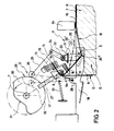
- knotting devices Ü devices V which can be removed from FIGS. 2 to 4 are provided in detail for temporarily forming a yarn supply in the respective upper, further yarn section 10 of each yarn loop D.
- the further yarn section 10 extends from the edge of the large bale G lying in the pressing direction to the knotting device Ü.
- the yarn part extending along the front end face in the pressing direction is indicated by 11.
- the part of the loop D which runs along the lower wall 3 of the press channel from the lower edge of the large bale G lying in the pressing direction to the feed needle N or to the supply is designated by 12.
- the yarn loop D is formed by pushing the nascent bale forward, taking with it the yarn that runs out of the supply. After completion of the pressing process and while the piston Z is retracted, the feed needle N transfers a further part 9 (FIG. 2) of the yarn to the knotting device Ü, the holder 14 of which holds the yarn before the knotting hook 8 forms a knot which, after cutting off the yarn end is thrown off. The new yarn end is held in the holder again.
- the knotting device U is e.g. a "Deering knotting device" of known design.
- the rear, upper end of the large bale G in the baling channel K can be seen schematically in FIG.
- the free end, designated 13, of the further yarn section 10 is fixed in the holder 14 together with the free end of the yarn section 9.
- a yarn part 9a hangs down from the knotting device Ü across the baling channel.
- a knife 15 is held on a knife lever 16, which is designed like a fork and forms a support and guide for the further yarn section 10.
- the knotting hook 8 is fastened to an inclined shaft 17 which can be coupled to the drive shaft 7 via a drive (not shown) in order to form and knot during a 360 ° rotation.
- the number of twine loops D corresponding to the number of groove-shaped channels 18, are provided, which engage in the surface of the large bale G and form grooves for the twine loops D.
- the channel 18 is open at the bottom and equipped with an angled deflector 19 on the inside.
- the device V has a deflection element E in the form of a cross pin 20 which is attached to an arm 21 of a shaft 22 which is mounted in a stationary manner in a bearing 23.
- a rocker arm 24 is also attached so as to protrude upward, which is coupled via a link 25 to a cam follower 26 which is located at the free end of a lever 27.
- the lever 27 is pivotally mounted in a bearing 28 and is acted upon counterclockwise by a spring 33 in FIG.
- the cam follower 26 is pressed against a cam track 29 of a cam disk 30 which is fastened on the drive shaft 7.
- the cam track 29 consists of two sections 31, 32, the section 31 corresponding to the relief position 20 1 of the deflecting element E and the section 32 corresponding to a deflecting position 20 ′′ of the deflecting element E.
- the individual components of the device V are shown in the deflected position in solid lines, while dash-dotted lines indicate which positions the individual components occupy in the relief position of the deflection element E.
- the deflecting element E remains in the deflecting position (20 ").
- the cam follower 26 comes from the cam track part 32 onto the cam track part 31, so that the deflecting element E is moved into the relief position 20 1.
- the further yarn section assumes the position indicated by dash-dotted lines and is at least partially relaxed.
- the knotting hook 8 forms a knot, both free yarn ends being held in the holder 14 The knot is pushed off the knotting hook 8, the holder 14 being moved so that the knife 15 separates the yarn parts 9 and 9.
- the knot is tightened by the tension in the yarn and falls onto the large bale G, which is then pushed out
- the new, free yarn end of part 9a remains in the holder 14.
- the cam follower 26 succeeded gt again on the cam track part 32. Meanwhile, a new large bale G is started, which again forms a yarn loop D.
- the further yarn section 10 is deflected again. Then the processes described above run again.
- a deflection element E is provided for each knotting device Ü. All deflection elements can be mounted on the common shaft 22 which is driven on one side of the press P in the manner shown or in the middle between the knotting devices Ü.
- the knotting device U serves as the device V for temporarily forming a thread supply in the further yarn section 10.
- the knotting hook 8, together with the knife lever 16 and the holder 14, can be pivoted to a limited extent about the drive shaft 7 in such a way that in the position shown a yarn supply is formed in the yarn section 10.
- a lever 34 is used, on which an actuating cylinder 35 is matured, with which the lever 34 can be pivoted back and forth between two stops 36 and 37.
- the device V is of a different type. It can be seen how the knife lever 16 engages under the knotting hook 8.
- the device V consists of two spaced stops 40, 41, between which the deflection element E, which is designed as a slide 42, can be inserted transversely to the yarn until the yarn is deflected in a zigzag shape, specifically here in the horizontal direction.
- the slide 42 is withdrawn and the thread supply is made available.
- the slide 42 is brought into the position shown.
- the stops 40, 41 can be stationary. However, it is also conceivable to move the stops 40, 41 in the opposite direction to the slide 42 and simultaneously with the latter in order to form the largest possible yarn supply.
- the embodiment according to FIG. 2 is suitable for retrofitting large balers that have already been in operation, because previously used components can continue to be used without any significant modifications. It is only necessary to mount a shaft 22 common to all deflection elements E at the knotting devices Ü, to mount the cam disk 30 at a suitable location on the drive shaft 7 and to install the steering connection 24, 25, 26, 27, 28 with the springs 33.
Landscapes
- Life Sciences & Earth Sciences (AREA)
- Environmental Sciences (AREA)
- Binders And Loading Units For Sheaves (AREA)
- Basic Packing Technique (AREA)
Applications Claiming Priority (2)
| Application Number | Priority Date | Filing Date | Title |
|---|---|---|---|
| DE4020497 | 1990-06-27 | ||
| DE4020497A DE4020497A1 (de) | 1990-06-27 | 1990-06-27 | Grossballenpresse |
Publications (2)
| Publication Number | Publication Date |
|---|---|
| EP0464651A1 true EP0464651A1 (fr) | 1992-01-08 |
| EP0464651B1 EP0464651B1 (fr) | 1994-05-18 |
Family
ID=6409201
Family Applications (1)
| Application Number | Title | Priority Date | Filing Date |
|---|---|---|---|
| EP91110596A Expired - Lifetime EP0464651B1 (fr) | 1990-06-27 | 1991-06-26 | Presse pour grandes balles |
Country Status (2)
| Country | Link |
|---|---|
| EP (1) | EP0464651B1 (fr) |
| DE (2) | DE4020497A1 (fr) |
Cited By (2)
| Publication number | Priority date | Publication date | Assignee | Title |
|---|---|---|---|---|
| CN116762574A (zh) * | 2023-08-25 | 2023-09-19 | 黑龙江省农业科学院大庆分院 | 一种甜瓜收秧打捆机 |
| EP4721552A1 (fr) * | 2024-10-01 | 2026-04-08 | Maschinenfabrik Bernard Krone GmbH & Co. KG | Presse à balles |
Families Citing this family (2)
| Publication number | Priority date | Publication date | Assignee | Title |
|---|---|---|---|---|
| DE4201086C2 (de) * | 1992-01-17 | 1993-12-09 | Siegfried Sommerfeld | Verfahren und Vorrichtung zum automatischen Umschnüren von Ballen mit mindestens einem Kunststoffband |
| US7954633B2 (en) * | 2003-05-08 | 2011-06-07 | Deere & Company | Large round bale wrapped in protective wrapping and method for producing such a wrapped bale |
Citations (5)
| Publication number | Priority date | Publication date | Assignee | Title |
|---|---|---|---|---|
| US3214205A (en) * | 1963-09-23 | 1965-10-26 | Int Harvester Co | Cord holder for knotter |
| GB2028220A (en) * | 1978-08-11 | 1980-03-05 | Fortschritt Veb K | Baling apparatus |
| EP0084680A1 (fr) * | 1982-01-25 | 1983-08-03 | Lindemann Maschinenfabrik GmbH | Appareil pour lier des balles dans une presse à balles |
| EP0199615A1 (fr) * | 1985-04-03 | 1986-10-29 | Rivierre Casalis | Presse à balles parallélépipédiques avec dispositif de réduction et de compensation de la tension du fil de liage |
| US4765235A (en) * | 1987-04-15 | 1988-08-23 | Hay & Forage Industries | Monitoring system for detecting malfunction of knotting mechanism on a crop baler |
Family Cites Families (3)
| Publication number | Priority date | Publication date | Assignee | Title |
|---|---|---|---|---|
| US4088068A (en) * | 1976-08-25 | 1978-05-09 | Hesston Corporation | Slackening mechanism for bale tier |
| DK129283A (da) * | 1983-03-22 | 1984-09-23 | Weidemann & Soenner L P | Fremgangsmaade til nedsaettelse af garnspaendingen i en halmballepresser og kompensationsapparat til fastgoerelse af en halmballepresser til udoevelse af fremgangsmaaden |
| DD282837A5 (de) * | 1989-05-08 | 1990-09-26 | Mechanisierung & Energie | Bindevorrichtung fuer ballenpressen |
-
1990
- 1990-06-27 DE DE4020497A patent/DE4020497A1/de active Granted
-
1991
- 1991-06-26 EP EP91110596A patent/EP0464651B1/fr not_active Expired - Lifetime
- 1991-06-26 DE DE59101645T patent/DE59101645D1/de not_active Expired - Fee Related
Patent Citations (5)
| Publication number | Priority date | Publication date | Assignee | Title |
|---|---|---|---|---|
| US3214205A (en) * | 1963-09-23 | 1965-10-26 | Int Harvester Co | Cord holder for knotter |
| GB2028220A (en) * | 1978-08-11 | 1980-03-05 | Fortschritt Veb K | Baling apparatus |
| EP0084680A1 (fr) * | 1982-01-25 | 1983-08-03 | Lindemann Maschinenfabrik GmbH | Appareil pour lier des balles dans une presse à balles |
| EP0199615A1 (fr) * | 1985-04-03 | 1986-10-29 | Rivierre Casalis | Presse à balles parallélépipédiques avec dispositif de réduction et de compensation de la tension du fil de liage |
| US4765235A (en) * | 1987-04-15 | 1988-08-23 | Hay & Forage Industries | Monitoring system for detecting malfunction of knotting mechanism on a crop baler |
Cited By (3)
| Publication number | Priority date | Publication date | Assignee | Title |
|---|---|---|---|---|
| CN116762574A (zh) * | 2023-08-25 | 2023-09-19 | 黑龙江省农业科学院大庆分院 | 一种甜瓜收秧打捆机 |
| CN116762574B (zh) * | 2023-08-25 | 2023-10-31 | 黑龙江省农业科学院大庆分院 | 一种甜瓜收秧打捆机 |
| EP4721552A1 (fr) * | 2024-10-01 | 2026-04-08 | Maschinenfabrik Bernard Krone GmbH & Co. KG | Presse à balles |
Also Published As
| Publication number | Publication date |
|---|---|
| DE59101645D1 (de) | 1994-06-23 |
| DE4020497C2 (fr) | 1993-01-07 |
| DE4020497A1 (de) | 1992-01-09 |
| EP0464651B1 (fr) | 1994-05-18 |
Similar Documents
| Publication | Publication Date | Title |
|---|---|---|
| EP0159049B1 (fr) | Dispositif de liage pour balles cylindriques | |
| EP0157898B1 (fr) | Mécanisme de liage pour presses à balles rondes | |
| EP0084680B1 (fr) | Appareil pour lier des balles dans une presse à balles | |
| DE2826904C2 (fr) | ||
| DE3150614C2 (de) | Automatische Umschnürungsvorrichtung an landwirtschaftlichen Rollballenpressen | |
| DE102020120445B4 (de) | Garnknoter und Ballenpresse mit einem Garnknoter | |
| DE2801309A1 (de) | Verfahren und vorrichtung zum binden von rundballen aus landwirtschaftlichem erntegut | |
| DE102020120447B4 (de) | Knoterhaken für einen Garnknoter | |
| DE3445060C2 (fr) | ||
| EP0535532A2 (fr) | Procédé et dispositif pour lier des balles de récolte | |
| DE3436883A1 (de) | Verfahren zum herstellen von rechteckigen grossballen aus geschnittenem halmgut und grossballenpresse | |
| DE4020497C2 (fr) | ||
| DE3024101A1 (de) | Bindegarnbetaetigter abschneider fuer eine rollballen-formvorrichtung | |
| DE3822553A1 (de) | Verfahren und vorrichtung zum umschnueren von rundballen aus landwirtschaftlichem erntegut | |
| EP0095681B1 (fr) | Presse à balles rondes | |
| DE4031695C2 (de) | Vorrichtung zur Erhöhung der Bindesicherheit und -qualität an Großballenpressen | |
| EP1234495B1 (fr) | Presse-botteleuse avec dispositif de liage | |
| DE3125172C2 (fr) | ||
| DE102019115620B4 (de) | Ballenpresse für landwirtschaftliches Pressgut | |
| DE102024107851B3 (de) | Garnknoter zum Erzeugen eines Knotens in Garnsträngen | |
| DE102024131686A1 (de) | Knotereinrichtung | |
| DE3787108T2 (de) | Rundballenpresse. | |
| DE102024131696A1 (de) | Knotereinrichtung | |
| DE2743727B2 (de) | Vorrichtung zum Abschneiden des Nadel- und Spulenfadens an einer automatischen Nähmaschine | |
| DE250806C (fr) |
Legal Events
| Date | Code | Title | Description |
|---|---|---|---|
| PUAI | Public reference made under article 153(3) epc to a published international application that has entered the european phase |
Free format text: ORIGINAL CODE: 0009012 |
|
| AK | Designated contracting states |
Kind code of ref document: A1 Designated state(s): DE DK FR GB NL |
|
| 17P | Request for examination filed |
Effective date: 19911121 |
|
| 17Q | First examination report despatched |
Effective date: 19921103 |
|
| GRAA | (expected) grant |
Free format text: ORIGINAL CODE: 0009210 |
|
| AK | Designated contracting states |
Kind code of ref document: B1 Designated state(s): DE DK FR GB NL |
|
| PG25 | Lapsed in a contracting state [announced via postgrant information from national office to epo] |
Ref country code: DK Effective date: 19940518 |
|
| GBT | Gb: translation of ep patent filed (gb section 77(6)(a)/1977) |
Effective date: 19940518 |
|
| REF | Corresponds to: |
Ref document number: 59101645 Country of ref document: DE Date of ref document: 19940623 |
|
| ET | Fr: translation filed | ||
| PLBE | No opposition filed within time limit |
Free format text: ORIGINAL CODE: 0009261 |
|
| 26N | No opposition filed | ||
| PGFP | Annual fee paid to national office [announced via postgrant information from national office to epo] |
Ref country code: GB Payment date: 19960520 Year of fee payment: 6 |
|
| PGFP | Annual fee paid to national office [announced via postgrant information from national office to epo] |
Ref country code: FR Payment date: 19960604 Year of fee payment: 6 |
|
| PGFP | Annual fee paid to national office [announced via postgrant information from national office to epo] |
Ref country code: NL Payment date: 19960618 Year of fee payment: 6 |
|
| PGFP | Annual fee paid to national office [announced via postgrant information from national office to epo] |
Ref country code: DE Payment date: 19960731 Year of fee payment: 6 |
|
| PG25 | Lapsed in a contracting state [announced via postgrant information from national office to epo] |
Ref country code: GB Free format text: LAPSE BECAUSE OF NON-PAYMENT OF DUE FEES Effective date: 19970626 |
|
| PG25 | Lapsed in a contracting state [announced via postgrant information from national office to epo] |
Ref country code: NL Effective date: 19980101 |
|
| GBPC | Gb: european patent ceased through non-payment of renewal fee |
Effective date: 19970626 |
|
| PG25 | Lapsed in a contracting state [announced via postgrant information from national office to epo] |
Ref country code: FR Free format text: LAPSE BECAUSE OF NON-PAYMENT OF DUE FEES Effective date: 19980227 |
|
| NLV4 | Nl: lapsed or anulled due to non-payment of the annual fee |
Effective date: 19980101 |
|
| PG25 | Lapsed in a contracting state [announced via postgrant information from national office to epo] |
Ref country code: DE Free format text: LAPSE BECAUSE OF NON-PAYMENT OF DUE FEES Effective date: 19980303 |
|
| REG | Reference to a national code |
Ref country code: FR Ref legal event code: ST |
|
| REG | Reference to a national code |
Ref country code: FR Ref legal event code: ST |