EP0464683A1 - Compresseur à fluide - Google Patents
Compresseur à fluide Download PDFInfo
- Publication number
- EP0464683A1 EP0464683A1 EP91110680A EP91110680A EP0464683A1 EP 0464683 A1 EP0464683 A1 EP 0464683A1 EP 91110680 A EP91110680 A EP 91110680A EP 91110680 A EP91110680 A EP 91110680A EP 0464683 A1 EP0464683 A1 EP 0464683A1
- Authority
- EP
- European Patent Office
- Prior art keywords
- cylinder
- rotary member
- fluid
- closed case
- inlet
- Prior art date
- Legal status (The legal status is an assumption and is not a legal conclusion. Google has not performed a legal analysis and makes no representation as to the accuracy of the status listed.)
- Withdrawn
Links
- 239000012530 fluid Substances 0.000 title claims abstract description 29
- 230000006835 compression Effects 0.000 claims abstract description 9
- 238000007906 compression Methods 0.000 claims abstract description 9
- 238000007599 discharging Methods 0.000 claims abstract description 4
- 239000003507 refrigerant Substances 0.000 description 8
- 230000008878 coupling Effects 0.000 description 4
- 238000010168 coupling process Methods 0.000 description 4
- 238000005859 coupling reaction Methods 0.000 description 4
- 238000005057 refrigeration Methods 0.000 description 3
- 238000005452 bending Methods 0.000 description 2
- 238000000034 method Methods 0.000 description 2
- 238000004891 communication Methods 0.000 description 1
- 238000010276 construction Methods 0.000 description 1
- 238000010586 diagram Methods 0.000 description 1
- 239000013536 elastomeric material Substances 0.000 description 1
- 230000002708 enhancing effect Effects 0.000 description 1
- 239000000314 lubricant Substances 0.000 description 1
- 239000000463 material Substances 0.000 description 1
- 238000012986 modification Methods 0.000 description 1
- 230000004048 modification Effects 0.000 description 1
- 229920003002 synthetic resin Polymers 0.000 description 1
- 239000000057 synthetic resin Substances 0.000 description 1
Images


Classifications
-
- F—MECHANICAL ENGINEERING; LIGHTING; HEATING; WEAPONS; BLASTING
- F04—POSITIVE - DISPLACEMENT MACHINES FOR LIQUIDS; PUMPS FOR LIQUIDS OR ELASTIC FLUIDS
- F04C—ROTARY-PISTON, OR OSCILLATING-PISTON, POSITIVE-DISPLACEMENT MACHINES FOR LIQUIDS; ROTARY-PISTON, OR OSCILLATING-PISTON, POSITIVE-DISPLACEMENT PUMPS
- F04C18/00—Rotary-piston pumps specially adapted for elastic fluids
- F04C18/08—Rotary-piston pumps specially adapted for elastic fluids of intermeshing-engagement type, i.e. with engagement of co-operating members similar to that of toothed gearing
- F04C18/10—Rotary-piston pumps specially adapted for elastic fluids of intermeshing-engagement type, i.e. with engagement of co-operating members similar to that of toothed gearing of internal-axis type with the outer member having more teeth or tooth equivalents, e.g. rollers, than the inner member
- F04C18/107—Rotary-piston pumps specially adapted for elastic fluids of intermeshing-engagement type, i.e. with engagement of co-operating members similar to that of toothed gearing of internal-axis type with the outer member having more teeth or tooth equivalents, e.g. rollers, than the inner member with helical teeth
Definitions
- the present invention relates to a fluid compressor suitable, for example, for compressing a refrigerant gas in the refrigeration cycle.
- compressors generally known so far, there can be mentioned reciprocal or rotary type compressors. Moreover, a helical-blade type fluid compressor is also well known.
- the fluid compressor of this type as described in Japanese Patent Application No.62-191564 for example, is so constructed that a refrigerant is applied into an operation chamber on the inlet side of a cylinder, then carried in the cylinder toward another operation chamber on the outlet side of the cylinder with being successively compressed, thereafter discharged from the cylinder.
- the helical blade type compressor includes driving means 105 comprising a stator 101 fixed to an outer frame of the compressor and a rotor 103 rotatable in the stator 101, a cylinder 107 integrally joined to the rotor 103, and a rotary rod 111 which is orbited by means of an Oldham ring 109 rotatable about an eccentric axis spaced by a distance e apart from the central axis of the cylinder 107.
- driving means 105 comprising a stator 101 fixed to an outer frame of the compressor and a rotor 103 rotatable in the stator 101, a cylinder 107 integrally joined to the rotor 103, and a rotary rod 111 which is orbited by means of an Oldham ring 109 rotatable about an eccentric axis spaced by a distance e apart from the central axis of the cylinder 107.
- driving means 105 comprising a stator 101 fixed to an outer frame of the compressor and a rot
- a spiral groove 113 is formed in the outer surface of the rotary rod 111 over almost all of the lateral length thereof, and a blade 115 is detachably fitted in the groove 113. Besides, the outer surface of the blade 115 is partly in contact with the inner surface of the cylinder 107 so that the blade 115 rotates together with the cylinder 107.
- the rotation speed of the cylinder 107 differs from that of the rotary rod 111, and the difference is changed at a cycle of one rotation of the rod 111.
- the blade 115 flexibly moves along the groove 113 during the rotation, the space defined between the rotary rod 111 and the cylinder 107 are divided by the blade 115 so as to form a plurality of operation chambers 117. Therefore, each capacity of the operation chambers is determined by the pitch of the spiral groove 113 in which is fitted the blade 115 upon a determination of an inside diameter of the cylinder and an outside diameter of the roter.
- the pitch of the groove 113 is gradually reduced from one end to the other of the rotary rod 111.
- the capacity of each operation chamber 117 formed by the blade 115 is gradually reduced toward the discharging side of the cylinder 111 corresponding to an outlet pipe 121 from the inlet side thereof corresponding to a suction pipe 119, a refrigerant supplied from the inlet side is successively carried toward the discharging side through the plurality of operation chambers 117 with being gradually compressed.
- the refrigerant compression efficiency is decided by the ratio between capacities of the operation chamber the nearest to the inlet and the chamber the nearest to the outlet. Therefore, one of means for enhancing the efficiency is to enlarge the capacity of the nearest-to- inlet operation chamber, that is, the first operation chamber 117. Moreover, to enlarge the capacity of the first chamber 117, as shown in Fig.2, it is necessary to enlarge the first pitch P of the spiral groove 113 on the inlet side (shown on the right side in the same drawing) or to make large the diameter of the cylinder 107 or small the diameter of the rotary rod 111.
- the inner diameter of the rotor 103 must be increased, so that the motor efficiency is degraded and the weight of the cylinder 107 and rotary rod 111 is increased.
- the bearing section 123 is likely to be damaged, so that it is very difficult that the rotor 103 is stably supported at its right and left side with high accuracy at the assembling.
- the stator 101 and rotor 103 must be enlarged with the enlargement the cylinder 107, it is necessary to increase the dimensions of the entire system.
- the present invention was made to solve the above-mentioned problem in the conventional art.
- the fluid compressor according to the present invention comprises a closed case having an inlet at one end thereof and an outlet at the other, a cylinder fixed in the closed case, a rotary member which is fitted around an eccentric shaft, the central axis being spaced by a predetermined distance apart from the central axis of a main shaft inserted in the cylinder, and orbits in contact with the inner surface of the cylinder at a part of the outer surface thereof, a spiral groove which is formed in the outer surface of the rotary member and has a pitch being gradually narrower toward the outlet side of the closed case from the inlet side thereof, a spiral blade which is movably fitted in the groove and contacts with the inner surface of the cylinder at a part of the outer surface thereof so as to divide the space defined between the inner surface of the cylinder and the outer surface of the rotary member into a plurality of operation chambers, and driving means for giving rotational driving force to the main shaft.
- reference numeral 1 designates a vertical-type closed case of a closed fluid compressor used in the refrigeration cycle.
- a suction pipe 5 to be used in the refrigeration cycle, while at the upper end thereof is provided a discharge pipe 7.
- an electric driving unit 9 as driving means is disposed at the upper half portion in the closed case 1, while a compression unit 11 is arranged at the lower half portion thereof.
- the electric driving unit 9 comprises a stator 13 fixed in the inner surface of the closed case 1 in an almost annular form and an annular rotor 15 rotatably provided in the stator 13.
- a main shaft 25 which is rotatably supported by a bearing section 19 of a first bearing member 17 and a bearing section 23 of a second bearing member 21, further both of the first and second bearing members 17, 21 are secured in the closed case. Moreover, the main shaft 25 extends up to the area in which the compression unit 11 is disposed.
- the compression unit 11 includes a cylinder 27 and a rotary member 29, and the cylinder 27 is fixed to the inner surface of the closed case 1.
- the rotary member 29 is arranged along the axis of the cylinder 27 and formed in a cylindrical shape with an outer diameter less than the inner diameter of the cylinder 27, and has a boss 31 at the central portion thereof.
- the boss 31 of the rotary member 29 is fitted around an eccentric shaft portion 33 whose axis is spaced by a distance e from the central axis of the main shaft 25.
- the eccentric shaft portion 33 is included in the main shaft 25 at almost the central portion of the cylinder 27, and is also supported by the bearing sections 19, 23 of the first and second bearing members 17, 21.
- the rotary member 29 orbits together with the main shaft 25 with being in contact with the inner surface 27a of the cylinder 27 at a part of the outer surface thereof. Namely, the rotary member 29 orbits in contact with the fixed cylinder 27.
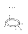
- the Oldham coupling member 35 is in a ring shape as shown in Fig.4, and has a pair of projections 37, 37 on the top side thereof and another pair of projections 39, 39 on the bottom side. Moreover, each upper projection 37 is shifted by 90 from each lower projection 39, and each upper projection 37 is engaged in each first groove 41 formed in the boss 31 of the rotary member 29. On the other hand, each lower projection 39 is engaged in each second groove 43 which is formed in the second bearing member 21 and shifted by 90 from each first groove 41.
- a spiral groove 45 along the axis thereof, and the pitch of the groove 45 is so arranged as to be the maximum at the portion nearest to the suction pipe 5 and to be the minimum at the portion nearest to the discharge pipe 7.
- a blade 47 formed with an elastomeric material such as synthetic resins so as to enable the blade 47 to vertically move in the groove 45 by the elastic properties of the material.
- the length of the blade 47 is a little shorter than that of the spiral groove 45, and the width is almost the same as that of the spiral groove.
- the thickness is smaller than the depth of the groove, therefore, the blade 47 can move vertically (in a direction shown by an arrow B in Fig.3) within the space defined between the bottom of the groove and the inner surface of the cylinder 27.
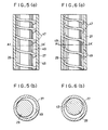
- each operation chamber is defined between each adjacent pair of contact portions of the blade 47 to the inner surface of the cylinder 47 as shown in Fig.5a, and the cross section is in a shape of a crescent as shown in Fig.5b.
- each operation chamber is the maximum at the portion the nearest to the suction pipe 5 (at the lowest operation chamber shown in Fig.3), and becomes gradually smaller toward the portion the nearest to the discharge pipe 7 (toward the top operation chamber shown in Fig.3).
- the lowest or first operation chamber 49 on the inlet side is in communication with the suction pipe 5, and a refrigerant gas is continuously supplied thereto from the pipe 5.
- the top or last operation chamber 49 on the discharge side communicates with the discharge pipe 7 through an opening 51 formed through the first bearing member 17.
- reference numeral 53 designates a balance weight provided at the main shaft 25, and 55 shows lubricant oil to be supplied to the respective bearing sections 19, 23.
- the diameter of the cylinder 27 is so set as to enlarge the capacity of the first chamber 49, the contact between the blade 7 and the inner surface of the cylinder 27 is so smooth that stable operation can be maintained for a long period of time. Moreover, on the compression of the refrigerant gas, the gas pressure acting on the cylinder 27 has no influence on the respective bearing sections 19, 23.
- the force designated by an arrow F in Fig.3, which is generated by the refrigerant gas on the compression is transmitted to the eccentric shaft 33 of the main shaft 25 through the boss 31.
- the eccentric shaft 33 is positioned in an area where the gas force F is to act, the bending moment to be applied to the rotary member 29 can be suppressed at a relatively small value.
- the main shaft 25 is supported by the two bearing sections 19, 23, the bending moment to be applied to the main shaft 25 can be also suppressed, thereby to obtain stable rotation movement thereof.
- the present invention is used for a vertical type fluid compressor, it can be also used for the horizontal type or vacuum pumps.
- the present invention it becomes possible to enlarge the diameter of the cylinder by fixing it to the case and orbiting the rotor only.
- the operational efficiency of the system can be greatly improved by enlarging the first operation chamber the nearest to the inlet end without twisting the blade excessively.
- the blade can be flexibly fitted in the spiral groove, it becomes possible to prevent concentration of load to a specific portion of the blade, so that stable operation of the system can be maintained for a long period of time.
- the system structure is so constructed as to suppress the load to be imposed on the bearing sections, the rotary system can be operated more stably and smoothly than the conventional systems.
Landscapes
- Engineering & Computer Science (AREA)
- Mechanical Engineering (AREA)
- General Engineering & Computer Science (AREA)
- Rotary Pumps (AREA)
Applications Claiming Priority (2)
| Application Number | Priority Date | Filing Date | Title |
|---|---|---|---|
| JP2168529A JP2888936B2 (ja) | 1990-06-28 | 1990-06-28 | 流体圧縮機 |
| JP168529/90 | 1990-06-28 |
Publications (1)
| Publication Number | Publication Date |
|---|---|
| EP0464683A1 true EP0464683A1 (fr) | 1992-01-08 |
Family
ID=15869714
Family Applications (1)
| Application Number | Title | Priority Date | Filing Date |
|---|---|---|---|
| EP91110680A Withdrawn EP0464683A1 (fr) | 1990-06-28 | 1991-06-27 | Compresseur à fluide |
Country Status (4)
| Country | Link |
|---|---|
| US (1) | US5174737A (fr) |
| EP (1) | EP0464683A1 (fr) |
| JP (1) | JP2888936B2 (fr) |
| KR (1) | KR950008018B1 (fr) |
Cited By (3)
| Publication number | Priority date | Publication date | Assignee | Title |
|---|---|---|---|---|
| WO1999017023A3 (fr) * | 1997-09-30 | 1999-06-17 | Toshiba Kk | Compresseur a fluide |
| US6354825B1 (en) | 1997-09-30 | 2002-03-12 | Kabushiki Kaisha Toshiba | Helical blade fluid compressor having an aluminum alloy rotating member |
| DE10212940A1 (de) * | 2002-03-22 | 2003-10-02 | Leybold Vakuum Gmbh | Exzenterpumpe und Verfahren zum Betrieb dieser Pumpe |
Families Citing this family (15)
| Publication number | Priority date | Publication date | Assignee | Title |
|---|---|---|---|---|
| JP3212674B2 (ja) * | 1992-03-26 | 2001-09-25 | 東芝キヤリア株式会社 | 流体圧縮機 |
| JP3290224B2 (ja) * | 1993-01-12 | 2002-06-10 | 東芝キヤリア株式会社 | 流体圧縮機 |
| US5780010A (en) * | 1995-06-08 | 1998-07-14 | Barnes-Jewish Hospital | Method of MRI using avidin-biotin conjugated emulsions as a site specific binding system |
| US6821506B2 (en) * | 1995-06-08 | 2004-11-23 | Barnes-Jewish Hospital | Site specific binding system, imaging compositions and methods |
| JPH1061564A (ja) * | 1996-08-20 | 1998-03-03 | Atsushi Imai | 螺旋状シールを利用したポンプ |
| JPH10196566A (ja) * | 1997-01-10 | 1998-07-31 | Toshiba Corp | 流体圧縮機 |
| JPH11107952A (ja) * | 1997-10-03 | 1999-04-20 | Toshiba Corp | 流体機械 |
| US6162035A (en) * | 1997-10-03 | 2000-12-19 | Kabushiki Kaisha Toshiba | Helical-blade fluid machine |
| JPH11125193A (ja) * | 1997-10-22 | 1999-05-11 | Toshiba Corp | 流体機械 |
| TW411382B (en) * | 1997-10-23 | 2000-11-11 | Toshiba Corp | Helical compressor and method of assembling the same |
| KR100341238B1 (ko) * | 2000-06-30 | 2002-06-20 | 백관석 | 참나무과 식물잎의 추출물을 함유하는 술 |
| JP2002062020A (ja) * | 2000-08-17 | 2002-02-28 | Toshiba Corp | 冷蔵庫 |
| JP2003003979A (ja) * | 2001-06-25 | 2003-01-08 | Toshiba Kyaria Kk | 流体機械 |
| US9309862B2 (en) * | 2013-11-25 | 2016-04-12 | Halliburton Energy Services, Inc. | Nutating fluid-mechanical energy converter |
| CN107740766B (zh) * | 2017-09-30 | 2020-12-01 | 山东海伦食品有限公司 | 一种摆动结构恒速空压机 |
Citations (1)
| Publication number | Priority date | Publication date | Assignee | Title |
|---|---|---|---|---|
| EP0301273A2 (fr) * | 1987-07-31 | 1989-02-01 | Kabushiki Kaisha Toshiba | Compresseur à fluide |
Family Cites Families (4)
| Publication number | Priority date | Publication date | Assignee | Title |
|---|---|---|---|---|
| US2358721A (en) * | 1940-05-22 | 1944-09-19 | Ljungdahl Oskar Birger | Pump, compressor, motor, or the like |
| US2401189A (en) | 1944-05-12 | 1946-05-28 | Francisco A Quiroz | Rotary pump construction |
| US2764101A (en) * | 1952-05-27 | 1956-09-25 | Rand Dev Corp | Helical pump |
| US3274944A (en) * | 1965-09-30 | 1966-09-27 | Frederick L Parsons | Screw vane pump |
-
1990
- 1990-06-28 JP JP2168529A patent/JP2888936B2/ja not_active Expired - Fee Related
-
1991
- 1991-06-27 EP EP91110680A patent/EP0464683A1/fr not_active Withdrawn
- 1991-06-27 US US07/721,753 patent/US5174737A/en not_active Expired - Lifetime
- 1991-07-01 KR KR1019910011080A patent/KR950008018B1/ko not_active Expired - Fee Related
Patent Citations (1)
| Publication number | Priority date | Publication date | Assignee | Title |
|---|---|---|---|---|
| EP0301273A2 (fr) * | 1987-07-31 | 1989-02-01 | Kabushiki Kaisha Toshiba | Compresseur à fluide |
Cited By (5)
| Publication number | Priority date | Publication date | Assignee | Title |
|---|---|---|---|---|
| WO1999017023A3 (fr) * | 1997-09-30 | 1999-06-17 | Toshiba Kk | Compresseur a fluide |
| US6354825B1 (en) | 1997-09-30 | 2002-03-12 | Kabushiki Kaisha Toshiba | Helical blade fluid compressor having an aluminum alloy rotating member |
| CN1087401C (zh) * | 1997-09-30 | 2002-07-10 | 东芝株式会社 | 流体压缩机 |
| DE10212940A1 (de) * | 2002-03-22 | 2003-10-02 | Leybold Vakuum Gmbh | Exzenterpumpe und Verfahren zum Betrieb dieser Pumpe |
| US7186098B2 (en) | 2002-03-22 | 2007-03-06 | Oerlikon Leybold Vacuum Gmbh | Eccentric pump and method for operation of said pump |
Also Published As
| Publication number | Publication date |
|---|---|
| KR920005748A (ko) | 1992-04-03 |
| KR950008018B1 (ko) | 1995-07-24 |
| JPH0458086A (ja) | 1992-02-25 |
| US5174737A (en) | 1992-12-29 |
| JP2888936B2 (ja) | 1999-05-10 |
Similar Documents
| Publication | Publication Date | Title |
|---|---|---|
| US5174737A (en) | Fluid compressor with spiral blade | |
| EP0301273B1 (fr) | Compresseur à fluide | |
| JP2712914B2 (ja) | スクロール圧縮機 | |
| US4836758A (en) | Scroll compressor with canted drive busing surface | |
| EP0009355A1 (fr) | Compresseurs du type à spirale | |
| US4585403A (en) | Scroll device with eccentricity adjusting bearing | |
| EP0049495B1 (fr) | Appareil à déplacement de fluide à volutes imbriquées | |
| US5178527A (en) | Lubricating apparatus for scroll-type compressor | |
| EP2628956A2 (fr) | Machine de défilement de fluide | |
| EP0376049B1 (fr) | Compresseur à fluide | |
| EP0381061B1 (fr) | Compresseur de fluide | |
| JP2734408B2 (ja) | スクロール圧縮機 | |
| EP0172674A1 (fr) | Compresseur à fluide du type à spirales imbriquées | |
| US4904169A (en) | Scroll type compressing apparatus having strengthened scroll member | |
| JPH09195956A (ja) | スクロール圧縮機 | |
| JP3112326B2 (ja) | 流体圧縮機 | |
| KR102548470B1 (ko) | 올담링을 구비한 압축기 | |
| KR100297994B1 (ko) | 헬리컬블레이드식유체압축기 | |
| KR102492951B1 (ko) | 올담링을 구비한 압축기 | |
| JP3487612B2 (ja) | 流体圧縮機 | |
| JP3574904B2 (ja) | 密閉式容積形圧縮機 | |
| JP2888935B2 (ja) | 流体圧縮機 | |
| JP3110831B2 (ja) | 流体圧縮機 | |
| JPH0732951Y2 (ja) | 流体圧縮機 | |
| JP3078269B2 (ja) | 流体圧縮機 |
Legal Events
| Date | Code | Title | Description |
|---|---|---|---|
| PUAI | Public reference made under article 153(3) epc to a published international application that has entered the european phase |
Free format text: ORIGINAL CODE: 0009012 |
|
| 17P | Request for examination filed |
Effective date: 19910627 |
|
| AK | Designated contracting states |
Kind code of ref document: A1 Designated state(s): DE FR IT |
|
| 17Q | First examination report despatched |
Effective date: 19920729 |
|
| STAA | Information on the status of an ep patent application or granted ep patent |
Free format text: STATUS: THE APPLICATION IS DEEMED TO BE WITHDRAWN |
|
| 18D | Application deemed to be withdrawn |
Effective date: 19921130 |