EP0464731A2 - Dispositif de commande de soupape électromagnétique - Google Patents
Dispositif de commande de soupape électromagnétique Download PDFInfo
- Publication number
- EP0464731A2 EP0464731A2 EP19910110840 EP91110840A EP0464731A2 EP 0464731 A2 EP0464731 A2 EP 0464731A2 EP 19910110840 EP19910110840 EP 19910110840 EP 91110840 A EP91110840 A EP 91110840A EP 0464731 A2 EP0464731 A2 EP 0464731A2
- Authority
- EP
- European Patent Office
- Prior art keywords
- electromagnetic valve
- control device
- voltage
- output
- resistor
- Prior art date
- Legal status (The legal status is an assumption and is not a legal conclusion. Google has not performed a legal analysis and makes no representation as to the accuracy of the status listed.)
- Withdrawn
Links
Images

Classifications
-
- F—MECHANICAL ENGINEERING; LIGHTING; HEATING; WEAPONS; BLASTING
- F02—COMBUSTION ENGINES; HOT-GAS OR COMBUSTION-PRODUCT ENGINE PLANTS
- F02D—CONTROLLING COMBUSTION ENGINES
- F02D41/00—Electrical control of supply of combustible mixture or its constituents
- F02D41/22—Safety or indicating devices for abnormal conditions
-
- F—MECHANICAL ENGINEERING; LIGHTING; HEATING; WEAPONS; BLASTING
- F02—COMBUSTION ENGINES; HOT-GAS OR COMBUSTION-PRODUCT ENGINE PLANTS
- F02D—CONTROLLING COMBUSTION ENGINES
- F02D41/00—Electrical control of supply of combustible mixture or its constituents
- F02D41/20—Output circuits, e.g. for controlling currents in command coils
-
- F—MECHANICAL ENGINEERING; LIGHTING; HEATING; WEAPONS; BLASTING
- F02—COMBUSTION ENGINES; HOT-GAS OR COMBUSTION-PRODUCT ENGINE PLANTS
- F02D—CONTROLLING COMBUSTION ENGINES
- F02D41/00—Electrical control of supply of combustible mixture or its constituents
- F02D41/20—Output circuits, e.g. for controlling currents in command coils
- F02D2041/202—Output circuits, e.g. for controlling currents in command coils characterised by the control of the circuit
- F02D2041/2024—Output circuits, e.g. for controlling currents in command coils characterised by the control of the circuit the control switching a load after time-on and time-off pulses
- F02D2041/2027—Control of the current by pulse width modulation or duty cycle control
-
- Y—GENERAL TAGGING OF NEW TECHNOLOGICAL DEVELOPMENTS; GENERAL TAGGING OF CROSS-SECTIONAL TECHNOLOGIES SPANNING OVER SEVERAL SECTIONS OF THE IPC; TECHNICAL SUBJECTS COVERED BY FORMER USPC CROSS-REFERENCE ART COLLECTIONS [XRACs] AND DIGESTS
- Y02—TECHNOLOGIES OR APPLICATIONS FOR MITIGATION OR ADAPTATION AGAINST CLIMATE CHANGE
- Y02T—CLIMATE CHANGE MITIGATION TECHNOLOGIES RELATED TO TRANSPORTATION
- Y02T10/00—Road transport of goods or passengers
- Y02T10/10—Internal combustion engine [ICE] based vehicles
- Y02T10/40—Engine management systems
Definitions
- the invention relates to a device and a method for controlling an electromagnetic valve according to the preamble of the independent claims.
- the electromagnetic control valve In the event of a failure or defect in the control electronics or the power output stage (short circuit), the electromagnetic control valve remains open and the fuel can flow to a burner or into a combustion chamber in an uncontrolled manner.
- electromagnetic valves When electromagnetic valves are used to supply fuel to an internal combustion engine, this uncontrolled flow of fuel leads to overturning and thus to damage or destruction of the internal combustion engine.
- electromagnetic valves When using electromagnetic valves to supply fuel to a burner, in addition to increased fuel consumption, there is a very high risk of fire and explosion.
- the invention has for its object to provide a device and a method with which a failure or defect of the control electronics or the power output stage is recognized and a malfunction of the electromagnetic control valve resulting therefrom is avoided.
- the object of the invention is achieved in that an output of the control device leading to the electromagnetic valve is connected to the input of a protective device, of which an output is connected to a switching device, the switching device being mounted in a voltage supply line.
- a protective device of which an output is connected to a switching device, the switching device being mounted in a voltage supply line.
- the control device finds particular application in monitoring the regeneration of particle filters of a diesel internal combustion engine, in which the regeneration is carried out at least as a function of the quantity of fuel supplied to the burner by means of the electromagnetic valve. In the event of a fault in the supply of fuel (defective control of the valve), damage to the particulate filter in particular or the burner is avoided.
- the switching device is connected between the voltage source and the input of the power output stage or is attached between the output of the power output stage and the electromagnetic valve.
- the power output stage of the control device is designed as a transistor, the transistor being controlled by the control electronics, this has the advantage that the control electronics form clock signals corresponding to the detected operating parameters of the internal combustion engine or convert them into digital signals which are output to the power output stage in a clocked or preferably pulse-width-modulated manner. This enables precise and effective control of the electromagnetic valve.
- an output voltage of the power output stage, which controls the electromagnetic valve can be fed to the protective device. This has the advantage that the protective device checks this output voltage for correctness or defect.
- the protective device consists of a circuit for generating a switching signal with which a downstream switching device is controlled. After detection of an abnormal output voltage due to a short circuit in the power output stage or the control electronics, it is thus possible to switch off the voltage supply to the electromagnetic valve, so that an unimpeded flow of fuel through the open valve is prevented.
- the circuit has a first resistor, which is connected to the line of the voltage supply and via a capacitor to ground, and a second resistor, which is connected via a diode between the output of the power output stage and the ground of the voltage source. Furthermore, the connection of the second resistor facing away from ground is connected via a diode to the connection point of the capacitor and the first resistor. Furthermore, the circuit has a comparison device, to which a reference voltage and the voltage across the capacitor are supplied. The comparison device is advantageously an operational amplifier. The reference voltage is generated by a voltage divider consisting of a third and fourth resistor, the voltage divider being arranged between the supply voltage line and the ground of the voltage source.
- the output of the operational amplifier leads to the circuit device, the output signal of the operational amplifier being fed to the switching device via a diode.
- This switching device preferably consists of a relay which is controlled via a transistor by the output signal of the operational amplifier.
- the capacitor When operating properly (clocked valve), the capacitor is periodically discharged via the diode and the second resistor in the switch-off phases of the transistor in the power output stage.
- the first resistor has a high resistance to the second resistor, so that only a small residual voltage remains on the capacitor. If the electromagnetic valve is continuously controlled by a defect, the connection point of the two diodes is kept at a high voltage via the diode which is connected to the output of the power output stage, as a result of which the capacitor does not periodically discharge.
- the condenser charges via the first resistor until the switching threshold of the operational amplifier is exceeded.
- an output signal can be fed from the operational amplifier connected as a comparator to a switching device which separates the control device directly from the voltage source, so that the uncontrolled fuel flow is interrupted.
- the transistor for the relay After switching off the power supply and at the same time switching on the power supply to the voltage divider, the transistor for the relay remains conductive (self-holding function), so that the protective function of the protective circuit remains fully intact and the defect must first be remedied.
- a warning signal e.g. acoustically or optically
- control device can alternatively be used in a fuel injection device of an internal combustion engine or in the control of a burner, in particular a burner of a particle filter system.
- a particular area of application is the monitoring of the electromagnetic valves of the fuel injection device of a diesel internal combustion engine and the at least one electromagnetic valve of the diesel particle filter system connected downstream of the diesel internal combustion engine.
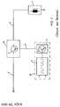
- FIG. 1 shows a control device for an electromagnetic valve according to the prior art.
- An electromagnetic valve 1 is connected via a feed line 2 to the output of a power output stage 3b of the control device 3.
- the power output stage 3b consists of a power transistor 4, the power output stage 3b being connected to a voltage source 28 via a voltage supply line 5.
- the control device 3 further comprises control electronics 3a, which is divided into a clock circuit 6 and a control stage 7. Operating parameters of the internal combustion engine are recorded by the clock circuit 6 and converted into clock signals, which are passed on to the control stage 7, which can consist of a control transistor 8.
- the entire control electronics 3a is connected via a control line 9 to an input of the power output stage 3b.
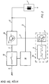
- FIG. 2 shows a control device according to the invention for an electromagnetic valve, a protective device 10 and a switching device 12 being present in addition to the components shown in FIG. 1.
- the protective device 10 is connected via a connecting line 11 to an output of the power output stage 3b, while the switching device 12 is connected directly downstream of the protective device 10. From an output of the power stage 3b the output voltage of the power output stage 3b of the protective device 10 is supplied via the supply line 2 and the connecting line 11.
- the protective device 10 which is explained in more detail in FIG. 3, evaluates the output voltage and outputs an output signal corresponding to the evaluation to the switching device 12, which is attached in the voltage supply line 5 between the voltage source 28 and an input of the power output stage 3b.
- FIG. 3 shows the circuit of the protective device 10 according to the invention.
- the anode of a diode 13 is connected to an output of the power output stage 3b, shown here as a collector of a transistor 4, while the cathode of the diode 1 is connected via a resistor 14 is connected to ground.
- the connection point of the diode 13 and the resistor 14 is connected to a first reference point 16 via a further diode 15.
- a resistor 17 is connected between the first reference point 16 and the voltage supply line 5, which leads to an input of the power output stage 3b, which is shown here as the emitter of the transistor 4.
- a capacitor 18 is connected to ground from the first reference point 16.
- a voltage divider is implemented from the voltage supply line 5 via resistors 19 and 20 to ground, the output voltage of the voltage divider being tapped at a point 21.
- a further part of the circuit is connected downstream of this first part of the circuit, the further part consisting of an operational amplifier 22 and a diode 23.
- the switching device is assigned a further voltage divider, consisting of resistors 24 and 25, as well as a transistor 26 and a relay 27.
- the inverting input of operational amplifier 22 is connected to point 21, so that this input of operational amplifier 22 is one with the resistors 19 and 20 adjustable reference voltage can be supplied.
- the non-inverting input of the operational amplifier 22 is connected to the first reference point 16, at which the voltage applied to the capacitor 18 is tapped.
- the output of the operational amplifier 22 is connected via a diode 23 to the center of the voltage divider of the switching device 12, consisting of the resistors 24 and 25. From this point, the gate of transistor 26 is driven while the source of transistor 26 is connected to ground. The drain of transistor 26 is connected to the voltage source via the excitation coil of relay 27.
- the relay 27 has a changeover contact, which is connected on the one hand to the voltage supply line 5 and, on the other hand, is connected to the resistor 24 after the changeover process.
- the circuit works as follows: If the control electronics 3a, the control stage 7 and the power output stage 3b function correctly, the capacitor 18 is charged via the resistor 17 and discharged via the resistor 14. For the respective clock signals with which the electromagnetic valve 1 is controlled, the capacitor 18 will charge slowly during a switch-on phase (high potential of the clock signal) and discharge very quickly during a switch-off phase (low potential). Due to the very rapid discharge of the capacitor 18, only a small residual voltage arises at the first reference point 16. If the drive transistor 8 or the power transistor 4 should have a short circuit, the supply voltage is connected to the electromagnetic valve 1 and the resistor 14, so that the capacitor 18 can no longer discharge. This will further charge the capacitor, causing the capacitor voltage present at the first reference point 16 continues to rise.
- the output of operational amplifier 22 switches, so that transistor 26 becomes conductive.
- the normally open contact of the relay 27 switches from the voltage supply line 5 to the resistor 24, so that the electromagnetic valve 1 is disconnected from the voltage source.
- the transistor 26 remains conductive (self-holding function). Only after switching off the power supply does the relay 27 drop out and interrupt its self-holding circuit. If the supply voltage is switched on again without the fault being eliminated, the protective device switches off again.
- a reset button can be used, for example, which interrupts the latch circuit of the relay 27.
- a warning signal which indicates that there is a defect in the control device 3 for the electromagnetic valve 1.
- This can be done, for example, in that the output signal of the operational amplifier 22 is passed via a further transistor which, optionally via a relay, can actuate an optical or acoustic warning device (not shown).
- the detected variables are, for example, operating variables of the internal combustion engine or the fuel injection device (pressure, temperature, speed, voltage, time variable of the electromagnetic valve) and other suitable variables and their change or limit values.
- Operating variables of the particle filter system for example temperature upstream and downstream of the filter or the exhaust gas back pressure, for example) can also be used.
Landscapes
- Engineering & Computer Science (AREA)
- Chemical & Material Sciences (AREA)
- Combustion & Propulsion (AREA)
- Mechanical Engineering (AREA)
- General Engineering & Computer Science (AREA)
- Electrical Control Of Air Or Fuel Supplied To Internal-Combustion Engine (AREA)
Applications Claiming Priority (1)
| Application Number | Priority Date | Filing Date | Title |
|---|---|---|---|
| DE4020836A DE4020836A1 (de) | 1990-06-29 | 1990-06-29 | Steuervorrichtung fuer ein elektromagnetisches ventil |
Publications (2)
| Publication Number | Publication Date |
|---|---|
| EP0464731A2 true EP0464731A2 (fr) | 1992-01-08 |
| EP0464731A3 EP0464731A3 (en) | 1993-03-31 |
Family
ID=6409395
Family Applications (1)
| Application Number | Title | Priority Date | Filing Date |
|---|---|---|---|
| EP19910110840 Withdrawn EP0464731A3 (en) | 1990-06-29 | 1991-06-28 | Control apparatus for an electromagnetic valve |
Country Status (2)
| Country | Link |
|---|---|
| EP (1) | EP0464731A3 (fr) |
| DE (1) | DE4020836A1 (fr) |
Cited By (2)
| Publication number | Priority date | Publication date | Assignee | Title |
|---|---|---|---|---|
| WO1995007409A1 (fr) * | 1993-09-07 | 1995-03-16 | Robert Bosch Gmbh | Procede de diagnostic de defaillance des injecteurs de systemes d'injection a haute pression de moteurs a combustion interne |
| US5725949A (en) * | 1995-03-11 | 1998-03-10 | Akzo Nobel Nv | Hollow-fiber bundle and mass-transfer and/or heat exchanger |
Families Citing this family (1)
| Publication number | Priority date | Publication date | Assignee | Title |
|---|---|---|---|---|
| DE102008023198A1 (de) * | 2008-05-10 | 2009-11-12 | Robert Bosch Gmbh | Hydraulikventilsteuergerät und Verfahren zum Überprüfen eines Hydraulikventilsteuergeräts |
Family Cites Families (13)
| Publication number | Priority date | Publication date | Assignee | Title |
|---|---|---|---|---|
| IT1001997B (it) * | 1973-11-28 | 1976-04-30 | Circuito di pilotaggio per elet tromagnete di stampa | |
| DE2426512C2 (de) * | 1974-05-31 | 1983-12-01 | Krauss-Maffei AG, 8000 München | Einrichtung zum Schalten eines elektrohydraulischen Wegventils |
| DD142738A1 (de) * | 1979-04-04 | 1980-07-09 | Gerhard Haase | Einrichtung zum ansteuern eines abstellelementes fuer elektronische einspritzanlagen |
| US4509091A (en) * | 1984-02-17 | 1985-04-02 | Warner Electric Brake & Clutch Company | Methods and apparatus for controlling the engagement of gap-type electromagnetic couplings |
| GB8406331D0 (en) * | 1984-03-10 | 1984-04-11 | Lucas Ind Plc | Control system |
| GB8502705D0 (en) * | 1985-02-02 | 1985-03-06 | Ford Motor Co | Driver circuit for solenoids |
| JPH0629598B2 (ja) * | 1985-03-04 | 1994-04-20 | トヨタ自動車株式会社 | デイ−ゼルエンジンの燃料噴射フエイルセイフ装置 |
| DE3509961A1 (de) * | 1985-03-20 | 1986-09-25 | Robert Bosch Gmbh, 7000 Stuttgart | Schaltungsanordnung zur steuerung des stromes durch einen elektrischen, insbesondere elektromagnetischen verbraucher |
| US4589401A (en) * | 1985-04-12 | 1986-05-20 | Motorola, Inc. | Injector driver fault detect and protection device |
| JPH0663471B2 (ja) * | 1986-02-13 | 1994-08-22 | 本田技研工業株式会社 | 内燃機関の補助空気量制御装置 |
| US4736267A (en) * | 1986-11-14 | 1988-04-05 | Motorola, Inc. | Fault detection circuit |
| DE3811515A1 (de) * | 1988-04-06 | 1989-10-19 | Vdo Schindling | Elektrisches stellglied fuer das leistungsstellelement einer brennkraftmaschine |
| DE3909141A1 (de) * | 1989-03-21 | 1990-09-27 | Bosch Gmbh Robert | Schaltungsanordnung fuer den betrieb eines elektromagnetischen verbrauchers |
-
1990
- 1990-06-29 DE DE4020836A patent/DE4020836A1/de not_active Withdrawn
-
1991
- 1991-06-28 EP EP19910110840 patent/EP0464731A3/de not_active Withdrawn
Cited By (2)
| Publication number | Priority date | Publication date | Assignee | Title |
|---|---|---|---|---|
| WO1995007409A1 (fr) * | 1993-09-07 | 1995-03-16 | Robert Bosch Gmbh | Procede de diagnostic de defaillance des injecteurs de systemes d'injection a haute pression de moteurs a combustion interne |
| US5725949A (en) * | 1995-03-11 | 1998-03-10 | Akzo Nobel Nv | Hollow-fiber bundle and mass-transfer and/or heat exchanger |
Also Published As
| Publication number | Publication date |
|---|---|
| EP0464731A3 (en) | 1993-03-31 |
| DE4020836A1 (de) | 1992-01-02 |
Similar Documents
| Publication | Publication Date | Title |
|---|---|---|
| EP1185917B1 (fr) | Circuit d'un dispositif de commande pour la surveillance d'une tension | |
| DE3313036C2 (de) | Vorrichtung zur Verhinderung des klopfenden Betriebs bei Brennkraftmaschinen | |
| EP0101850B1 (fr) | Dispositif de secours pour la marche au ralenti de camions | |
| DE68905378T2 (de) | Steuerschaltung fuer die energieversorgung einer elektrischen last mit einer erfassungsanordnung eines kurzschlusses der last. | |
| DE4219339C2 (de) | Abgasrückführungsvorrichtung mit Fehlerdiagnose | |
| DE3785439T2 (de) | Verfahren und geraet zur feststellung und anzeige von zuendungsanomalien beim betrieb von zuendsystemen von verbrennungsmaschinen, insbesondere fuer mit einem katalysator ausgestattete motorfahrzeuge. | |
| DE60309551T2 (de) | Kraftstoffversorgungssystem mit elektromagnetischem Einspritzventil | |
| EP0670959B1 (fr) | Systeme de protection pour un moteur a combustion interne suralimente | |
| DE19906287A1 (de) | Verfahren und Steuerung einer Brennkraftmaschine mit einem Abgasnachbehandlungssystems | |
| DE19500452B4 (de) | Verfahren und Vorrichtung zur Überwachung der Funktionsfähigkeit eines Leerlaufstellers | |
| DE19743667A1 (de) | Anordnung zum Regeln des Ladedrucks einer Brennkraftmaschine | |
| DE3128475C2 (fr) | ||
| DE102009051390A1 (de) | Verfahren zur Steuerung und Regelung einer Brennkraftmaschine | |
| EP0417383B1 (fr) | Procédé et dispositif de nettoyage d'un filtre à suie | |
| DE3327376C2 (de) | Verfahren und Vorrichtung zur Steuerung der Stellung einer Drosselklappe in Ansaugrohr einer Brennkraftmaschine | |
| DE10064505A1 (de) | Verfahren und Vorrichtung zur Überwachung eines Abstands zwischen zwei Einspritzvorgängen | |
| DE19810525C2 (de) | Verfahren und Vorrichtung zum Ansteuern kapazitiver Stellglieder | |
| DE10014224A1 (de) | Verfahren und Vorrichtung zur Steuerung einer Brennkraftmaschine mit einem Abgasnachbehandlungssytem | |
| DE2618028C2 (de) | Universell einsetzbares, in integrierter Schaltkreistechnik ausführbares Zeitglied | |
| DE102004036388A1 (de) | Verfahren zum Betreiben einer Brennkraftmaschine, bei dem die Beladung eines Abgasstroms mit Rußpartikeln erfasst wird | |
| EP0567060A1 (fr) | Procédé pour commander un brûleur à gaz avec un ventilateur | |
| DE10028353A1 (de) | Verfahren zur Überprüfung eines kapazitiven Stellgliedes | |
| DE2823788C2 (fr) | ||
| EP1180210A1 (fr) | Procede et dispositif pour commander un moteur a combustion interne equipe d'un systeme de retraitement des gaz d'echappement | |
| DE19958406A1 (de) | Verfahren und Vorrichtung zur Steuerung eines Stellers mit einem kapazitiven Element |
Legal Events
| Date | Code | Title | Description |
|---|---|---|---|
| PUAI | Public reference made under article 153(3) epc to a published international application that has entered the european phase |
Free format text: ORIGINAL CODE: 0009012 |
|
| AK | Designated contracting states |
Kind code of ref document: A2 Designated state(s): DE ES FR GB IT NL SE |
|
| RAP1 | Party data changed (applicant data changed or rights of an application transferred) |
Owner name: KLOECKNER-HUMBOLDT-DEUTZ AG |
|
| RIN1 | Information on inventor provided before grant (corrected) |
Inventor name: AKBARIAN, TAGHI Inventor name: WALLENFANG, GERD |
|
| PUAL | Search report despatched |
Free format text: ORIGINAL CODE: 0009013 |
|
| AK | Designated contracting states |
Kind code of ref document: A3 Designated state(s): DE ES FR GB IT NL SE |
|
| STAA | Information on the status of an ep patent application or granted ep patent |
Free format text: STATUS: THE APPLICATION IS DEEMED TO BE WITHDRAWN |
|
| 18D | Application deemed to be withdrawn |
Effective date: 19931001 |