EP0464748A2 - Vorrichtung zur Erfassung eines Batteriezustandes und Ladegerät für Autos - Google Patents
Vorrichtung zur Erfassung eines Batteriezustandes und Ladegerät für Autos Download PDFInfo
- Publication number
- EP0464748A2 EP0464748A2 EP91110879A EP91110879A EP0464748A2 EP 0464748 A2 EP0464748 A2 EP 0464748A2 EP 91110879 A EP91110879 A EP 91110879A EP 91110879 A EP91110879 A EP 91110879A EP 0464748 A2 EP0464748 A2 EP 0464748A2
- Authority
- EP
- European Patent Office
- Prior art keywords
- battery
- capacity
- current
- charge
- detecting
- Prior art date
- Legal status (The legal status is an assumption and is not a legal conclusion. Google has not performed a legal analysis and makes no representation as to the accuracy of the status listed.)
- Granted
Links
Images


Classifications
-
- G—PHYSICS
- G01—MEASURING; TESTING
- G01R—MEASURING ELECTRIC VARIABLES; MEASURING MAGNETIC VARIABLES
- G01R31/00—Arrangements for testing electric properties; Arrangements for locating electric faults; Arrangements for electrical testing characterised by what is being tested not provided for elsewhere
- G01R31/36—Arrangements for testing, measuring or monitoring the electrical condition of accumulators or electric batteries, e.g. capacity or state of charge [SoC]
- G01R31/3644—Constructional arrangements
- G01R31/3648—Constructional arrangements comprising digital calculation means, e.g. for performing an algorithm
-
- G—PHYSICS
- G01—MEASURING; TESTING
- G01R—MEASURING ELECTRIC VARIABLES; MEASURING MAGNETIC VARIABLES
- G01R31/00—Arrangements for testing electric properties; Arrangements for locating electric faults; Arrangements for electrical testing characterised by what is being tested not provided for elsewhere
- G01R31/36—Arrangements for testing, measuring or monitoring the electrical condition of accumulators or electric batteries, e.g. capacity or state of charge [SoC]
- G01R31/382—Arrangements for monitoring battery or accumulator variables, e.g. SoC
- G01R31/3842—Arrangements for monitoring battery or accumulator variables, e.g. SoC combining voltage and current measurements
-
- G—PHYSICS
- G01—MEASURING; TESTING
- G01R—MEASURING ELECTRIC VARIABLES; MEASURING MAGNETIC VARIABLES
- G01R31/00—Arrangements for testing electric properties; Arrangements for locating electric faults; Arrangements for electrical testing characterised by what is being tested not provided for elsewhere
- G01R31/005—Testing of electric installations on transport means
- G01R31/006—Testing of electric installations on transport means on road vehicles, e.g. automobiles or trucks
Definitions
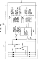
- reference nuemral 1 indicates a battery mounted on an automobile; reference numeral 2 denotes an engine for driving the automobile, reference numeral 3 represents a starter for starting the engine; reference numeral 4 indicates a starter switch for commencing the start. As is well known, by turning on the starter switch 4 so as to supply power from the battery 1 to the starter 3, this starter 3 is rotated and the engine 2 starts.
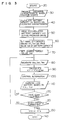
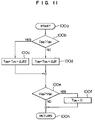
- the above-described discharge current I B1 , voltage V B1 and time "t" of the battery 1 are stored into the discharge characteristic calculating unit 9e functioning as a first means for detecting a battery capacity.
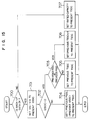
- the operations as defined from the above-described steps 305 to 308 are interrupted. If three seconds have not yet elapsed after the starter 3 starts, the process is again returned to a step 305.
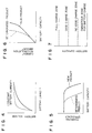
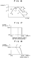
- the first battery capacity VI1 is larger than the third battery capacity VI3 by a predetermined value. If such a phenomenon that concentration of the battery liquid near the electrode becomes high just after the specific gravity of the battery liquid become electrolyte stratification or the battery is charged (will be referred to as a "polarization") happens to occur, the voltage characteristic with respect to the capacity is indicated by a dot line shown in Fig. 4. In other words, when either electrolyte stratification, or polarization happens to occur, the resultant battery voltage becomes higher than the normal battery voltage.
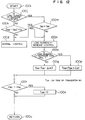
- a detection is made whether or not the load suddenly-change control is under operation at present time. Since this is cleared when an IG (ignition) switch (not shown) is turned ON, a detection is made of a difference between either the charge current or discharge current I B2 of the battery 1, and the control charge current I BC thereof at the next step 100k.
- IG ignition
- the problems such as an increase in the engine revolution may be prevented because the load given to the engine 2 is suddenly decreased, by surely detecting such a case that the electric load 8 is interrupted during the idling operation, by gradually decreasing the power generated by the alternator 5 at this time instant, during which the charge current to the battery 1 is increased, whereby it may be avoided that the load given to the engine 2 is suddently decreased.
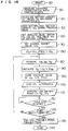
- the control voltage V BC is set to such a control voltage lower than the control voltage V BC by 2V which has been set before the acceleration, and also the control charge current I BC is set to O(A), so that the power generated by the alternator 5 is decreased and the acceleration characteristic is improved.
- the control charge current I BC is set to 30A.
- the second battery capacity VI2 is entered into the full charge zone, 2.2V is added to the control voltage V BC which has been set before the deceleration condition.
- 1.0V is added to the above-described control voltage V BC , and in case that this battery capacity is entered into the no good charge zone, 0.5V is added to this control voltage V BC .
- the optimum values are independently calculated during the drive operation.
- the magnetic sensor produces the output, depending on the magnetic flux generated in the closed magnetic path of the magnetic core.
- the current detection apparatus 6 shown in Fig. 19 comprises: an iron core 801, an electric wire 802 functioning as a bus line passing through this iron core 801; a first winding 803 wound on the iron core 801; a Hall element 804; a second winding 805 wound on the iron core 801 and a magnetic balance controller 806.
Landscapes
- Physics & Mathematics (AREA)
- General Physics & Mathematics (AREA)
- Charge And Discharge Circuits For Batteries Or The Like (AREA)
- Secondary Cells (AREA)
Applications Claiming Priority (15)
| Application Number | Priority Date | Filing Date | Title |
|---|---|---|---|
| JP175023/90 | 1990-07-02 | ||
| JP17502390 | 1990-07-02 | ||
| JP2175023A JP3036000B2 (ja) | 1990-07-02 | 1990-07-02 | バッテリ状態検出装置 |
| JP274847/90 | 1990-10-12 | ||
| JP27484790 | 1990-10-12 | ||
| JP27484790 | 1990-10-12 | ||
| JP33293990 | 1990-11-28 | ||
| JP332939/90 | 1990-11-28 | ||
| JP2332939A JPH04198762A (ja) | 1990-11-28 | 1990-11-28 | 電流検出装置 |
| JP435291A JP2927003B2 (ja) | 1991-01-18 | 1991-01-18 | 車両用発電機の制御装置 |
| JP435291 | 1991-01-18 | ||
| JP4352/91 | 1991-01-18 | ||
| JP139270/91 | 1991-06-11 | ||
| JP03139270A JP3084789B2 (ja) | 1990-10-12 | 1991-06-11 | 車両用充電制御装置 |
| JP13927091 | 1991-06-11 |
Publications (3)
| Publication Number | Publication Date |
|---|---|
| EP0464748A2 true EP0464748A2 (de) | 1992-01-08 |
| EP0464748A3 EP0464748A3 (en) | 1993-03-24 |
| EP0464748B1 EP0464748B1 (de) | 2001-10-31 |
Family
ID=27518479
Family Applications (1)
| Application Number | Title | Priority Date | Filing Date |
|---|---|---|---|
| EP91110879A Expired - Lifetime EP0464748B1 (de) | 1990-07-02 | 1991-07-01 | Vorrichtung zur Erfassung eines Batteriezustandes |
Country Status (2)
| Country | Link |
|---|---|
| EP (1) | EP0464748B1 (de) |
| DE (1) | DE69132790T2 (de) |
Cited By (6)
| Publication number | Priority date | Publication date | Assignee | Title |
|---|---|---|---|---|
| EP0827253A1 (de) * | 1996-05-22 | 1998-03-04 | Tai Her Yang | Stromversorgungseinrichtung mit intermittierendem Ein/Aus-Regler |
| FR2769095A1 (fr) * | 1997-10-01 | 1999-04-02 | Siemens Automotive Sa | Procede de detection de defaillance d'une batterie de vehicule automobile |
| EP1970721A3 (de) * | 2007-03-16 | 2010-06-16 | Sanyo Electric Co., Ltd. | Strommessvorrichtung für eine Fahrzeugsstromversorgung |
| CN112393015A (zh) * | 2019-08-19 | 2021-02-23 | 通用设备和制造公司 | 用于监视电磁阀健康的方法和设备 |
| CN114076898A (zh) * | 2021-11-11 | 2022-02-22 | 深圳市冠旭电子股份有限公司 | 耳机电池电量检测方法、装置、设备及存储介质 |
| CN117949852A (zh) * | 2024-03-22 | 2024-04-30 | 肇庆理士电源技术有限公司 | 基于快速拆装的锂离子电池充放电寿命检测装置 |
Families Citing this family (3)
| Publication number | Priority date | Publication date | Assignee | Title |
|---|---|---|---|---|
| RU2474832C2 (ru) * | 2011-01-28 | 2013-02-10 | Общество с ограниченной ответственностью "Малое инновационное предприятие "Мехатроника" Южно-Российского государственного технического университета (Новочеркасского политехнического института)" | Автоматизированная система контроля и диагностики аккумуляторных батарей корабельного базирования |
| DE202015004890U1 (de) * | 2015-07-07 | 2016-10-13 | GM Global Technology Operations LLC (n. d. Gesetzen des Staates Delaware) | Laderegler für einen Kraftfahrzeugakkumulator sowie Kraftfahrzeug |
| DE102019130431A1 (de) * | 2019-11-12 | 2021-05-12 | Seg Automotive Germany Gmbh | Verfahren zum Bestimmen eines Ladezustands einer Fahrzeugbatterie eines Fahrzeugs |
Family Cites Families (7)
| Publication number | Priority date | Publication date | Assignee | Title |
|---|---|---|---|---|
| US4390841A (en) * | 1980-10-14 | 1983-06-28 | Purdue Research Foundation | Monitoring apparatus and method for battery power supply |
| US4835453A (en) * | 1987-07-07 | 1989-05-30 | U.S. Philips Corp. | Battery-powered device |
| GB8718280D0 (en) * | 1987-08-01 | 1987-09-09 | Ford Motor Co | Measuring battery charge |
| GB8724087D0 (en) * | 1987-10-14 | 1987-11-18 | Westinghouse Brake & Signal | Testing circuit arrangement |
| US4852540A (en) * | 1988-05-09 | 1989-08-01 | F & B Mfg Co. | High-efficiency charging and regulating system |
| GB2219864B (en) * | 1988-06-14 | 1993-01-13 | Stanley Electric Co Ltd | A current detection device |
| JPH0799384B2 (ja) * | 1988-09-13 | 1995-10-25 | 日本電気株式会社 | 電池残量表示装置 |
-
1991
- 1991-07-01 EP EP91110879A patent/EP0464748B1/de not_active Expired - Lifetime
- 1991-07-01 DE DE69132790T patent/DE69132790T2/de not_active Expired - Lifetime
Cited By (10)
| Publication number | Priority date | Publication date | Assignee | Title |
|---|---|---|---|---|
| EP0827253A1 (de) * | 1996-05-22 | 1998-03-04 | Tai Her Yang | Stromversorgungseinrichtung mit intermittierendem Ein/Aus-Regler |
| FR2769095A1 (fr) * | 1997-10-01 | 1999-04-02 | Siemens Automotive Sa | Procede de detection de defaillance d'une batterie de vehicule automobile |
| WO1999017128A1 (fr) * | 1997-10-01 | 1999-04-08 | Siemens Automotive S.A. | Procede de detection de defaillance d'une batterie de vehicule automobile |
| US6472875B1 (en) | 1997-10-01 | 2002-10-29 | Siemens Vdo Automotive S.A.S | Method for detecting a motor vehicle battery failure |
| EP1970721A3 (de) * | 2007-03-16 | 2010-06-16 | Sanyo Electric Co., Ltd. | Strommessvorrichtung für eine Fahrzeugsstromversorgung |
| US7812570B2 (en) | 2007-03-16 | 2010-10-12 | Sanyo Electric Co., Ltd. | Current detection apparatus for a car power source |
| CN112393015A (zh) * | 2019-08-19 | 2021-02-23 | 通用设备和制造公司 | 用于监视电磁阀健康的方法和设备 |
| CN114076898A (zh) * | 2021-11-11 | 2022-02-22 | 深圳市冠旭电子股份有限公司 | 耳机电池电量检测方法、装置、设备及存储介质 |
| CN114076898B (zh) * | 2021-11-11 | 2023-09-08 | 深圳市冠旭电子股份有限公司 | 耳机电池电量检测方法、装置、设备及存储介质 |
| CN117949852A (zh) * | 2024-03-22 | 2024-04-30 | 肇庆理士电源技术有限公司 | 基于快速拆装的锂离子电池充放电寿命检测装置 |
Also Published As
| Publication number | Publication date |
|---|---|
| EP0464748B1 (de) | 2001-10-31 |
| DE69132790D1 (de) | 2001-12-06 |
| DE69132790T2 (de) | 2002-05-23 |
| EP0464748A3 (en) | 1993-03-24 |
Similar Documents
| Publication | Publication Date | Title |
|---|---|---|
| US5280231A (en) | Battery condition detecting apparatus and charge control apparatus for automobile | |
| EP0723326B1 (de) | Batterieladegerät | |
| US5659240A (en) | Intelligent battery charger for electric drive system batteries | |
| US4651081A (en) | Control apparatus for vehicular charging generator | |
| US6107779A (en) | Apparatus for detecting remaining capacity of battery | |
| US8102153B2 (en) | Battery voltage adjusting device | |
| US6404170B2 (en) | Electrical storage capacitor system having initializing function | |
| US20070032915A1 (en) | Engine control apparatus, control method and control system | |
| KR100341754B1 (ko) | 전기 자동차의 배터리 충전 제어 방법 | |
| SU1433428A3 (ru) | Способ подзар дки аккумул торной батареи транспортного средства и регул тор напр жени дл его осуществлени | |
| US20030232237A1 (en) | Voltage control apparatus for battery pack | |
| EP0464748A2 (de) | Vorrichtung zur Erfassung eines Batteriezustandes und Ladegerät für Autos | |
| JP2001314040A (ja) | ハイブリッドカーの充放電制御方法 | |
| JP3306188B2 (ja) | 二次電池の充電方法 | |
| JP2006115640A (ja) | 組電池の容量調整装置 | |
| JP2006238509A (ja) | 電動車輌の制御装置、電動車輌の制御方法、プログラム及びコンピュータ可読記録媒体 | |
| JP2002277520A (ja) | モーター駆動電気機器の電流検出方法 | |
| EP0677219B1 (de) | Ein batterieladeverfahren | |
| JPH04229030A (ja) | 車両用充電制御装置 | |
| JPH05322998A (ja) | バッテリ容量判定装置 | |
| JP2001161037A (ja) | 電気自動車を駆動する電池群の充放電制御方法 | |
| KR100551278B1 (ko) | 전기 자동차의 배터리 충전 상태 검출 방법 | |
| JPH1051967A (ja) | 二次電池の充電方法及び充電装置 | |
| JP2503996B2 (ja) | 車両用充電発電機の制御方法 | |
| JP3157312B2 (ja) | 充電装置 |
Legal Events
| Date | Code | Title | Description |
|---|---|---|---|
| PUAI | Public reference made under article 153(3) epc to a published international application that has entered the european phase |
Free format text: ORIGINAL CODE: 0009012 |
|
| AK | Designated contracting states |
Kind code of ref document: A2 Designated state(s): DE FR GB |
|
| PUAL | Search report despatched |
Free format text: ORIGINAL CODE: 0009013 |
|
| AK | Designated contracting states |
Kind code of ref document: A3 Designated state(s): DE FR GB |
|
| 17P | Request for examination filed |
Effective date: 19930723 |
|
| 17Q | First examination report despatched |
Effective date: 19950328 |
|
| RAP1 | Party data changed (applicant data changed or rights of an application transferred) |
Owner name: DENSO CORPORATION |
|
| RIC1 | Information provided on ipc code assigned before grant |
Free format text: 7G 01R 31/36 A, 7H 02J 7/14 B, 7G 01R 15/00 B |
|
| RTI1 | Title (correction) |
Free format text: BATTERY CONDITION DETECTING APPARATUS |
|
| GRAG | Despatch of communication of intention to grant |
Free format text: ORIGINAL CODE: EPIDOS AGRA |
|
| GRAG | Despatch of communication of intention to grant |
Free format text: ORIGINAL CODE: EPIDOS AGRA |
|
| GRAH | Despatch of communication of intention to grant a patent |
Free format text: ORIGINAL CODE: EPIDOS IGRA |
|
| GRAH | Despatch of communication of intention to grant a patent |
Free format text: ORIGINAL CODE: EPIDOS IGRA |
|
| GRAA | (expected) grant |
Free format text: ORIGINAL CODE: 0009210 |
|
| AK | Designated contracting states |
Kind code of ref document: B1 Designated state(s): DE FR GB |
|
| REF | Corresponds to: |
Ref document number: 69132790 Country of ref document: DE Date of ref document: 20011206 |
|
| REG | Reference to a national code |
Ref country code: GB Ref legal event code: IF02 |
|
| ET | Fr: translation filed | ||
| PLBE | No opposition filed within time limit |
Free format text: ORIGINAL CODE: 0009261 |
|
| STAA | Information on the status of an ep patent application or granted ep patent |
Free format text: STATUS: NO OPPOSITION FILED WITHIN TIME LIMIT |
|
| 26N | No opposition filed | ||
| REG | Reference to a national code |
Ref country code: GB Ref legal event code: 746 Effective date: 20021128 |
|
| PGFP | Annual fee paid to national office [announced via postgrant information from national office to epo] |
Ref country code: DE Payment date: 20100625 Year of fee payment: 20 Ref country code: GB Payment date: 20100630 Year of fee payment: 20 Ref country code: FR Payment date: 20100805 Year of fee payment: 20 |
|
| REG | Reference to a national code |
Ref country code: DE Ref legal event code: R071 Ref document number: 69132790 Country of ref document: DE |
|
| REG | Reference to a national code |
Ref country code: DE Ref legal event code: R071 Ref document number: 69132790 Country of ref document: DE |
|
| REG | Reference to a national code |
Ref country code: GB Ref legal event code: PE20 Expiry date: 20110630 |
|
| PG25 | Lapsed in a contracting state [announced via postgrant information from national office to epo] |
Ref country code: GB Free format text: LAPSE BECAUSE OF EXPIRATION OF PROTECTION Effective date: 20110630 |
|
| PG25 | Lapsed in a contracting state [announced via postgrant information from national office to epo] |
Ref country code: DE Free format text: LAPSE BECAUSE OF EXPIRATION OF PROTECTION Effective date: 20110702 |