EP0464760B1 - Montre calendrier mise à l'heure par radio - Google Patents
Montre calendrier mise à l'heure par radio Download PDFInfo
- Publication number
- EP0464760B1 EP0464760B1 EP91110912A EP91110912A EP0464760B1 EP 0464760 B1 EP0464760 B1 EP 0464760B1 EP 91110912 A EP91110912 A EP 91110912A EP 91110912 A EP91110912 A EP 91110912A EP 0464760 B1 EP0464760 B1 EP 0464760B1
- Authority
- EP
- European Patent Office
- Prior art keywords
- signal
- time
- alarm
- appointment
- scanning device
- Prior art date
- Legal status (The legal status is an assumption and is not a legal conclusion. Google has not performed a legal analysis and makes no representation as to the accuracy of the status listed.)
- Expired - Lifetime
Links
Images
Classifications
-
- G—PHYSICS
- G04—HOROLOGY
- G04R—RADIO-CONTROLLED TIME-PIECES
- G04R20/00—Setting the time according to the time information carried or implied by the radio signal
- G04R20/08—Setting the time according to the time information carried or implied by the radio signal the radio signal being broadcast from a long-wave call sign, e.g. DCF77, JJY40, JJY60, MSF60 or WWVB
Definitions
- the invention relates to an appointment clock according to the preamble of claim 1.
- Such an appointment clock is known from JP-A-54 119 963 (Patent Abstracts of Japan, Vol 3, No. 141 'E-153).
- the hourly alarm hand is provided with a conventional mechanical mechanism for triggering an alarm switch-on signal electromechanically.
- the minute alarm hand is coupled with this hour alarm hand.
- Whose position is queried from the gear train for the time display via a rotating sliding contact - with the peculiarity that this query is divided over another gear coupling on two scanning wheels, one of which is assigned to the tens of minutes and another to the one minutes.
- An electromechanical or electronic scanner works for a little more precisely (in terms of the time span and the reproducibility of the switching cycle) than the electromechanical switching process when the pointer of the scanning device is incident a binary pattern of a multi-bit angle encoder formed on a wheel of the factory or on a carrier wheel coupled to it in a gearbox manner, as described in more detail in DE-PS 26 09 871 (FIG. 6). But even with such scanning devices, the response accuracy is still so fluctuating that it is unreasonable for an appointment watch, which is offered as a highly accurate precision watch.
- appointment radio clock As is known from DE-A-3510636 (FR-A-2579335).
- commissioning it automatically sets its pointers from a reference position to the display angular position according to the current time, which was decoded from time telegrams received by radio, in order to then continue to run autonomously with the accuracy of a quartz clock. Provision can also be made to switch the receiver on again from time to time and to check the current pointer position on the basis of the currently decoded received telegram and to correct it if necessary.
- a conventional pointer scanning device of the type described above can be provided in the context of that appointment radio clock, which triggers the electromechanical switching process when the pointer mechanism coincides with the time specified by the alarm time pointer.
- the invention is therefore based on the object of designing an appointment watch of the generic type as a radio-controlled watch which, despite the use of the usual electromechanical games Scanning device has the highest accuracy that is typical and to be expected for a radio clock, even when the alarm signal is activated.
- the generic appointment clock is designed according to the characterizing part of claim 1. According to this solution, for the switching through of the alarm signal, a coincidence of the switch-on information of the scanning device, which was preset manually at a signaling time, is evaluated with a release signal from the time registers, which were set by radio and then clocked further from an internal oscillator circuit, i.e. with state the actual, currently given time with the highest precision.
- the response switching cycle of the scanning device (for the signaling time specified in the conventional manner e.g. as a pointer position over the dial by means of an alarm time pointer) is not set to this time, but rather brought forward to such an extent that the response uncertainty the scanning device (i.e. the so-called switching cycle here) has already been exceeded before the specified signal input time has been reached.
- this point in time is reached, stationary switching on of the scanning device is ensured, so that the coincidence condition from the enable signal derived from the time registers leads to the precise (play-free) switching of the alarm signal.
- the signaling time that can be set manually via the alarm time pointer is not erroneously shifted into the range of the response switching cycle of the scanning device, it is advisable not to allow any signaling times, but to specify a time grid for them that is larger, than the time span over which the switching operation of the scanning device extends.
- a time grid for them that is larger, than the time span over which the switching operation of the scanning device extends.
- Latches in a shaft-slip clutch between a setting crown for the alarm time pointer and the pointer mechanism are ensured that, for example, only signaling times can be set in a ten-minute grid, while the typical switching cycle extends over a period of two to two minutes, that is, over a shorter span than the setting grid of the alarm time pointer.
- the enable signal derived from the time registers for switching the alarm signal through is then queried in the same time grid.
- a second alarm signal triggering in spite of the switching path of the scanning device not yet being opened can advantageously be avoided in that a logic operation only permits the subsequent switching of the coincidence condition and only if the switching path in the scanning device closes again after an interruption of the switching path, because Another time indicated by the position of the alarm time pointer (beyond the switching cycle from the previous alarm triggering) is imminent.
- a radio-controlled alarm signal triggering accurate to the second can be achieved at any point in time that can be selected in the setting grid (for example, every ten minutes).
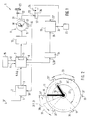
- appointment radio clock 1 also has, in particular, a radio receiver 2 with a demodulator 3, which is fed with radio frequency energy via an antenna 4, which is modulated every minute with binary-coded current time information 5.
- a radio receiver 2 with a demodulator 3, which is fed with radio frequency energy via an antenna 4, which is modulated every minute with binary-coded current time information 5.
- the current time information 5 contained therein is compared in a control circuit 7 with a display information 8 from the display device 9, given by the momentary position of pointers 10 in front of a dial 11. They are driven by an electromechanical converter 12.
- an output stage 13 for operating the converter 12 is operated at high speed f2, for example from a time-keeping circuit 15, until the current display information 8 of a display detector 16 ( preferably realized as a light barrier query of the pointer mechanism), the correct position of the pointers 10 with respect to the current time information 5 is determined.
- the control circuit 7 can switch the output stage 13 to time-keeping operation from the oscillator circuit 15, and the pointers 10 are moved with the frequency f1 at the correct time.
- the registers in the control circuit 7, which are set by the time information signal sequence 6 and are now clocked further from the time-keeping circuit 15, have the effect that the radio receiver 2 does not remain in operation for any length of time, in particular in the case of a battery-operated appointment radio clock 1, but in circuit-technically predetermined time cycles for the pointer position control and, if necessary, correction is switched on again, as illustrated by the control information 18 in FIG. 1.
- the appointment radio clock 1 is also equipped with an electronic coincidence circuit 19, which can be implemented in the context of a processor, which in particular also performs the function of the control circuit 7.
- a manually operated input device 20 allows the desired signaling time to be set, which is indicated, for example, by the position of an alarm time pointer 27 in front of the dial 11.
- a scanner 21 (constructed, for example, as the classic alarm mechanism, as an angle code scanner or else as a sensor similar to the display detector 16) delivers a switch-on signal 22 when the position of the pointer mechanism corresponds to the angular position of the alarm time pointer 27 set for the time of the alarm.
- the signal transmitter 23 is not yet triggered by an alarm signal 24 as a result of this alone.
- the function of the scanning device 21 includes a certain switching cycle 30 of typically plus / minus two minutes around a predetermined signaling time 31.
- the signaling times 31 ' are functionally permitted, for example due to a correspondingly designed latching coupling 32 in the operative connection of the manual input device 20.
- These are expediently offset from one another by a periodic setting grid 33, which is larger than the sampling switching cycle 30 and, in the given example, is expediently ten minutes in relation to the full hour.
- this setting raster 33 is greater than the period of one revolution of the alarm time pointer 27 minus the switching cycle 30, then it is ensured that within the period of the switching cycle 30 there may be a single signaling time 31 ', as can be seen in FIG 2 results without further ado.
- the alarm time pointer 27 is adjusted in front of the dial 11 with respect to the scanning device 21 such that the scanned signaling time 31, including the half switching response 30 (short) before the one, is included nominal signaling point in time 31 ', then shortly before this point in time 31' only the switch-on signal 22 appears.
- an interval and pulse generator 34 fed from the register of the control circuit 7 delivers a signaling signal.
- the switch-on signal supplied via it is typically present for between thirty and forty-five minutes until the scanning contact paths open again in the course of the further rotation of the pointer mechanism which is queried by the gear mechanism.
- the duration of the alarm signal 24 is expediently limited (in particular in order to avoid a permanent load on the electrical power source of a wireless clock 1 operated by a network) by the duration of the enable signal 35, in which, when it disappears, the coincidence condition of the circuit 19 again goes out.
- the interval and pulse generator 34 is therefore not only designed to switch through in the fixed rhythm of the adjustment grid 33 also implemented on the coupling 32; in addition, it contains a monostable characteristic based, for example, on a counting basis, in order to limit the output signal 35 in time.
- a flip-flop 36 can also be provided in front of or behind the coincidence circuit 19, which cancels out this coincidence condition a circuit-specific time period after the coincidence-related alarm signal 24 is inserted, or blocks the forwarding of the output alarm signal 24.
- this bistable flip-flop 36 has a set input 37 that is dynamically responsive to the onset of the control information, then the flip-flop 36 reset with a time delay from the alarm signal 24 can only be set again in preparation for the coincidence condition when the switch-on signal triggered by the pointer scanning device 21 is activated 22 after the corresponding continuation of the pointer 10 has ended and then reappears when an alarm time setting is reached again.
Landscapes
- Physics & Mathematics (AREA)
- General Physics & Mathematics (AREA)
- Electric Clocks (AREA)
- Electromechanical Clocks (AREA)
Claims (5)
- Réveil comportant un dispositif de palpage (21) mécanique de son aiguille de l'heure d'alarme (27), réagissant juste avant l'heure de délivrance du signal (31) sélectionnée, en vue de déclencher un signal d'enclenchement (22, 22′) pour un signal d'alarme (24), qui n'est effectivement enclenché ensuite que lorsque l'heure de délivrance du signal (31) est atteinte plus précisément, caractérisé en ce que le réveil est équipé comme une horloge radio (1), c'est-à-dire qu'il fournit une information de temps (5) corrigée par radio, ce réveil permettant de sélectionner au moyen de son aiguille de l'heure d'alarme (27) des heures de délivrance de signal (31′) successives, qui sont plus éloignées les unes des autres que l'intervalle de temps du jeu de manoeuvre (30) caractéristique du dispositif de palpage (21), et en ce que ce dispositif de palpage (21) déclenche en avance le signal d'enclenchement (22, 22′) d'au moins chaque fois cet intervalle de temps de son jeu de manoeuvre (30) caractéristique par rapport à l'heure délivrance de signal (31′), indiquée par l'aiguille de l'heure d'alarme (27), après quoi le signal d'enclenchement (22, 22′) n'est commandé pour la délivrance du signal d'alarme (24) que s'il y a coïncidence entre l'heure de délivrance de signal (31′), réglée au moyen de l'aiguille de l'heure d'alarme (27) et l'obtention effective de cette information de temps.
- Horloge radio de réveil selon la revendication 1, caractérisée en ce qu'il est prévu une bascule de remise à zéro (36) pour mettre fin au signal d'alarme (24) délivré.
- Horloge radio de réveil selon la revendication 1, caractérisée en ce qu'il est prévu un capteur (34) pour la délimitation dans le temps de la coïncidence sur la longueur du signal d'autorisation (35).
- Horloge radio de réveil selon l'une des revendications précédentes, caractérisée en ce qu'il est prévu un accouplement d'encliquetage (32) pour ne permettre le réglage de l'heure d'alarme que dans la grille de réglage (33).
- Horloge radio de réveil selon l'une des revendications précédentes, caractérisée en ce qu'il est prévu une bascule (36) qui ne délivre un signal d'enclenchement (22, 22′), fourni par le dispositif de palpage (21) que lorsque se produit à nouveau un signal d'enclenchement (22) après la fin du signal d'alarme (24) déclenché auparavant pour l'interrogation de coïncidence avec un autre signal d'autorisation (35).
Applications Claiming Priority (2)
| Application Number | Priority Date | Filing Date | Title |
|---|---|---|---|
| DE9010225U DE9010225U1 (de) | 1990-07-05 | 1990-07-05 | Termin-Funkuhr |
| DE9010225U | 1990-07-05 |
Publications (3)
| Publication Number | Publication Date |
|---|---|
| EP0464760A2 EP0464760A2 (fr) | 1992-01-08 |
| EP0464760A3 EP0464760A3 (en) | 1992-01-22 |
| EP0464760B1 true EP0464760B1 (fr) | 1994-09-28 |
Family
ID=6855332
Family Applications (1)
| Application Number | Title | Priority Date | Filing Date |
|---|---|---|---|
| EP91110912A Expired - Lifetime EP0464760B1 (fr) | 1990-07-05 | 1991-07-02 | Montre calendrier mise à l'heure par radio |
Country Status (4)
| Country | Link |
|---|---|
| EP (1) | EP0464760B1 (fr) |
| DE (2) | DE9010225U1 (fr) |
| ES (1) | ES2064010T3 (fr) |
| HK (1) | HK94595A (fr) |
Citations (3)
| Publication number | Priority date | Publication date | Assignee | Title |
|---|---|---|---|---|
| DE902836C (de) * | 1949-09-17 | 1954-01-28 | E H Helmut Junghans Dr Ing | Zeitmesser mit Ausloesung, insbesondere Weckeruhr |
| US3745761A (en) * | 1971-02-18 | 1973-07-17 | Suwa Seikosha Kk | Electronic timepiece having alarm means |
| US4148181A (en) * | 1976-03-10 | 1979-04-10 | Kieninger & Obergfell, Fabrik Fur Technische Laufwerke Und Apparate | System for controlling the striking mechanism of a timepiece |
Family Cites Families (1)
| Publication number | Priority date | Publication date | Assignee | Title |
|---|---|---|---|---|
| DE3510636C3 (de) * | 1985-03-23 | 1997-06-05 | Junghans Gmbh Geb | Autonome Funkuhr mit Zeitpunkt-Signalgeber |
-
1990
- 1990-07-05 DE DE9010225U patent/DE9010225U1/de not_active Expired - Lifetime
-
1991
- 1991-07-02 DE DE59103084T patent/DE59103084D1/de not_active Expired - Fee Related
- 1991-07-02 ES ES91110912T patent/ES2064010T3/es not_active Expired - Lifetime
- 1991-07-02 EP EP91110912A patent/EP0464760B1/fr not_active Expired - Lifetime
-
1995
- 1995-06-15 HK HK94595A patent/HK94595A/xx not_active IP Right Cessation
Patent Citations (3)
| Publication number | Priority date | Publication date | Assignee | Title |
|---|---|---|---|---|
| DE902836C (de) * | 1949-09-17 | 1954-01-28 | E H Helmut Junghans Dr Ing | Zeitmesser mit Ausloesung, insbesondere Weckeruhr |
| US3745761A (en) * | 1971-02-18 | 1973-07-17 | Suwa Seikosha Kk | Electronic timepiece having alarm means |
| US4148181A (en) * | 1976-03-10 | 1979-04-10 | Kieninger & Obergfell, Fabrik Fur Technische Laufwerke Und Apparate | System for controlling the striking mechanism of a timepiece |
Also Published As
| Publication number | Publication date |
|---|---|
| DE59103084D1 (de) | 1994-11-03 |
| EP0464760A2 (fr) | 1992-01-08 |
| EP0464760A3 (en) | 1992-01-22 |
| DE9010225U1 (de) | 1991-11-07 |
| HK94595A (en) | 1995-06-23 |
| ES2064010T3 (es) | 1995-01-16 |
Similar Documents
| Publication | Publication Date | Title |
|---|---|---|
| EP0529390B1 (fr) | Dispositif de détection de la position du rouage avec de correction | |
| EP0308881B1 (fr) | Montre commandée par radio | |
| EP0374745B2 (fr) | Montre radioréceptrice autonome | |
| DE2521698C3 (de) | Elektronische Uhr, insbesondere elektronische Armbanduhr | |
| EP0042913A2 (fr) | Procédé pour la remise à l'heure d'une horloge commandée par radio à l'aide de signaux horaires | |
| CH618763A5 (fr) | ||
| CH686648B5 (de) | Alarmeinstellmechanismus fuer einen analogen Zeitmesser. | |
| EP0667004B1 (fr) | Mouvement d'horlogerie radiocommande | |
| DE69015468T2 (de) | Zeitmessvorrichtung. | |
| EP0464760B1 (fr) | Montre calendrier mise à l'heure par radio | |
| DE3510636C3 (de) | Autonome Funkuhr mit Zeitpunkt-Signalgeber | |
| EP0513633B1 (fr) | Montre réveil | |
| DE2809796C2 (fr) | ||
| EP0423576B1 (fr) | Montre agenda électromécanique | |
| EP0553722A2 (fr) | Petite montre-radio autonome à affichage autonome, en particulier montre radio bracelet | |
| DE2609871C2 (de) | Elektrisches Schlagwerk | |
| EP0664496B1 (fr) | Montre à affichage de temps commutable, en particulier réveil commandé par radio à affichage digital de temps d'alarme | |
| DE10159010B4 (de) | Elektromechanische Schaltuhr | |
| DE8916114U1 (de) | Elektromechanische Terminuhr | |
| DE2113233C3 (de) | Zeithaltendes Gerät | |
| EP0389987B1 (fr) | Dispositif de commande pour affichage numérique | |
| DE2301988C3 (de) | Zeitgebermechanismus für eine Uhr o.dgl | |
| DE2545814A1 (de) | Weckeruhr | |
| DE3009306A1 (de) | Elektronisches zeitschaltwerk | |
| DD300796A7 (de) | Kontaktmechanismus für Schaltuhren |
Legal Events
| Date | Code | Title | Description |
|---|---|---|---|
| PUAI | Public reference made under article 153(3) epc to a published international application that has entered the european phase |
Free format text: ORIGINAL CODE: 0009012 |
|
| PUAL | Search report despatched |
Free format text: ORIGINAL CODE: 0009013 |
|
| AK | Designated contracting states |
Kind code of ref document: A2 Designated state(s): CH DE ES FR GB IT LI |
|
| AK | Designated contracting states |
Kind code of ref document: A3 Designated state(s): CH DE ES FR GB IT LI |
|
| 17P | Request for examination filed |
Effective date: 19920208 |
|
| 17Q | First examination report despatched |
Effective date: 19930827 |
|
| GRAA | (expected) grant |
Free format text: ORIGINAL CODE: 0009210 |
|
| AK | Designated contracting states |
Kind code of ref document: B1 Designated state(s): CH DE ES FR GB IT LI |
|
| REF | Corresponds to: |
Ref document number: 59103084 Country of ref document: DE Date of ref document: 19941103 |
|
| ITF | It: translation for a ep patent filed | ||
| GBT | Gb: translation of ep patent filed (gb section 77(6)(a)/1977) |
Effective date: 19941201 |
|
| REG | Reference to a national code |
Ref country code: ES Ref legal event code: FG2A Ref document number: 2064010 Country of ref document: ES Kind code of ref document: T3 |
|
| ET | Fr: translation filed | ||
| PLBI | Opposition filed |
Free format text: ORIGINAL CODE: 0009260 |
|
| 26 | Opposition filed |
Opponent name: ETA SA FABRIQUES D'EBAUCHES Effective date: 19950515 |
|
| PLBF | Reply of patent proprietor to notice(s) of opposition |
Free format text: ORIGINAL CODE: EPIDOS OBSO |
|
| PLBO | Opposition rejected |
Free format text: ORIGINAL CODE: EPIDOS REJO |
|
| APAC | Appeal dossier modified |
Free format text: ORIGINAL CODE: EPIDOS NOAPO |
|
| APAE | Appeal reference modified |
Free format text: ORIGINAL CODE: EPIDOS REFNO |
|
| PGFP | Annual fee paid to national office [announced via postgrant information from national office to epo] |
Ref country code: FR Payment date: 19980528 Year of fee payment: 8 |
|
| PGFP | Annual fee paid to national office [announced via postgrant information from national office to epo] |
Ref country code: CH Payment date: 19980616 Year of fee payment: 8 |
|
| PGFP | Annual fee paid to national office [announced via postgrant information from national office to epo] |
Ref country code: GB Payment date: 19980629 Year of fee payment: 8 |
|
| PGFP | Annual fee paid to national office [announced via postgrant information from national office to epo] |
Ref country code: ES Payment date: 19980707 Year of fee payment: 8 |
|
| PLBQ | Unpublished change to opponent data |
Free format text: ORIGINAL CODE: EPIDOS OPPO |
|
| PLAB | Opposition data, opponent's data or that of the opponent's representative modified |
Free format text: ORIGINAL CODE: 0009299OPPO |
|
| APAC | Appeal dossier modified |
Free format text: ORIGINAL CODE: EPIDOS NOAPO |
|
| R26 | Opposition filed (corrected) |
Opponent name: ETA SA FABRIQUES D'EBAUCHES Effective date: 19950515 |
|
| PG25 | Lapsed in a contracting state [announced via postgrant information from national office to epo] |
Ref country code: GB Free format text: LAPSE BECAUSE OF NON-PAYMENT OF DUE FEES Effective date: 19990702 |
|
| PG25 | Lapsed in a contracting state [announced via postgrant information from national office to epo] |
Ref country code: ES Free format text: LAPSE BECAUSE OF NON-PAYMENT OF DUE FEES Effective date: 19990703 |
|
| PG25 | Lapsed in a contracting state [announced via postgrant information from national office to epo] |
Ref country code: LI Free format text: LAPSE BECAUSE OF NON-PAYMENT OF DUE FEES Effective date: 19990731 Ref country code: FR Free format text: THE PATENT HAS BEEN ANNULLED BY A DECISION OF A NATIONAL AUTHORITY Effective date: 19990731 Ref country code: CH Free format text: LAPSE BECAUSE OF NON-PAYMENT OF DUE FEES Effective date: 19990731 |
|
| GBPC | Gb: european patent ceased through non-payment of renewal fee |
Effective date: 19990702 |
|
| REG | Reference to a national code |
Ref country code: CH Ref legal event code: PL |
|
| REG | Reference to a national code |
Ref country code: FR Ref legal event code: ST |
|
| PLBN | Opposition rejected |
Free format text: ORIGINAL CODE: 0009273 |
|
| STAA | Information on the status of an ep patent application or granted ep patent |
Free format text: STATUS: OPPOSITION REJECTED |
|
| 27O | Opposition rejected |
Effective date: 19990326 |
|
| REG | Reference to a national code |
Ref country code: ES Ref legal event code: FD2A Effective date: 20000810 |
|
| PG25 | Lapsed in a contracting state [announced via postgrant information from national office to epo] |
Ref country code: IT Free format text: LAPSE BECAUSE OF NON-PAYMENT OF DUE FEES;WARNING: LAPSES OF ITALIAN PATENTS WITH EFFECTIVE DATE BEFORE 2007 MAY HAVE OCCURRED AT ANY TIME BEFORE 2007. THE CORRECT EFFECTIVE DATE MAY BE DIFFERENT FROM THE ONE RECORDED. Effective date: 20050702 |
|
| PGFP | Annual fee paid to national office [announced via postgrant information from national office to epo] |
Ref country code: DE Payment date: 20050928 Year of fee payment: 15 |
|
| APAH | Appeal reference modified |
Free format text: ORIGINAL CODE: EPIDOSCREFNO |
|
| PG25 | Lapsed in a contracting state [announced via postgrant information from national office to epo] |
Ref country code: DE Free format text: LAPSE BECAUSE OF NON-PAYMENT OF DUE FEES Effective date: 20070201 |