EP0464796A1 - Riementrieb einer Brennkraftmaschine - Google Patents
Riementrieb einer Brennkraftmaschine Download PDFInfo
- Publication number
- EP0464796A1 EP0464796A1 EP91111034A EP91111034A EP0464796A1 EP 0464796 A1 EP0464796 A1 EP 0464796A1 EP 91111034 A EP91111034 A EP 91111034A EP 91111034 A EP91111034 A EP 91111034A EP 0464796 A1 EP0464796 A1 EP 0464796A1
- Authority
- EP
- European Patent Office
- Prior art keywords
- combustion engine
- belt
- belt drive
- cooling
- cooling fan
- Prior art date
- Legal status (The legal status is an assumption and is not a legal conclusion. Google has not performed a legal analysis and makes no representation as to the accuracy of the status listed.)
- Granted
Links
- 238000002485 combustion reaction Methods 0.000 title claims abstract description 18
- 238000001816 cooling Methods 0.000 claims abstract description 44
- 239000002775 capsule Substances 0.000 claims description 6
- 238000002347 injection Methods 0.000 description 3
- 239000007924 injection Substances 0.000 description 3
- 238000004519 manufacturing process Methods 0.000 description 2
- 238000004512 die casting Methods 0.000 description 1
- 238000000034 method Methods 0.000 description 1
- 239000002918 waste heat Substances 0.000 description 1
Images

Classifications
-
- F—MECHANICAL ENGINEERING; LIGHTING; HEATING; WEAPONS; BLASTING
- F01—MACHINES OR ENGINES IN GENERAL; ENGINE PLANTS IN GENERAL; STEAM ENGINES
- F01P—COOLING OF MACHINES OR ENGINES IN GENERAL; COOLING OF INTERNAL-COMBUSTION ENGINES
- F01P11/00—Component parts, details, or accessories not provided for in, or of interest apart from, groups F01P1/00 - F01P9/00
- F01P11/12—Filtering, cooling, or silencing cooling-air
-
- F—MECHANICAL ENGINEERING; LIGHTING; HEATING; WEAPONS; BLASTING
- F01—MACHINES OR ENGINES IN GENERAL; ENGINE PLANTS IN GENERAL; STEAM ENGINES
- F01P—COOLING OF MACHINES OR ENGINES IN GENERAL; COOLING OF INTERNAL-COMBUSTION ENGINES
- F01P1/00—Air cooling
- F01P1/06—Arrangements for cooling other engine or machine parts
-
- F—MECHANICAL ENGINEERING; LIGHTING; HEATING; WEAPONS; BLASTING
- F01—MACHINES OR ENGINES IN GENERAL; ENGINE PLANTS IN GENERAL; STEAM ENGINES
- F01P—COOLING OF MACHINES OR ENGINES IN GENERAL; COOLING OF INTERNAL-COMBUSTION ENGINES
- F01P5/00—Pumping cooling-air or liquid coolants
- F01P5/02—Pumping cooling-air; Arrangements of cooling-air pumps, e.g. fans or blowers
- F01P5/04—Pump-driving arrangements
-
- Y—GENERAL TAGGING OF NEW TECHNOLOGICAL DEVELOPMENTS; GENERAL TAGGING OF CROSS-SECTIONAL TECHNOLOGIES SPANNING OVER SEVERAL SECTIONS OF THE IPC; TECHNICAL SUBJECTS COVERED BY FORMER USPC CROSS-REFERENCE ART COLLECTIONS [XRACs] AND DIGESTS
- Y10—TECHNICAL SUBJECTS COVERED BY FORMER USPC
- Y10T—TECHNICAL SUBJECTS COVERED BY FORMER US CLASSIFICATION
- Y10T74/00—Machine element or mechanism
- Y10T74/21—Elements
- Y10T74/2186—Gear casings
- Y10T74/2189—Cooling
Definitions
- the invention relates to an encapsulated belt drive of an internal combustion engine according to the preamble of patent claim 1.
- Such an encapsulated belt drive is known from DE-PS 94 82 07.
- a cooling air flow branched off from the cooling fan behind the first cylinder is introduced into the belt capsule via a connecting line and a filter device.
- the cooling air flow is only branched off behind the first cylinder, since the cooling air flow is already heated at this point by the waste heat absorbed by the first cylinder and the full cooling capacity for cooling the belt drive is therefore no longer available.
- This type of cooling air flow also contributes to an unfavorable cooling of the cylinders, since the first cylinder is cooled particularly intensively and the subsequent cylinders are cooled with a cooling air quantity reduced by the branched cooling air flow.
- the connecting line as a cantilever line, is susceptible to damage from external inlets and vibrations of the internal combustion engine and, due to its large space requirement, defines the upper internal combustion engine contour.
- the invention is based on the object of providing an encapsulated belt drive of an internal combustion engine which, on the one hand, ensures effective cooling of the belt drive without disadvantageous cooling of the cylinders and, on the other hand, is arranged in a space-saving manner and not susceptible to damage.
- the connecting line is designed as an air shaft which is formed in the area of the cooling fan by a cooling fan jacket flange and a portion of the adjacent cylinder head and continues via a housing part which is sealingly connected to the cooling fan jacket flange and which connects to an air inlet opening of the belt capsule .
- the filter device is formed by two baffles, which are arranged in the cooling air fan jacket flange and in the housing part.
- the baffles can be cast or molded onto the respective components, so that the manufacturing effort is very low.
- the housing part is made of plastic and is therefore easy and uncomplicated to manufacture with low weight.
- This dust-free and effective cooling can be used in particular in the case of a toothed belt which drives, for example, a camshaft or injection pump of a self-igniting internal combustion engine.
- a second air shaft is arranged next to the first for supplying cooling air to a second belt.
- This second belt is preferably in turn a toothed belt, which, however, drives auxiliary units such as hydraulic pumps. Effective cooling of the toothed belt is essential, especially when almost the entire useful output of an internal combustion engine is used to drive hydraulic pumps.
- the second air shaft is constructed largely the same as the first air shaft and in particular it is provided to provide a two-pass, one-piece housing part for the transport of cooling air.
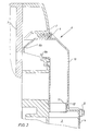
- a self-igniting internal combustion engine (not shown further) has a cooling air blower 1 which is used for cooling components of the internal combustion engine and / or a heat exchanger or the medium located therein.
- the cooling air blower 1 is enclosed by a cooling blower jacket which has a cooling blower jacket flange 2.
- the internal combustion engine has a crankshaft which converts the translational movement generated by the pistons of the internal combustion engine into a rotary movement.
- At least one toothed belt wheel 3 is fastened to the front end of the crankshaft, which drives the camshaft of the internal combustion engine or, at the same time, the injection pump or the injection pump elements via a toothed belt.
- the toothed belt wheel 3 and the toothed belt are covered by a belt capsule 4, which is fastened to the internal combustion engine by means of screws 5.
- the connecting line is designed as an air shaft 6, which is in the area of the cooling fan 1 from the cooling fan jacket flange 2 and a partial section of the adjacent cylinder head 7 is formed.
- a first rib in the form of a baffle 8a is cast onto the cooling fan jacket flange 2 produced by the die casting process.
- a housing part 10, which forms the further air shaft, is fastened to the cooling fan jacket flange 2 by a screw connection 9.
- the housing part 10 has a chicane 8b in the area of the screw connection 9, which is molded onto the housing part 10.
- the housing part 10 has a constriction 11 which engages in a cooling air inlet opening 12 of the belt capsule 4.
Landscapes
- Engineering & Computer Science (AREA)
- Chemical & Material Sciences (AREA)
- Combustion & Propulsion (AREA)
- Mechanical Engineering (AREA)
- General Engineering & Computer Science (AREA)
- Cylinder Crankcases Of Internal Combustion Engines (AREA)
Abstract
Description
- Die Erfindung betrifft einen gekapselten Riementrieb einer Brennkraftmaschine gemäß Oberbegriff des Patentanspruchs 1.
- Ein derartiger gekapselter Riementrieb ist aus der DE-PS 94 82 07 bekannt. Bei diesem Riementrieb wird ein von dem Kühlgebläse hinter dem ersten Zylinder abgezweigter Kühlluftstrom über eine Verbindungsleitung und eine Filtereinrichtung in die Riemenkapsel eingeleitet. Nachteilig ist, daß der Kühlluftstrom erst hinter dem ersten Zylinder abgezweigt wird, da der Kühlluftstrom an dieser Stelle schon um die von dem ersten Zylinder aufgenommene Abwärme erhitzt ist und somit nicht mehr die volle Kühlleistung zur Kühlung des Riementriebs zur Verfügung steht. Auch trägt diese Art der Kühlluftstromentnahme zu einer ungünstigen Kühlung der Zylinder bei, da der erste Zylinder besonders intensiv gekühlt wird und die nachfolgenden Zylinder mit einer um den abgezweigten Kühlluftstrom verringerten Kühlluftmenge gekühlt werden. Weiterhin ist die Verbindungsleitung als freitragende Leitung anfällig gegen Beschädigungen durch äußere Einlfüsse und durch Vibrationen der Brennkraftmaschine und legt durch ihren großen Platzbedarf die obere Brennkraftmaschinenkontur fest.
- Der Erfindung liegt die Aufgabe zugrunde, einen gekapselten Riementrieb einer Brennkraftmaschine bereitzustellen, der einerseits für eine effektive Kühlung des Riementriebs ohne Benachteiligung der Kühlung der Zylinder sorgt und andererseits raumsparend und unanfällig gegen Beschädigungen angeordnet ist.
- Diese Aufgabe wird erfindungsgemäß dadurch gelöst, daß die Verbindungsleitung als Luftschacht ausgebildet ist, der im Bereich des Kühlgebläses von einem Kühlgebläsemantelflansch und einem Teilabschnitt des angrenzenden Zylinderkopfes gebildet wird und sich über ein dichtend mit dem Kühlgebläsemantelflansch verbundenes Gehäuseteil fortsetzt, daß an eine Lufteinlaßöffnung der Riemenkapsel anschließt. Damit werden die zuvor geschilderten Nachteile vermieden und zudem eine einfach aufgebaute Verbindungsleitung ermöglicht. Die Gefahr von Beschädigungen ist durch die integrierte Anordnung der Verbindungsleitung sehr gering. Durch die direkte Entnahme des Kühlluftstromes im Bereich des Kühlgebläses ist die Kühlluft noch nicht erwärmt und bei der Zylinderkühlung treten keine Kühlluftmengenunterschiede auf.
- In Weiterbildung der Erfindung wird die Filtereinrichtung durch zwei Schikanen gebildet, die im Kühlluftgebläsemantelflansch und in dem Gehäuseteil angeordnet sind. Dabei können die Schikanen an die jeweiligen Bauteile angegossen bzw. angespritzt sein, so daß der Herstellungsaufwand sehr gering ist.
- Erfindungsgemäß ist das Gehäuseteil aus Kunststoff gefertigt und ist somit leicht und unkompliziert bei geringen Gewicht herstellbar.
- Diese staubfreie und effektive Kühlung ist insbesondere bei einem Zahnriemen, der beispielsweise eine Nockenwelle oder Einspritzpumpe einer selbstzündenden Brennkraftmaschine antreibt, einsetzbar.
- In Weiterbildung der Erfindung ist ein zweiter Luftschacht neben dem ersten zur Kühlluftversorgung eines zweiten Riemens angeordnet. Dieser zweite Riemen ist vorzugsweise wiederrum ein Zahnriemen, der aber Hilfsaggregate wie beispielsweise Hydraulikpumpen antreibt. Gerade, wenn nahezu die gesamte Nutzleistung einer Brennkraftmaschine zum Antrieb von Hydraulikpumpen genutzt wird, ist eine effektive Kühlung des Zahnriemens unumgänglich. Der zweite Luftschacht ist dabei weitestgehend gleich aufgebaut wie der erste Luftschacht und insbesondere ist vorgesehen, ein zweizügiges, einteiliges Gehäuseteil zum Kühllufttransport vorzusehen.
- Weitere Vorteile der Erfindung sind der Zeichnungsbeschreibung zu entnehmen, in der ein in den Figuren dargestelltes Ausführungsbeispiel der Erfindung beschrieben ist.
- Es zeigen:
- Fig.1: eine Draufsicht auf eine Verbindungsleitung,
- Fig.2: einen Querschnitt durch die Verbindungsleitung.
- Eine nicht weiter dargestellte selbstzündende Brennkraftmaschine weist ein Kühlluftgebläse 1 auf, das zur Kühlung von Bauteilen der Brennkraftmaschine und/oder eines Wärmetauschers bzw. des darin befindlichen Mediums genutzt wird. Das Kühlluftgebläse 1 ist von einem Kühlgebläsemantel eingefasst, der einen Kühlgebläsemantelflansch 2 aufweist. Die Brennkraftmaschine weist eine Kurbelwelle auf, die die von den Kolben der Brennkraftmaschine erzeugte translatorische in eine rotatorische Bewegung umsetzt. Dabei ist auf dem stirnseitigen Ende der Kurbelwelle zumindest ein Zahnriemenrad 3 befestigt, das über einen Zahnriemen die Nockenwelle der Brennkraftmaschine bzw. gleichzeitig der Einspritzpumpe oder der Einspritzpumpenelemente antreibt. Dabei wird das Zahnriemenrad 3 und der Zahnriemen von einer Riemenkapsel 4 abgedeckt, die mittels Schrauben 5 an der Brennkraftmaschine befestigt ist. Die Verbindungsleitung ist als Luftschacht 6 ausgebildet, der im Bereich des Kühlgebläses 1 von dem Kühlgebläsemantelflansch 2 und einem Teilabschnitt des angrenzenden Zylinderkopfes 7 gebildet wird. Dabei ist an den im Druckgußverfahren hergestellten Kühlgebläsemantelflansch 2 eine erste Rippe in Form einer Schikane 8a angegossen. An dem Kühlgebläsemantelflansch 2 ist durch eine Schraubverbindung 9 ein Gehäuseteil 10 befestigt, das den weiteren Luftschaft bildet. Das Gehäuseteil 10 weist im Bereich der Schraubverbindung 9 eine Schikane 8b auf, die an das Gehäuseteil 10 angespritzt ist. An dem gegenüberliegenden Ende weist das Gehäuseteil 10 eine Verengung 11 auf, die in eine Kühllufteinlaßöffnung 12 der Riemenkapsel 4 eingreift.
Claims (5)
Priority Applications (1)
| Application Number | Priority Date | Filing Date | Title |
|---|---|---|---|
| DE59103085T DE59103085D1 (de) | 1991-07-03 | 1991-07-03 | Riementrieb einer Brennkraftmaschine. |
Applications Claiming Priority (1)
| Application Number | Priority Date | Filing Date | Title |
|---|---|---|---|
| DE4021175A DE4021175A1 (de) | 1990-07-03 | 1990-07-03 | Riementrieb einer brennkraftmaschine |
Publications (2)
| Publication Number | Publication Date |
|---|---|
| EP0464796A1 true EP0464796A1 (de) | 1992-01-08 |
| EP0464796B1 EP0464796B1 (de) | 1994-09-28 |
Family
ID=6409574
Family Applications (1)
| Application Number | Title | Priority Date | Filing Date |
|---|---|---|---|
| EP91111034A Expired - Lifetime EP0464796B1 (de) | 1990-07-03 | 1991-07-03 | Riementrieb einer Brennkraftmaschine |
Country Status (3)
| Country | Link |
|---|---|
| US (1) | US5277663A (de) |
| EP (1) | EP0464796B1 (de) |
| DE (1) | DE4021175A1 (de) |
Families Citing this family (4)
| Publication number | Priority date | Publication date | Assignee | Title |
|---|---|---|---|---|
| DE4136748A1 (de) * | 1991-11-08 | 1993-05-13 | Kloeckner Humboldt Deutz Ag | Fluessigkeitsgekuehlte brennkraftmaschine |
| DE19517491A1 (de) * | 1995-05-12 | 1996-11-14 | Zahnradfabrik Friedrichshafen | Kühlung für eine Getriebesteuerung |
| US5957796A (en) * | 1998-03-19 | 1999-09-28 | Mclean; Vernon | Belt guard |
| US20250003434A1 (en) * | 2023-06-27 | 2025-01-02 | Dana Automotive Systems Group, Llc | Plastic vent with a flow disruptor |
Citations (4)
| Publication number | Priority date | Publication date | Assignee | Title |
|---|---|---|---|---|
| DE1236276B (de) * | 1965-11-09 | 1967-03-09 | Porsche Kg | Antrieb der Hilfsaggregate an Brennkraft-maschinen, insbesondere fuer Kraftfahrzeuge |
| DE2265214A1 (de) * | 1972-05-08 | 1976-12-16 | Hatz Motoren | Brennkraftmaschine mit geraeuschdaempfung |
| US4497285A (en) * | 1981-09-09 | 1985-02-05 | Honda Giken Kogyo Kabushiki Kaisha | Cooling structure for internal combustion engine |
| DE3419368C1 (de) * | 1984-05-24 | 1985-05-09 | Daimler-Benz Ag, 7000 Stuttgart | Belueftungseinrichtung an einer Brennkraftmaschine |
Family Cites Families (11)
| Publication number | Priority date | Publication date | Assignee | Title |
|---|---|---|---|---|
| US2696074A (en) * | 1953-01-02 | 1954-12-07 | Gen Motors Corp | Combined torque converter and engine air-cooling system |
| DE948207C (de) * | 1953-08-05 | 1956-08-30 | Kloeckner Humboldt Deutz Ag | Riementrieb fuer Brennkraftmaschinen |
| DE1945777U (de) * | 1966-06-10 | 1966-09-08 | Kloeckner Humboldt Deutz Ag | Kuehleinrichtung an einer brennkraftkolbenmaschine. |
| IT984319B (it) * | 1972-05-08 | 1974-11-20 | Hatz Motoren | Macchina a combustione interna con insonorizzazione |
| US3926155A (en) * | 1972-05-08 | 1975-12-16 | Hatz Motoren | Internal combustion engine with silencing means |
| US4422498A (en) * | 1981-09-08 | 1983-12-27 | Yci Usa, Inc. | Machine tool cooling system |
| FR2533287B1 (fr) * | 1982-08-18 | 1988-04-01 | Honda Motor Co Ltd | Dispositif de transmission du type a courroie comprenant des moyens de ventilation montes sur une poulie |
| JPS5939920A (ja) * | 1982-08-30 | 1984-03-05 | Suzuki Motor Co Ltd | エンジンと駆動装置の冷却装置 |
| JPS61146694A (ja) * | 1984-12-19 | 1986-07-04 | 本田技研工業株式会社 | パワ−ユニツトの冷却装置 |
| US4697665A (en) * | 1985-06-18 | 1987-10-06 | Polaris Industries, Inc. | Recreational vehicle with air cooled transmission |
| DE3631517A1 (de) * | 1986-09-17 | 1988-04-14 | Konrad Dipl Ing Schmidt | Ein- oder mehrteilige schutzverkleidung fuer zugmittelgetriebe |
-
1990
- 1990-07-03 DE DE4021175A patent/DE4021175A1/de not_active Withdrawn
-
1991
- 1991-07-03 US US07/725,435 patent/US5277663A/en not_active Expired - Fee Related
- 1991-07-03 EP EP91111034A patent/EP0464796B1/de not_active Expired - Lifetime
Patent Citations (4)
| Publication number | Priority date | Publication date | Assignee | Title |
|---|---|---|---|---|
| DE1236276B (de) * | 1965-11-09 | 1967-03-09 | Porsche Kg | Antrieb der Hilfsaggregate an Brennkraft-maschinen, insbesondere fuer Kraftfahrzeuge |
| DE2265214A1 (de) * | 1972-05-08 | 1976-12-16 | Hatz Motoren | Brennkraftmaschine mit geraeuschdaempfung |
| US4497285A (en) * | 1981-09-09 | 1985-02-05 | Honda Giken Kogyo Kabushiki Kaisha | Cooling structure for internal combustion engine |
| DE3419368C1 (de) * | 1984-05-24 | 1985-05-09 | Daimler-Benz Ag, 7000 Stuttgart | Belueftungseinrichtung an einer Brennkraftmaschine |
Non-Patent Citations (1)
| Title |
|---|
| PATENT ABSTRACTS OF JAPAN vol. 8, no. 143 (M-306)(1580) 04 Juli 1984, & JP-A-59 39920 (SUZUKI JIDOSHA) 05 März 1984, * |
Also Published As
| Publication number | Publication date |
|---|---|
| EP0464796B1 (de) | 1994-09-28 |
| DE4021175A1 (de) | 1992-01-09 |
| US5277663A (en) | 1994-01-11 |
Similar Documents
| Publication | Publication Date | Title |
|---|---|---|
| DE3048449A1 (de) | Hilfsgeraeteaggregat fuer eine wassergekuehlte brennkraftmaschine | |
| DE69919583T2 (de) | Vorrichtung für eine brennkraftmaschine mit aufladung | |
| EP0807748A1 (de) | Brennkraftmaschine | |
| DE3044253A1 (de) | Brennkraftmaschine, insbesondere einreihige mehrzylinder-brennkraftmaschine | |
| DE102012206106A1 (de) | Anordnung eines Ladeluftkühlers in einem Ansaugrohr | |
| DE7707211U1 (de) | Fluessigkeitsgekuehlte brennkraftmaschine | |
| EP0711923B1 (de) | Elektrisch angetriebene Luftpumpe | |
| DE19535963B4 (de) | System zur Abnahme von Leistung aus einer Kurbelwelle | |
| DE3702028A1 (de) | Verbrennungsmotor mit wasserkuehlung | |
| DE4433247A1 (de) | Kombinationsgehäuse | |
| EP0464796B1 (de) | Riementrieb einer Brennkraftmaschine | |
| DE69427877T2 (de) | Viertakt-Brennkraftmaschine | |
| DE20121314U1 (de) | Kühler für den Motor eines Luftkompressors | |
| EP1045149A2 (de) | Kühlmittelpumpe | |
| DE19949322C1 (de) | Kühlgebläse, insbesondere Kühlerventilator für Kraftfahrzeuge | |
| DE19509002C2 (de) | Thermostatanbaupositionsstruktur | |
| EP0508188A2 (de) | Ansaugsystem für eine selbstzündende Brennkraftmaschine | |
| DE69112932T2 (de) | Verdichter. | |
| DE2553291A1 (de) | Gegossenes zylinder-kurbelgehaeuse fuer wassergekuehlte v-motoren | |
| DE2737054A1 (de) | Fluessigkeitsgekuehlte brennkraftmaschine mit einem pumpenbetriebenen schmieroelkreislauf | |
| EP0449129B1 (de) | Brennkraftmaschine | |
| DE68908376T2 (de) | Motorpumpenaggregat für einen Hochdruckreiniger. | |
| DE703823C (de) | Sternmotor mit einem Axialgeblaese fuer die Kuehlluft | |
| DE1232398B (de) | Luftgekuehlte Kolbenbrennkraftmaschine | |
| DE2722101C2 (de) | Gekapselte, wassergekühlte Brennkraftmaschine für Kraftfahrzeuge |
Legal Events
| Date | Code | Title | Description |
|---|---|---|---|
| PUAI | Public reference made under article 153(3) epc to a published international application that has entered the european phase |
Free format text: ORIGINAL CODE: 0009012 |
|
| AK | Designated contracting states |
Kind code of ref document: A1 Designated state(s): DE ES FR GB IT |
|
| RAP1 | Party data changed (applicant data changed or rights of an application transferred) |
Owner name: KLOECKNER-HUMBOLDT-DEUTZ AG |
|
| 17P | Request for examination filed |
Effective date: 19911211 |
|
| 17Q | First examination report despatched |
Effective date: 19930629 |
|
| GRAA | (expected) grant |
Free format text: ORIGINAL CODE: 0009210 |
|
| AK | Designated contracting states |
Kind code of ref document: B1 Designated state(s): DE ES FR GB IT |
|
| PG25 | Lapsed in a contracting state [announced via postgrant information from national office to epo] |
Ref country code: IT Free format text: LAPSE BECAUSE OF FAILURE TO SUBMIT A TRANSLATION OF THE DESCRIPTION OR TO PAY THE FEE WITHIN THE PRE;WARNING: LAPSES OF ITALIAN PATENTS WITH EFFECTIVE DATE BEFORE 2007 MAY HAVE OCCURRED AT ANY TIME BEFORE 2007. THE CORRECT EFFECTIVE DATE MAY BE DIFFERENT FROM THE ONE RECORDED.SCRIBED TIME-LIMIT Effective date: 19940928 Ref country code: ES Free format text: THE PATENT HAS BEEN ANNULLED BY A DECISION OF A NATIONAL AUTHORITY Effective date: 19940928 |
|
| REF | Corresponds to: |
Ref document number: 59103085 Country of ref document: DE Date of ref document: 19941103 |
|
| ET | Fr: translation filed | ||
| GBT | Gb: translation of ep patent filed (gb section 77(6)(a)/1977) |
Effective date: 19941118 |
|
| PLBE | No opposition filed within time limit |
Free format text: ORIGINAL CODE: 0009261 |
|
| STAA | Information on the status of an ep patent application or granted ep patent |
Free format text: STATUS: NO OPPOSITION FILED WITHIN TIME LIMIT |
|
| 26N | No opposition filed | ||
| REG | Reference to a national code |
Ref country code: FR Ref legal event code: CD |
|
| PGFP | Annual fee paid to national office [announced via postgrant information from national office to epo] |
Ref country code: FR Payment date: 20000621 Year of fee payment: 10 |
|
| PGFP | Annual fee paid to national office [announced via postgrant information from national office to epo] |
Ref country code: GB Payment date: 20000622 Year of fee payment: 10 |
|
| PGFP | Annual fee paid to national office [announced via postgrant information from national office to epo] |
Ref country code: DE Payment date: 20000726 Year of fee payment: 10 |
|
| PG25 | Lapsed in a contracting state [announced via postgrant information from national office to epo] |
Ref country code: GB Free format text: LAPSE BECAUSE OF NON-PAYMENT OF DUE FEES Effective date: 20010703 |
|
| GBPC | Gb: european patent ceased through non-payment of renewal fee |
Effective date: 20010703 |
|
| PG25 | Lapsed in a contracting state [announced via postgrant information from national office to epo] |
Ref country code: FR Free format text: LAPSE BECAUSE OF NON-PAYMENT OF DUE FEES Effective date: 20020329 |
|
| PG25 | Lapsed in a contracting state [announced via postgrant information from national office to epo] |
Ref country code: DE Free format text: LAPSE BECAUSE OF NON-PAYMENT OF DUE FEES Effective date: 20020501 |
|
| REG | Reference to a national code |
Ref country code: FR Ref legal event code: ST |