EP0464879B1 - Vorrichtung zur Trennung des Luminanzsignals und des Chrominanzsignals und Verfahren - Google Patents
Vorrichtung zur Trennung des Luminanzsignals und des Chrominanzsignals und Verfahren Download PDFInfo
- Publication number
- EP0464879B1 EP0464879B1 EP91201213A EP91201213A EP0464879B1 EP 0464879 B1 EP0464879 B1 EP 0464879B1 EP 91201213 A EP91201213 A EP 91201213A EP 91201213 A EP91201213 A EP 91201213A EP 0464879 B1 EP0464879 B1 EP 0464879B1
- Authority
- EP
- European Patent Office
- Prior art keywords
- signal
- chrominance
- delaying
- chrominance signal
- band pass
- Prior art date
- Legal status (The legal status is an assumption and is not a legal conclusion. Google has not performed a legal analysis and makes no representation as to the accuracy of the status listed.)
- Expired - Lifetime
Links
Images



Classifications
-
- H—ELECTRICITY
- H04—ELECTRIC COMMUNICATION TECHNIQUE
- H04N—PICTORIAL COMMUNICATION, e.g. TELEVISION
- H04N9/00—Details of colour television systems
- H04N9/77—Circuits for processing the brightness signal and the chrominance signal relative to each other, e.g. adjusting the phase of the brightness signal relative to the colour signal, correcting differential gain or differential phase
-
- H—ELECTRICITY
- H04—ELECTRIC COMMUNICATION TECHNIQUE
- H04N—PICTORIAL COMMUNICATION, e.g. TELEVISION
- H04N9/00—Details of colour television systems
- H04N9/77—Circuits for processing the brightness signal and the chrominance signal relative to each other, e.g. adjusting the phase of the brightness signal relative to the colour signal, correcting differential gain or differential phase
- H04N9/78—Circuits for processing the brightness signal and the chrominance signal relative to each other, e.g. adjusting the phase of the brightness signal relative to the colour signal, correcting differential gain or differential phase for separating the brightness signal or the chrominance signal from the colour television signal, e.g. using comb filter
Definitions
- the present invention relates to an apparatus and the method for separating a composite video signal into luminance and chrominance signals in a video signal processing apparatus, and particularly to an apparatus for separating luminance and chrominance signals and the method thereof in which a band pass filter is used to separate a chrominance signal from a composite video signal by varying its bandwidth according to the amplitude of a chrominance signal and a degree of color change, thereby reducing deterioration of the picture quality.
- the frequencies of luminance and chrominance signals are multiplexed, so that all information have been transferred while minimizing the bandwidth.
- the existing problem of picture quality deterioration that was not noticeable on a small wide screen display or from a distance becomes severe. That is, in the conventional method such as a one dimensional separation of luminance and chrominance signals, the luminance and chrominance signals are not completely separated from and mixed with each other even after passing through a band pass filter, thereby causing crosstalk. Thus, deterioration of the picture quality caused by crosstalk is noticeable.
- Such a problem is also generated in other frequency multiplex television systems (for instance, NTSC, PAL, and so on), but, for convenience, hereinafter the present invention is described by limiting a composite video signal in an NTSC system.
- FIG.1 A spectrum diagram of a general composite video signal is shown in FIG.1, and a block diagram of a conventional apparatus for separating luminance and chrominance signals is shown in FIG.2.
- the bandwidth of the luminance signal Y of the composite video signal is about 0 to 4.2MHz, and the signals Er-y and Eb-y are modulated into signals I and Q, and transmitted with bandwidths of 1.5MHz and 0.5MHz, respectively. Detailed information in this respect is omitted, because it is referred to in references for the NTSC standard.
- the luminance and chrominance signals that appear to be overlap according to the spectrum of FIG.1 are interleaved in such a manner that a chrominance signal is inserted between luminance signals by this frequency interleaving.
- a comb-filter 40 and a band pass filter 50 are conventionally used, and the common characteristic of such an apparatus for separating luminance and chrominance signals is in comprising the following luminance/chrominance signal separating process.
- a composite video signal passes through a comb-filter and a band pass filter having a frequency band of 3.58 ⁇ 0.5MHz, thereby obtaining a separated chrominance signal.
- a separated luminance signal is obtained by removing the separated chrominance signal from the composite video signal.
- the chrominance signal components are concentrated at about 3.58MHz in the spectrum, and a band pass filter having a frequency band of 3.58 ⁇ 0.5MHz is used to extract the chrominance signal component.
- the chrominance signal is spread into the region of 3.58 ⁇ 1.5MHz in the spectrum.
- a frequency bandwidth of the band pass filter is set to 3.58 ⁇ 1.5MHz, the frequency bandwidth of the luminance signal decreases to about 0 to 2MHz and results in some loss of the high frequency component of the luminance signal, thereby deteriorating the resolution of the picture.
- a cross-color phenomenon is generated by the high frequency component of the luminance signal being mixed in with the separated chrominance signal, thereby causing deterioration of the picture.
- the bandwidth of the band pass filter is fixed at 3.58 ⁇ 0.5MHz, the non-filtered chrominance signal component is included in the luminance signal, generating a dot crawl phenomenon, thereby causing deterioration of the picture.
- the cross color phenomenon or the dot crawl phenomenon that causes deterioration of the picture quality is not noticeable, but in case of watching a large wide screen or watching at a near distance, the deterioration of the picture quality is noticeable.
- a composite color television signal is converted into a digital signal by an A/D converter at a sampling frequency having a value being 4 times the subcarrier, fed to a subtractor through a frame memory and a multiplier and applied to band pass filters and a discriminating circuit as a carrier chrominance signal component.
- the discriminating circuit discriminates the change point of a chrominance signal and when the signal is not at the change point, the band pass filter of a transfer function H1 is selected and when the signal is at the change point, the band pass filter having a transfer function H2 is selected by using a changeover device.
- a carrier chrominance signal output of the changeover device is fed to a subtractor so as to separate a luminance signal.
- a method for reducing bandwidth of a chrominance path to reduce cross-color artifacts in a quadrature modulated color television signal includes the steps of detecting the level of a chrominance component of the signal; developing a control signal from the detected chrominance component level; and, controlling the bandwidth of the chrominance path in accordance with the control signal so as to reduce bandwidth only when chrominance component is at a level below a predetermined threshold.
- the method for developing a control signal may further include the step of eliminating the sign thereof followed by a step for establishing a predetermined minimum threshold value of the absolute value chrominance level below which the control signal is not generated.
- an apparatus for separating luminance and chrominance signals comprising:
- an apparatus for separating luminance and chrominance signals comprising:
- a method for separating luminance and chrominance signals comprises the steps of:
- an A/D converter 10 converts an inputted analog composite video signal into a digital composite video signal and transmits the converted signal to a delaying unit 20 and a comb-filter 40, respectively.
- the comb-filtered chrominance signal includes a luminance signal that is not completely separated during filtering, and to minimize such a luminance signal mixed in the comb-filtered chrominance signal, a band pass filter 50 is used for filtering the comb-filtered chrominance signal again, so a finally separated chrominance signal C is obtained. Also, the finally separated chrominance signal C is supplied to a subtracter 30. The subtracter 30 subtracts the finally separated chrominance signal C from the digital composite video signal supplied from the delaying unit 20, so a separated luminance signal Y is obtained.
- the delaying unit 20 delays the digital composite video signal for a predetermined time which corresponds to the time needed to output a desired chrominance signal C via the comb-filter 40 and the band pass filter 50, thereby matching the delayed composite video signal with the separated chrominance signal C in the subtracter 30.
- the band pass filter 50 has a fixed frequency band.
- the transition chrominance signal according to the color change deviates from the bandwidth, separation of the chrominance signal is not appropriately carried out, thereby causing deterioration of the picture quality.
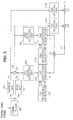
- the apparatus for separating luminance and chrominance signals according to the present invention uses a filtering means as shown in FIG.3 in place of a conventional band pass filter 50.
- the filtering means comprises:
- S1 shows the frequency characteristic of a chrominance signal, which has passed through the narrow band pass filter 60, with a narrow frequency band of 3.58 ⁇ 0.5MHz.
- S2 shows the frequency characteristic of a chrominance signal, which has passed through the wide band pass filter 70, with a wide frequency band of 3.58 ⁇ 1.5MHz.
- S3 shows the frequency characteristic of a transition chrominance signal which is a difference component between the signals S1 and S2 and shows the degree of color change.
- C shows the characteristic of a finally separated chrominance signal.
- FIG.5 is a block diagram detailedly showing the first and second level detecting units 80 and 90 in FIG.3.
- each level detecting unit comprises an absolute value detector, a delaying unit, and a maximum value detector.
- a chrominance signal primarily separated in the comb-filter 40 is input to the narrow band pass filter 60 and the wide band pass filter 70.
- the comb-filtered chrominance signal is varied from a signal Q to a signal I according to the color change, as shown in FIG.1, and also includes a luminance signal Y that is not completely separated during comb-filtering.
- the narrow band pass filter 60 and the wide band pass filter 70 which have frequency bands of 3.58 ⁇ 0.5 MHz and 3.58 ⁇ 1.5MHz, respectively, output the signal S1 of a narrow frequency band and the signal S2 of a wide frequency band, respectively.
- the two signals S1 and S2 are supplied respectively to a first subtracter 31 to output a transition chrominance signal S3 which is a difference component between the two signals S1 and S2.
- the chrominance signal S2 outputted from the wide band pass filter 70 is input to a first absolute value detector 81, in which the chrominance signal S2 is converted to an absolute value.
- the chrominance signal output of an absolute value supplied from the first absolute value detector 81 is directly input to a first maximum value detector 83, and concurrently is delayed by 90 degrees via a third delaying unit 82 and is then supplied to the first maximum value detector 83.
- the first maximum value detector 83 detects the maximum value between the inputted two signals, thereby detecting an amplitude of a chrominance signal.
- the first coefficient generator 100 receives the maximum value corresponding to the detected amplitude of the chrominance signal, and compares it with the predetermined reference values generated from the first reference generator 120, thereby generating an n-bit coefficient.
- the transition chrominance signal S3 passes through a second absolute value detector 91, a fourth delaying unit 92, and a second maximum value detector 93, like the chrominance signal S2, so a degree of color change is detected.
- the second coefficient generator 110 receives the maximum value of the detected degree of color change supplied from the second maximum value detector 93, and compares it with the predetermined reference values generated from the second reference generator 130, thereby generating an n-bit coefficient.
- the n-bit coefficients respectively generated in the first and second coefficient generators 100 and 110 are multiplied in a first multiplier 32, so that a 2n-bit final coefficient is obtained.
- the transition chrominance signal S3 is input to the first delaying unit 140 connected in parallel with the second level detecting unit 90.
- the first delaying unit 140 delays the inputted transition chrominance signal S3 for a predetermined time, and then supplies it to the second multiplier 33, thereby matching the final coefficient received at the other input terminal of the second multiplier 33 with the delayed transition chrominance signal in the second multiplier 33.
- the delayed transition chrominance signal is multiplied by the 2n-bit final coefficient in the second multiplier 33, a transition chrominance signal whose amplitude is determined according to the amplitude of the chrominance signal and a degree of color change is obtained.
- the chrominance signal S1 output from the narrow band pass filter is input to the second delaying unit 150 connected in parallel with the first subtracter 31.
- the second delaying unit 150 delays the inputted chrominance signal S1 for a predetermined interval and transmits the delayed chrominance signal to an adder 34, thereby matching the output signal of the second multiplier 33 received at the other input terminal of the adder 34 with the delayed chrominance signal in the adder 34.
- the chrominance signal having a frequency characteristic such as "C" of FIG.4 is obtained (where, the frequency characteristic shown in this drawing shows when the final coefficient is about 0.5).
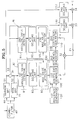
- each of the coefficients generated from the first and second coefficient generators 100 and 110 is of 2 bits, and a combinational logic circuit 170 and a multiplexer 180 are provided in place of the first and second multipliers 32 and 33, simplifying control of the outputted transition chrominance signal.
- a first coefficient generator 100 receives the maximum value corresponding to an amplitude of a chrominance signal outputted from the first level detecting unit 80, and compares the amplitude of the chrominance signal with three reference values generated in the first reference generator 120, thereby generating a 2-bit coefficient as the result.
- the second coefficient generator 110 generates a coefficient corresponding to the degree of the color change, thereby generating a 2-bit coefficient.
- the combinational logic circuit 170 receives the coefficients respectively generated in the first and second coefficient generators 100 and 110 and then supplies a 2-bit selection signal and an enable signal to the multiplexer 180.
- transition chrominance signal S3 output from the first subtracter 31 is input to the fifth delaying unit 160, where the amplitude of the signal S3 is modified into three-quarters, a half, a quarter times, respectively, which are output with the original signal through four output terminals of the fifth delaying unit 160, respectively.
- the multiplexer 180 receives two control signals outputted from the combinational logic circuit 170 and four transition chrominance signals outputted from the fifth delaying unit 160, respectively, and selects one of the four transition chrominance signals having different amplitudes by the two control signals.
- the enable signal is received at the enable terminal of the multiplexer 180 from the combinational logic circuit 170 and the 2-bit selection signal outputted from the combinational logic circuit 170 is input to the selection terminal of the multiplexer 180, one of the inputted transition chrominance signals whose amplitudes have been converted into a quarter, a half, three quarters, and one times is selected, according to the data value of the selection signal having one of the following binary values 00, 01, 10 and 11.
- the following table 1 shows the results when one of the four color transition signals is selected according to the two control signal generated by the first and second coefficients.
- Karnaugh maps are made with respect to the first and second 2-bit coefficients, which are input signals, and an enable signal and a 2-bit selection signal, which are output signals, so that the combinational logic circuit 170 is accomplished by a plurality of AND and OR gates. Since the transition chrominance signal selected in this manner and transmitted from the multiplexer 180 to the adder 34 is added to the output signal S1 of the narrow band pass filter 60 passed through the second delaying unit 150, in the adder 34, as referenced in FIG.5, the finally separated chrominance signal C is obtained. Accordingly, the finally separated chrominance signal C is input to the subtracter 30 as described in FIG.2 and then is subtracted from the composite video signal delayed for a predetermined interval, so that the separated luminance signal Y can be detected.
- an apparatus for separating luminance and chrominance signals and the method thereof is provided with a filtering means and the method thereof for separating a chrominance signal by changing the bandwidth according to an amplitude of a chrominance signal and a degree of color change, instead of a conventional band pass filter having a fixed frequency band, thereby preventing a cross color phenomenon and a dot crawl phenomenon so as to provide a further improved picture.
Landscapes
- Engineering & Computer Science (AREA)
- Multimedia (AREA)
- Signal Processing (AREA)
- Processing Of Color Television Signals (AREA)
Claims (9)
- Vorrichtung zur Trennung des Luminanzsignals und des Chrominanzsignals, die umfaßt:eine analog/digital Umsetzungseinrichtung (10) zum Umsetzen eines analogen zusammengesetzten Videosignal-Eingangs in einen digitalen zusammengesetzten Videosignal-Ausgang;eine Verzögerungseinrichtung (20) zum Verzögern des digitalen zusammengesetzten Videosignals um ein vorbestimmtes Intervall;einen Kammfilter (40), der mit der Verzögerungseinrichtung (20) parallel geschaltet ist, zum Kamm-Filtern des digitalen zusammengesetzten Videosignals;eine Bandpaßfilter-Einrichtung (50) zum Empfangen des eine Luminanzkomponente enthaltenden, Kamm-gefilterten Chrominanzsignals vom Kammfilter (40), und zum Filtern des Kamm-gefilterten Chrominanzsignals durch Ändern seiner Frequenz-Bandbreite gemäß einer Amplitude eines Chrominanzsignals und einem Grad an Farbänderung, um ein schließlich getrenntes Chrominanzsignal auszugeben; undeine Subtraktionseinrichtung (30) zum Subtrahieren des schließlich getrennten Chrominanzsignals von dem verzögerten digitalen zusammengesetzten Videosignal, das von der Verzögerungseinrichtung (20) zugeführt wird, um ein schließlich getrenntes Luminanzsignal auszugeben,dadurch gekennzeichnet, daß
die Bandpaßfilter-Einrichtung umfaßt:einen Schmalbandfilter (60) zum Filtern des vom Kammfilter ausgegebenen Kamm-gefilterten Signals in ein schmales Frequenzband;einen Breitbandfilter (70), der parallel zu dem Schmalbandfilter (60) mit einem Ausgang des Kammfilters (40) verbunden ist, zum Filtern des Kamm-gefilterten Signals in ein breites Frequenzband;eine erste Pegel-Detektionseinrichtung (80) zum Empfangen eines Ausgangssignals des Breitbandfilters (70) und zum Detektieren einer Amplitude eines Chrominanzsignals;einen Subtrahierer (31) zum Subtrahieren des Ausgangs des Schmalbandfilters (60) vom Ausgang des Breitbandfilters (70), um ein Übergangs-Chrominanzsignal auszugeben;eine zweite Pegel-Detektionseinrichtung (90) zum Emfangen des Übergangs-Chrominanzsignals, das eine Differenz zwischen jeweiligen von dem Breitbandfilter (70) und dem Schmalbandfilter (60) ausgegebenen Signalen darstellt, und zum Detektieren eines Grades an Farbänderung;eine erste Koeffizienten-Erzeugungseinrichtung (100) zum Erzeugen eines Koeffizienten aus der von der ersten Pegel-Detektionseinrichtung (80) ausgegebenen Amplitude eines Chrominanzsignals;eine zweite Koeffizienten-Erzeugungseinrichtung (110) zum Erzeugen eines Koeffizienten entsprechend dem von der zweiten Pegel-Detektionseinrichtung (90) ausgegebenen Grad an Farbänderung;eine erste Verzögerungseinrichtung (140), die mit der zweiten Pegel-Detektionseinrichtung (90) parallel geschaltet ist, zum Verzögern des Übergangs-Chrominanzsignals (S3) um ein vorbestimmtes Intervall;eine zweite Verzögerungseinrichtung (150) zum Verzögern eines vom Schmalbandfilter (60) ausgegebenen Signals (S1) um ein vorbestimmtes Intervall;eine Einrichtung zum Multiplizieren (33) eines Koeffizienten, der durch Multiplizieren (32) von jeweils von der ersten Koeffizienten-Erzeugungseinrichtung und von der zweiten Koeffizienten-Erzeugungseinrichtung ausgegebenen Koeffizienten erhalten wird, mit einem von der ersten Verzögerungseinrichtung (140) ausgegebenen Signal, und zum Addieren (34) eines aus dem Multiplikationsprodukt erhaltenen Signals und eines von der zweiten Verzögerungseinrichtung (150) ausgegebenen Signals, so daß ein schließlich getrenntes Chrominanzsignal (C) ausgegeben wird. - Vorrichtung zur Trennung des Luminanzsignals und des Chrominanzsignals wie in Anspruch 1 beansprucht, in der die erste Pegel-Detektionseinrichtung (80) umfaßt:eine erste Absolutwert-Detektionseinrichtung (81) zum Umsetzen eines vom Breitbandfilter (70) ausgegebenen Signals in einen Absolutwert, der dann ausgegeben wird;eine dritte Verzögerungseinrichtung (82) zum Verzögern eines von der ersten Absolutwert-Detektionseinrichtung (81) ausgegebenen Signals um ein vorbestimmtes Intervall; undeine erste Maximalwert-Detektionseinrichtung (83) zum Empfangen von Ausgangssignalen der ersten Absolutwert-Detektionseinrichtung (81) und der dritten Verzögerungseinrichtung (82), und zum Zuführen eines Maximalwertes entsprechend der Amplitude eines Chrominanzsignals zu der ersten Koeffizienten-Erzeugungseinrichtung (100).
- Vorrichtung zur Trennung des Luminanzsignals und des Chrominanzsignals wie in Anspruch 1 beansprucht, in der die zweite Pegel-Detektionseinrichtung (90) umfaßt:eine zweite Absolutwert-Detektionseinrichtung (91) zum Umsetzen des eingegebenen Übergangs-Chrominanzsignals in einen Absolutwert, der dann ausgegeben wird;eine vierte Verzögerungseinrichtung (92) zum Verzögern eines von der zweiten Absolutwert-Detektionseinrichtung (91) ausgegebenen Signals um ein vorbestimmtes Intervall; undeine zweite Maximalwert-Detektionseinrichtung (93) zum Empfangen von Ausgangssignalen der zweiten Absolutwert-Detektionseinrichtung (91) und der vierten Verzögerungseinrichtung (92), und zum Zuführen eines Maximalwertes entsprechend dem Grad einer Farbänderung zu der zweiten Koeffizienten-Erzeugungseinrichtung (110).
- Vorrichtung zur Trennung des Luminanzsignals und des Chrominanzsignals, die umfaßt:eine analog/digital Umsetzungseinrichtung (10) zum Umsetzen eines analogen zusammengesetzten Videosignal-Eingangs in einen digitalen zusammengesetzten Videosignal-Ausgang;eine Verzögerungseinrichtung (20) zum Verzögern des digitalen zusammengesetzten Videosignals um ein vorbestimmtes Intervall;einen Kammfilter (40), der mit der Verzögerungseinrichtung (20) parallel geschaltet ist, zum Kamm-Filtern des digitalen zusammengesetzten Videosignals;eine Bandpaßfilter-Einrichtung (50) zum Empfangen des eine Luminanzkomponente enthaltenden, Kamm-gefilterten Chrominanzsignals vom Kammfilter (40), und zum Filtern des Kamm-gefilterten Chrominanzsignals durch Ändern seiner Frequenz-Bandbreite gemäß einer Amplitude eines Chrominanzsignals und einem Grad an Farbänderung, um ein schließlich getrenntes Chrominanzsignal auszugeben; undeine Subtraktionseinrichtung (30) zum Subtrahieren des schließlich getrennten Chrominanzsignals von dem verzögerten digitalen zusammengesetzten Videosignal, das von der Verzögerungseinrichtung (20) zugeführt wird, um ein schließlich getrenntes Luminanzsignal auszugeben,dadurch gekennzeichnet, daß
die Bandpaßfilter-Einrichtung umfaßt:einen Schmalbandfilter (60) zum Filtern eines vom Kammfilter ausgegebenen Signals in ein schmales Frequenzband;einen Breitbandfilter (70), der parallel zu dem Schmalbandfilter (60) mit dem Kammfilter (40) verbunden ist, zum Filtern des Kamm-gefilterten Signals in ein breites Frequenzband;eine erste Pegel-Detektionseinrichtung (80) zum Empfangen eines Ausgangssignals des Breitbandfilters (70) und zum Detektieren einer Amplitude eines Chrominanzsignals;einen Subtrahierer (31) zum Subtrahieren des Ausgangs des Schmalbandfilters (60) vom Ausgang des Breitbandfilters (70), um ein Übergangs-Chrominanzsignal auszugeben;eine zweite Pegel-Detektionseinrichtung (90) zum Emfangen des Übergangs-Chrominanzsignals, das eine Differenz zwischen von dem Breitbandfilter (70) und dem Schmalbandfilter (60) jeweils ausgegebenen Signalen darstellt, und zum Detektieren eines Grades an Farbänderung;eine erste Koeffizienten-Erzeugungseinrichtung (100) zum Erzeugen eines Koeffizienten entsprechend der von der ersten Pegel-Detektionseinrichtung (80) ausgegebenen Amplitude eines Chrominanzsignals;eine zweite Koeffizienten-Erzeugungseinrichtung (110) zum Erzeugen eines Koeffizienten entsprechend dem von der zweiten Pegel-Detektionseinrichtung (90) ausgegebenen Grad einer Farbänderung;eine zweite Verzögerungseinrichtung (150) zum Verzögern eines vom Schmalbandfilter (60) ausgegebenen Signals um ein vorbestimmtes Intervall;eine fünfte Verzögerungseinrichtung (160), die mit der zweiten Pegel-Detektionseinrichtung (90) parallel geschaltet ist, zum Verzögern des Übergangs-Chrominanzsignals um ein vorbestimmtes Intervall und auch zum Multiplizieren der Amplitude des Übergangs-Chrominanzsignals mit vorbestimmten Vergrößerungen, und zum nachfolgenden Ausgeben der Signale entsprechend den vergrößerten Amplituden des Übergangs-Chrominanzsignals jeweils durch eine Mehrzahl von Ausgangsanschlüssen;eine Kombinations-Logikeinrichtung (170) zum Empfangen von Koeffizienten, die jeweils von der ersten Koeffizienten-Erzeugungseinrichtung (100) und der zweiten Koeffizienten-Erzeugungseinrichtung (110) ausgegeben werden, und zum nachfolgenden Ausgeben von Steuersignalen;einen Multiplexer (180) zum Auswählen eines Signals aus einer Mehrzahl von Signalen, die von der fünften Verzögerungseinrichtung (160) durch eine Mehrzahl von Eingangsanschlüssen empfangen werden, durch die Steuersignale, und nachfolgendes Ausgeben des ausgewählten Signals; undeine Addiereinrichtung (34) zum Addieren von Ausgangssignalen der zweiten Verzögerungseinrichtung (150) und des Multiplexers (180), und nachfolgendes Ausgeben eines schließlich getrennten Chrominanzsignals (C). - Vorrichtung zur Trennung des Luminanzsignals und des Chrominanzsignals wie in Anspruch 4 beansprucht, in der die erste Pegel-Detektionseinrichtung (80) umfaßt:eine erste Absolutwert-Detektionseinrichtung (81) zum Umsetzen eines vom Breitbandfilter (70) ausgegebenen Signals (S2) in einen Absolutwert;eine dritte Verzögerungseinrichtung (82) zum Verzögern eines von der ersten Absolutwert-Detektionseinrichtung (81) ausgegebenen Signals um ein vorbestimmtes Intervall; undeine erste Maximalwert-Detektionseinrichtung (83) zum Empfangen von Ausgangssignalen der ersten Absolutwert-Detektionseinrichtung und der dritten Verzögerungseinrichtung, und zum nachfolgenden Zuführen eines Maximalwertes entsprechend der Amplitude eines Chrominanzsignals zu der ersten Koeffizienten-Erzeugungseinrichtung (100).
- Vorrichtung zur Trennung des Luminanzsignals und des Chrominanzsignals wie in Anspruch 4 beansprucht, in der die zweite Pegel-Detektionseinrichtung (90) umfaßt:eine zweite Absolutwert-Detektionseinrichtung (91) zum Umsetzen des eingegebenen Übergangs-Chrominanzsignals in einen Absolutwert;eine vierte Verzögerungseinrichtung (92) zum Verzögern eines von der zweiten Absolutwert-Detektionseinrichtung (91) ausgegebenen Signals um ein vorbestimmtes Intervall; undeine zweite Maximalwert-Detektionseinrichtung (93) zum Empfangen von Ausgangssignalen der zweiten Absolutwert-Detektionseinrichtung (91) und der vierten Verzögerungseinrichtung (92), und zum Zuführen eines Maximalwertes entsprechend dem Grad einer Farbänderung zu der zweiten Koeffizienten-Erzeugungseinrichtung (110).
- Verfahren zur Trennung des Luminanzsignals und des Chrominanzsignals, das die Schritte umfaßt:Umsetzen eines eingegebenen analogen zusammengesetzten Videosignals in ein digitales zusammengesetztes Videosignal;Verzögern des digitalen zusammengesetzten Videosignals um ein vorbestimmtes Intervall;Kamm-Filtern des digitalen zusammengesetzten Videosignals;Filtern des Kamm-gefilterten Signals in ein variables Band durch Ändern der Frequenz-Bandbreite gemäß einer Amplitude eines Chrominanzsignals und einem Grad an Farbänderung, enthalten im Kamm-gefilterten Signal, um ein gewünschtes Chrominanzsignal auszugeben; undExtrahieren eines gewünschten Luminanzsignals durch Subtrahieren des in das variable Band gefilterten Chrominanzsignals von dem verzögerten zusammengesetzten Videosignal,dadurch gekennzeichnet, daß
der Filter-Schritt in ein variables Band die Schritte umfaßt:Filtern des Kamm-gefilterten Signals in ein schmales Band und ein breites Band;Detektieren einer Amplitude des Breitband-gefilterten Chrominanzsignals;Subtrahieren des Schmalband-gefilterten Chrominanzsignals vom Breitband-gefilterten Chrominanzsignal um ein Übergangs-Chrominanzsignal zu erhalten, das eine Differenz zwischen dem Schmalband-gefilterten Signal und dem Breitband-gefilterten Signal ist, und Detektieren eines Grades an Farbänderung;Erzeugen eines Koeffizienten entsprechend der detektierten Amplitude des Chrominanzsignals;Erzeugen eines Koeffizienten entsprechend dem detektierten Grad der Farbänderung;Extrahieren eines schließlich getrennten Chrominanzsignals durch Multiplizieren eines Koeffizienten, der durch Multiplizieren zweier jeweils aus der Amplitude des Chrominanzsignals und dem Grad der Farbänderung erhaltenen Koeffizienten erhalten wird, mit einem Signal, das ein um ein vorbestimmtes Intervall verzögertes Übergangs-Chrominanzsignal ist, und Addieren des aus dem Multiplikationsprodukt erhaltenen Signals und des Signals, das ein um ein vorbestimmtes Intervall verzögertes Schmalband-gefiltertes Signal ist. - Verfahren zur Trennung des Luminanzsignals und des Chrominanzsignals gemäß Anspruch 7,
dadurch gekennzeichnet, daß
der Chrominanzsignalamplituden-Detektionsschritt die Schritte umfaßt:Umsetzen des Breitband-gefilterten Signals in einen Absolutwert;Verzögern des in einen Absolutwert umgesetzten Signals um ein vorbestimmtes Intervall; undDetektieren des Maximalwertes aus dem in einen Absolutwert umgesetzten Signal und dem um ein vorbestimmtes Intervall verzögerten Signal. - Verfahren zur Trennung des Luminanzsignals und des Chrominanzsignals gemäß Anspruch 7,
dadurch gekennzeichnet, daß
der Farbänderungsgrad-Detektionsschritt die Schritte umfaßt:Umsetzen des Übergangs-Chrominanzsignals in einen Absolutwert;Verzögern des in einen Absolutwert umgesetzten Signals um ein vorbestimmtes Intervall; undDetektieren des Maximalwertes aus dem in einen Absolutwert umgesetzten Signal und dem um ein vorbestimmtes Intervall verzögerten Signal.
Applications Claiming Priority (2)
| Application Number | Priority Date | Filing Date | Title |
|---|---|---|---|
| KR987490 | 1990-06-30 | ||
| KR1019900009874A KR930008184B1 (ko) | 1990-06-30 | 1990-06-30 | 휘도/색신호 분리 회로 |
Publications (3)
| Publication Number | Publication Date |
|---|---|
| EP0464879A2 EP0464879A2 (de) | 1992-01-08 |
| EP0464879A3 EP0464879A3 (en) | 1993-06-09 |
| EP0464879B1 true EP0464879B1 (de) | 1997-11-26 |
Family
ID=19300733
Family Applications (1)
| Application Number | Title | Priority Date | Filing Date |
|---|---|---|---|
| EP91201213A Expired - Lifetime EP0464879B1 (de) | 1990-06-30 | 1991-05-22 | Vorrichtung zur Trennung des Luminanzsignals und des Chrominanzsignals und Verfahren |
Country Status (5)
| Country | Link |
|---|---|
| US (1) | US5194942A (de) |
| EP (1) | EP0464879B1 (de) |
| JP (1) | JP3021087B2 (de) |
| KR (1) | KR930008184B1 (de) |
| DE (1) | DE69128259T2 (de) |
Families Citing this family (8)
| Publication number | Priority date | Publication date | Assignee | Title |
|---|---|---|---|---|
| KR950012838B1 (ko) * | 1992-07-31 | 1995-10-21 | 엘지전자주식회사 | 직교변조형 칼라 텔레비젼 수상기의 휘도/칼라신호 분리장치 |
| JP3263791B2 (ja) * | 1992-09-30 | 2002-03-11 | ソニー株式会社 | Yc分離回路 |
| US5345407A (en) * | 1993-08-23 | 1994-09-06 | Motorola, Inc. | Digital multiband filter and method thereof |
| JP3216365B2 (ja) * | 1993-10-21 | 2001-10-09 | 松下電器産業株式会社 | Y/c分離装置 |
| US7138886B2 (en) * | 2002-05-02 | 2006-11-21 | Xtend Networks Ltd. | Wideband CATV signal splitter device |
| US20070063790A1 (en) * | 2005-05-19 | 2007-03-22 | Yeshayahu Strull | Wideband CATV signal splitter device |
| CN102123289B (zh) * | 2010-12-28 | 2013-12-25 | 华亚微电子(上海)有限公司 | 一种三维梳状滤波中估计图像运动方法及装置 |
| KR20160109069A (ko) | 2015-03-09 | 2016-09-21 | 김인균 | 공기 가압식 이송장치 |
Family Cites Families (9)
| Publication number | Priority date | Publication date | Assignee | Title |
|---|---|---|---|---|
| JPS5760791A (en) * | 1980-09-30 | 1982-04-12 | Toshiba Corp | Demodulating circuit for wide-band receiving chrominance |
| US4626894A (en) * | 1984-10-04 | 1986-12-02 | Rca Corporation | Signal filtering system having adaptively cascaded filter stages for developing a variable bandwidth frequency characteristic |
| JPS61113486U (de) * | 1984-12-27 | 1986-07-17 | ||
| JPS62125792A (ja) * | 1985-11-26 | 1987-06-08 | Nec Home Electronics Ltd | Y/c分離用くし型フイルタ− |
| US4916526A (en) * | 1986-01-31 | 1990-04-10 | Yves C. Faroudja | Bandwidth control for chrominance and luminance paths in quadrature modulated color television system |
| JPS6330085A (ja) * | 1986-07-23 | 1988-02-08 | Hitachi Ltd | 輝度信号・色信号分離回路 |
| JPH01136492A (ja) * | 1987-11-24 | 1989-05-29 | Victor Co Of Japan Ltd | 映像信号処理装置 |
| US5097321A (en) * | 1989-04-28 | 1992-03-17 | Accom | Three dimensional adaptive decoding system and method |
| JPH03243088A (ja) * | 1990-02-21 | 1991-10-30 | Sanyo Electric Co Ltd | Y/c分離回路 |
-
1990
- 1990-06-30 KR KR1019900009874A patent/KR930008184B1/ko not_active Expired - Fee Related
-
1991
- 1991-05-22 EP EP91201213A patent/EP0464879B1/de not_active Expired - Lifetime
- 1991-05-22 DE DE69128259T patent/DE69128259T2/de not_active Expired - Fee Related
- 1991-05-22 US US07/704,377 patent/US5194942A/en not_active Expired - Lifetime
- 1991-05-30 JP JP3127119A patent/JP3021087B2/ja not_active Expired - Fee Related
Also Published As
| Publication number | Publication date |
|---|---|
| EP0464879A3 (en) | 1993-06-09 |
| EP0464879A2 (de) | 1992-01-08 |
| US5194942A (en) | 1993-03-16 |
| JPH04233888A (ja) | 1992-08-21 |
| DE69128259D1 (de) | 1998-01-08 |
| KR930008184B1 (ko) | 1993-08-26 |
| DE69128259T2 (de) | 1998-05-28 |
| JP3021087B2 (ja) | 2000-03-15 |
| KR920001976A (ko) | 1992-01-30 |
Similar Documents
| Publication | Publication Date | Title |
|---|---|---|
| US5333054A (en) | Apparatus for reducing noise in a video signal by processing a luminance and chrominance component | |
| KR19990007950A (ko) | 공통 지연 소자를 갖는 휘도/색차 분리필터 | |
| US4644389A (en) | Digital television signal processing circuit | |
| US6614489B1 (en) | Method of processing signals and apparatus for signal processing | |
| US5225899A (en) | Correlation adaptive luminance and chrominance signal separating circuit | |
| US5583579A (en) | Two-dimensional adaptation type luminance/chrominance signal separation apparatatus | |
| US5194942A (en) | Variable bandwidth control apparatus for separating luminance and chrominance signals and the method thereof | |
| US4819062A (en) | Adaptive-type luminance/color signal separation circuit using the horizontal and vertical correlation in television receiver | |
| US4333104A (en) | Color demodulating apparatus with cross-color cancellation | |
| US5140410A (en) | Chrominance signal mixing circuit in a motion adaptive type signal separator | |
| US5087967A (en) | Color image pickup device having a level correcting circuit for correcting level variations in color image signals | |
| KR920002274B1 (ko) | 운동 보상회로 | |
| US6798902B1 (en) | Method of processing signals and apparatus for signal processing | |
| EP1073283A2 (de) | Verfahren und Vorrichtung zur Signalverarbeitung | |
| US5929938A (en) | Motion adaptive luminance and chrominance signal separating circuit | |
| US4953009A (en) | Signal separator having function of subsampling digital composite video signal | |
| JP3330146B2 (ja) | テレビジョン信号符号化方法及び復号化装置 | |
| EP1073281A2 (de) | Verfahren und Vorrichtung zur Signalverarbeitung | |
| EP0161923A2 (de) | Trennungsfilter von Leuchtdichte- und Farbensignalen eines PAL-Systems | |
| US6704443B1 (en) | Method of processing signals and apparatus for signal processing | |
| JPH0225599B2 (de) | ||
| US6798462B1 (en) | Method of processing signals and apparatus for signal processing | |
| JP3257804B2 (ja) | A/d変換用回路配置 | |
| JP2557511B2 (ja) | テレビジョン表示画面の動き検出回路 | |
| KR920010039B1 (ko) | 칼라신호 복조회로 |
Legal Events
| Date | Code | Title | Description |
|---|---|---|---|
| PUAI | Public reference made under article 153(3) epc to a published international application that has entered the european phase |
Free format text: ORIGINAL CODE: 0009012 |
|
| AK | Designated contracting states |
Kind code of ref document: A2 Designated state(s): DE FR GB NL SE |
|
| 17P | Request for examination filed |
Effective date: 19920605 |
|
| PUAL | Search report despatched |
Free format text: ORIGINAL CODE: 0009013 |
|
| AK | Designated contracting states |
Kind code of ref document: A3 Designated state(s): DE FR GB NL SE |
|
| 17Q | First examination report despatched |
Effective date: 19950630 |
|
| GRAG | Despatch of communication of intention to grant |
Free format text: ORIGINAL CODE: EPIDOS AGRA |
|
| GRAH | Despatch of communication of intention to grant a patent |
Free format text: ORIGINAL CODE: EPIDOS IGRA |
|
| GRAH | Despatch of communication of intention to grant a patent |
Free format text: ORIGINAL CODE: EPIDOS IGRA |
|
| GRAA | (expected) grant |
Free format text: ORIGINAL CODE: 0009210 |
|
| AK | Designated contracting states |
Kind code of ref document: B1 Designated state(s): DE FR GB NL SE |
|
| REF | Corresponds to: |
Ref document number: 69128259 Country of ref document: DE Date of ref document: 19980108 |
|
| ET | Fr: translation filed | ||
| PLBE | No opposition filed within time limit |
Free format text: ORIGINAL CODE: 0009261 |
|
| STAA | Information on the status of an ep patent application or granted ep patent |
Free format text: STATUS: NO OPPOSITION FILED WITHIN TIME LIMIT |
|
| 26N | No opposition filed | ||
| REG | Reference to a national code |
Ref country code: GB Ref legal event code: IF02 |
|
| PGFP | Annual fee paid to national office [announced via postgrant information from national office to epo] |
Ref country code: NL Payment date: 20090504 Year of fee payment: 19 |
|
| PGFP | Annual fee paid to national office [announced via postgrant information from national office to epo] |
Ref country code: DE Payment date: 20090514 Year of fee payment: 19 Ref country code: SE Payment date: 20090512 Year of fee payment: 19 Ref country code: FR Payment date: 20090515 Year of fee payment: 19 |
|
| PGFP | Annual fee paid to national office [announced via postgrant information from national office to epo] |
Ref country code: GB Payment date: 20090520 Year of fee payment: 19 |
|
| REG | Reference to a national code |
Ref country code: NL Ref legal event code: V1 Effective date: 20101201 |
|
| GBPC | Gb: european patent ceased through non-payment of renewal fee |
Effective date: 20100522 |
|
| EUG | Se: european patent has lapsed | ||
| REG | Reference to a national code |
Ref country code: FR Ref legal event code: ST Effective date: 20110131 |
|
| PG25 | Lapsed in a contracting state [announced via postgrant information from national office to epo] |
Ref country code: SE Free format text: LAPSE BECAUSE OF NON-PAYMENT OF DUE FEES Effective date: 20100523 Ref country code: NL Free format text: LAPSE BECAUSE OF NON-PAYMENT OF DUE FEES Effective date: 20101201 |
|
| PG25 | Lapsed in a contracting state [announced via postgrant information from national office to epo] |
Ref country code: DE Free format text: LAPSE BECAUSE OF NON-PAYMENT OF DUE FEES Effective date: 20101201 |
|
| PG25 | Lapsed in a contracting state [announced via postgrant information from national office to epo] |
Ref country code: FR Free format text: LAPSE BECAUSE OF NON-PAYMENT OF DUE FEES Effective date: 20100531 |
|
| PG25 | Lapsed in a contracting state [announced via postgrant information from national office to epo] |
Ref country code: GB Free format text: LAPSE BECAUSE OF NON-PAYMENT OF DUE FEES Effective date: 20100522 |