EP0464933A2 - Dispositif et procédé pour la fabrication de récipients en matière plastique, tels que bouteilles, avec parois multi-couches - Google Patents
Dispositif et procédé pour la fabrication de récipients en matière plastique, tels que bouteilles, avec parois multi-couches Download PDFInfo
- Publication number
- EP0464933A2 EP0464933A2 EP91201660A EP91201660A EP0464933A2 EP 0464933 A2 EP0464933 A2 EP 0464933A2 EP 91201660 A EP91201660 A EP 91201660A EP 91201660 A EP91201660 A EP 91201660A EP 0464933 A2 EP0464933 A2 EP 0464933A2
- Authority
- EP
- European Patent Office
- Prior art keywords
- mould
- parison
- turntable
- moulding
- container
- Prior art date
- Legal status (The legal status is an assumption and is not a legal conclusion. Google has not performed a legal analysis and makes no representation as to the accuracy of the status listed.)
- Withdrawn
Links
Images


Classifications
-
- B—PERFORMING OPERATIONS; TRANSPORTING
- B29—WORKING OF PLASTICS; WORKING OF SUBSTANCES IN A PLASTIC STATE IN GENERAL
- B29C—SHAPING OR JOINING OF PLASTICS; SHAPING OF MATERIAL IN A PLASTIC STATE, NOT OTHERWISE PROVIDED FOR; AFTER-TREATMENT OF THE SHAPED PRODUCTS, e.g. REPAIRING
- B29C49/00—Blow-moulding, i.e. blowing a preform or parison to a desired shape within a mould; Apparatus therefor
- B29C49/28—Blow-moulding apparatus
- B29C49/30—Blow-moulding apparatus having movable moulds or mould parts
- B29C49/36—Blow-moulding apparatus having movable moulds or mould parts rotatable about one axis
-
- B—PERFORMING OPERATIONS; TRANSPORTING
- B29—WORKING OF PLASTICS; WORKING OF SUBSTANCES IN A PLASTIC STATE IN GENERAL
- B29C—SHAPING OR JOINING OF PLASTICS; SHAPING OF MATERIAL IN A PLASTIC STATE, NOT OTHERWISE PROVIDED FOR; AFTER-TREATMENT OF THE SHAPED PRODUCTS, e.g. REPAIRING
- B29C49/00—Blow-moulding, i.e. blowing a preform or parison to a desired shape within a mould; Apparatus therefor
- B29C49/02—Combined blow-moulding and manufacture of the preform or the parison
- B29C49/04—Extrusion blow-moulding
- B29C49/0412—Means for cutting the extruded preform
-
- B—PERFORMING OPERATIONS; TRANSPORTING
- B29—WORKING OF PLASTICS; WORKING OF SUBSTANCES IN A PLASTIC STATE IN GENERAL
- B29C—SHAPING OR JOINING OF PLASTICS; SHAPING OF MATERIAL IN A PLASTIC STATE, NOT OTHERWISE PROVIDED FOR; AFTER-TREATMENT OF THE SHAPED PRODUCTS, e.g. REPAIRING
- B29C49/00—Blow-moulding, i.e. blowing a preform or parison to a desired shape within a mould; Apparatus therefor
- B29C49/22—Blow-moulding, i.e. blowing a preform or parison to a desired shape within a mould; Apparatus therefor using multilayered preforms or parisons
-
- B—PERFORMING OPERATIONS; TRANSPORTING
- B29—WORKING OF PLASTICS; WORKING OF SUBSTANCES IN A PLASTIC STATE IN GENERAL
- B29C—SHAPING OR JOINING OF PLASTICS; SHAPING OF MATERIAL IN A PLASTIC STATE, NOT OTHERWISE PROVIDED FOR; AFTER-TREATMENT OF THE SHAPED PRODUCTS, e.g. REPAIRING
- B29C49/00—Blow-moulding, i.e. blowing a preform or parison to a desired shape within a mould; Apparatus therefor
- B29C49/42—Component parts, details or accessories; Auxiliary operations
- B29C49/46—Component parts, details or accessories; Auxiliary operations characterised by using particular environment or blow fluids other than air
-
- B—PERFORMING OPERATIONS; TRANSPORTING
- B29—WORKING OF PLASTICS; WORKING OF SUBSTANCES IN A PLASTIC STATE IN GENERAL
- B29C—SHAPING OR JOINING OF PLASTICS; SHAPING OF MATERIAL IN A PLASTIC STATE, NOT OTHERWISE PROVIDED FOR; AFTER-TREATMENT OF THE SHAPED PRODUCTS, e.g. REPAIRING
- B29C49/00—Blow-moulding, i.e. blowing a preform or parison to a desired shape within a mould; Apparatus therefor
- B29C49/42—Component parts, details or accessories; Auxiliary operations
- B29C49/46—Component parts, details or accessories; Auxiliary operations characterised by using particular environment or blow fluids other than air
- B29C2049/4602—Blowing fluids
- B29C2049/4635—Blowing fluids being sterile
-
- B—PERFORMING OPERATIONS; TRANSPORTING
- B29—WORKING OF PLASTICS; WORKING OF SUBSTANCES IN A PLASTIC STATE IN GENERAL
- B29C—SHAPING OR JOINING OF PLASTICS; SHAPING OF MATERIAL IN A PLASTIC STATE, NOT OTHERWISE PROVIDED FOR; AFTER-TREATMENT OF THE SHAPED PRODUCTS, e.g. REPAIRING
- B29C49/00—Blow-moulding, i.e. blowing a preform or parison to a desired shape within a mould; Apparatus therefor
- B29C49/42—Component parts, details or accessories; Auxiliary operations
- B29C49/46—Component parts, details or accessories; Auxiliary operations characterised by using particular environment or blow fluids other than air
- B29C2049/4673—Environments
- B29C2049/4697—Clean room
-
- B—PERFORMING OPERATIONS; TRANSPORTING
- B29—WORKING OF PLASTICS; WORKING OF SUBSTANCES IN A PLASTIC STATE IN GENERAL
- B29L—INDEXING SCHEME ASSOCIATED WITH SUBCLASS B29C, RELATING TO PARTICULAR ARTICLES
- B29L2031/00—Other particular articles
- B29L2031/712—Containers; Packaging elements or accessories, Packages
- B29L2031/7158—Bottles
Definitions
- the present invention relates to a device according to the preamble of claim 1 and a method according to the preamble of claim 8.
- blow-moulding of plastic bottles with a wall comprising several layers is also known.
- a tube comprising several layers is formed by co-extrusion, from which tube the bottles are formed.
- the object of the present invention is to provide a device and a method for the manufacture of plastic containers, such as bottles, by blowing, in which plastic containers with a wall comprising several layers can be manufactured in a continuous high-capacity process, while the containers are completely sterile on the inside.
- the device shown schematically in Fig. 1 comprises a number of silos 1 to 4, two mixers 5, 6, two extruders 7, 8, an extrusion head 9, a blowing machine 10, a discharge device 11 and a crusher 12.
- the material for the containers to be manufactured is stored in the silos 1 to 4.
- containers (bottles) with a wall consisting of three layers, i.e. a white inside and outside layer with a black layer between them, are being manufactured, polyethylene granules will be stored in, for example, silo 1, titanium dioxide or white-coloured polyethylene granules in silo 2, carbon black or black-coloured polyethylene granules in silo 3, and crushed production waste in silo 4.
- Polyethylene granules from silo 1 which are generally translucent, are mixed in the mixer 5 with titanium dioxide or white-coloured polyethylene granules from silo 2, and the mixture is fed to the extruder 7.
- Crushed production waste from silo 4 is mixed in silo 6 with carbon black or black-coloured polyethylene granules from silo 3, following which the mixture is fed to the extruder 8.
- the granules are converted to a kneadable compound in the two extruders 7, 8.
- This kneadable compound is pressed through the co-extrusion head 9, in which a plastic tube with a wall consisting of three layers is formed, a white inside and outside layer with a black layer between them.
- containers with walls comprising three layers are blown from the tube coming out of the co-extrusion head 9.
- the containers formed are discharged by the discharge device 11, for example to a filling device.
- the containers formed are cooled by means of schematically indicated cooling devices 13 and 14.
- Production waste is fed from the blowing machine 10 to the crusher 12, where it is processed to granules, which are then fed to the silo 4.
- the containers (bottles) thus formed are white on the inside and outside, and their walls are lightproof due to the presence of the black intermediate layer.
- the containers are particularly suitable as a pack for milk products.
- the three layers together give the desired strength to the container and ensure the desired resistance to bacteria.
- containers with a wall consisting of more than three layers for example containers with a plastic inside and outside layer and a gastight plastic intermediate layer, while another adhesive layer is present at both sides of the gastight intermediate layer, in order to bond the intermediate layer to the inside and outside layers.
- containers with a wall comprising five layers are used for, for example, the packaging of fruit juices.
- Fig. 1 The device shown schematically in Fig. 1 is known per se.
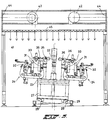
- Figs. 2 and 3 show the device according to the invention which forms part of the device shown in Fig. 1.
- the device according to the invention comprises a co-extrusion unit 21 with a co-extrusion head 22, a turntable 23 which is essentially rotatable about a vertical shaft, and on which a number of individual moulding units 24 are detachably mounted, a removal and inspection conveyor 25, and a cooling conveyor 26.
- the turntable 23 is disposed in such a way that each moulding unit 24 can move past the co-extrusion head 22.
- Each moulding unit 24 comprises two mould halves 31, which in the closed state enclose a mould cavity, the wall of which is the shape of the container to be formed, means 32 for moving the mould halves 31 apart and together and for holding them pressed against each other with force during the blowing of a container, a blowing head 33, valves (not shown) for regulating the air feed and discharge to and from the blowing head, and a removal arm (not shown) for removing a finished container from the mould and placing it on the removal and inspection conveyor 25.
- the device works as follows.
- the open mould halves 31 of a moulding unit 24 are placed around an end section of the tube coming out of co-extrusion head 22 and are then closed.
- the bottom side of this end section of the tube is cut off by the mould halves 31 and simultaneously pinched shut, and the end section of the tube is cut off at the top side by a cutter moving past the co-extrusion head 22.
- a blow hole is thereby formed at the top side of the parison thus formed.
- the parison is thus the shape of a hollow cylinder which is closed at the bottom side and open at the top side.
- the turntable 23 turns further, and the blowing head 33 of the moulding unit 24 is placed on the blow hole of the parison.
- Air is then blown through the blowing head 33 into the parison, as a result of which the parison is blown up and pressed against the wall of the mould cavity of the mould.
- the mould is then cooled, so that the wall of the container formed hardens.
- the above-mentioned valves which are connected to the air channel leading to the blowing head 33, ensure that the pressure in the container formed is released and a controlled vacuum is then created in the container.
- the blow hole is preferably hermetically sealed by pinching together the wall parts of the container surrounding the blow hole, preferably when the not yet cooled wall parts are still in thermoplastic state, so that for sealing the blow hole additional heating is not necessary.
- the mould is opened again and the removal arm takes the ready container out of the mould and places it on the conveyor 25, as shown in Fig. 2 by arrow 34.
- each moulding unit 24 is designed as a separate unit and is mounted detachably on the turntable 23, the device according to the invention is very flexible. Different containers can be blown by fitting different moulding units 24 on the turntable 23. The moulding units 24 can be changed quickly. The pipes connected to the moulding units 24 must be connected to a central feed unit.
- the turntable 23 is designed in such a way that each moulding unit 24 can be fitted in any desired angular position on the turntable 23.
- the turntable 23 is therefore preferably round. From the rotation of the turntable 23 it is possible to derive a signal which indicates the orientation of the turntable, and thus the position of each moulding unit 24.
- This signal can be used for controlling various functions, for example closing mould, blowing, unloading, applying vacuum, opening mould, removing bottle.
- a desired number of moulding units 24, possibly for different types of bottles, can be placed on the turntable 23.
- Each moulding unit 24 can be placed slightly slanting on the turntable 23. This is important in the case of higher capacities, thus at higher speeds of the moulding unit 24 relative to the extrusion head 22.
- the bottom side of the tube coming out of the extrusion head 22 will be clamped first before the top side is clamped.
- Placing each moulding unit and thus each mould sloping slightly backwards on the turntable 23, viewed in the direction of rotation of the turntable 23, means that the top side of the parison formed from the tube is also clamped centrally in the mould, but at a slightly later stage than the bottom side.
- the turntable 23 is also possible to place the turntable 23 with the moulding units 24 on it as a whole slanting relative to the vertical, in such a way that at the place where the moulding units 24 pass the extrusion head 22 the moulds slope backward slightly, viewed in the direction of rotation of the turntable 23.
- the turntable 23 is mounted on an underframe 27 resting by means of rollers 28 on a base 29.
- Each moulding unit 24 is constructed and placed on the turntable 23 in such a way that the movement of the movable parts of each moulding unit takes place essentially in the radial direction of the turntable 23.
- the moulding units 24 can therefore be made relatively narrow, so that as many moulding units 24 as possible can be placed on the periphery of the turntable 23.
- one of the mould halves 31 is movable by the devices 32 in the radial direction of the turntable 23.
- the blowing head 33 is fixed to an arm 36 which can be swivelled in a vertical radial plane about a hinge point 35.
- the co-extrusion unit 21, and in particular the co-extrusion head 22 is movable in the vertical direction relative to the moulding units 24, in particular the moulds, in such a way that after cutting off of the parison from the tube coming out of the co-extrusion head 22 the co-extrusion unit 21 is moved up and then moved down again shortly after the passing of a mould, so that the co-extrusion unit 21 is at the original height again during the filling of the next mould with a parison.
- the reason for this vertical movability of the co-extrusion unit 21 is that the tube streams continuously out of the co-extrusion head 22. If the parison is cut off, the bottom side of the tube can be carried along by the mould just filled.
- this unit 21 is fitted on a frame 37 which is movable in the vertical direction (see Fig. 2).
- the frame 37 can be movable as a whole in the vertical direction, but it is also possible to make the frame pivot about a horizontal axis 38 which is situated at the side of the frame 37 away from the turntable 23.
- the frame 37 can be moved in the vertical direction by any known device, such as a hydraulic cylinder and the like.
- the containers are made of a plastic which has such a processing temperature that during the formation of the plastic tube all bacteria present in the plastic are destroyed.
- the plastic used is polyethylene (HDPE) which has a processing temperature of 200 to 220°C.
- the co-extrusion unit 21, and in particular the co-extrusion head 22, is to this end provided with means for blowing in sterile air.
- sterile air is blown over the parison at a rate of, for example, 0.4 - 0.5 m/sec. Suitable means are present for this.
- the parison is blown up in the mould with particularly sterile air.
- the sterile air is obtained by conveying air through a number of filters, first through a number of dust filters placed in series, which range from coarse to fine, and by means of which coarse dust particles are removed from the air first, and a bacteria filter by means of which any bacteria still present are removed from the air.
- the device - and in particular the channels and filters through which the sterile air is fed in - is pre-sterilised, preferably using an atomized disinfectant, in particular hydrogen peroxide.
- the whole device is accommodated in an essentially closed room 41.
- Fans 42 which blow sterile air into the room 41 are fitted at the top side of room 41.
- This air comes from a pre-sterilisation system and an air filtering unit, which is indicated by reference number 43 in Fig. 2.
- the air blown out by the fan 42 is also conveyed through a filter 45 fitted in the top of the room 41, as a result of which in the end sterile air reaches the room 41. It is also ensured that the incoming stream of air is essentially laminar.
- the blow hole can be hermetically sealed after blowing and cooling of the container by pinching together the wall parts surrounding the blow hole.
Landscapes
- Engineering & Computer Science (AREA)
- Manufacturing & Machinery (AREA)
- Mechanical Engineering (AREA)
- Blow-Moulding Or Thermoforming Of Plastics Or The Like (AREA)
Applications Claiming Priority (2)
| Application Number | Priority Date | Filing Date | Title |
|---|---|---|---|
| NL9001504A NL9001504A (nl) | 1990-07-02 | 1990-07-02 | Werkwijze en inrichting voor het vervaardigen van kunststofhouders, zoals flessen, met een uit meerdere lagen bestaande wand. |
| NL9001504 | 1990-07-02 |
Publications (2)
| Publication Number | Publication Date |
|---|---|
| EP0464933A2 true EP0464933A2 (fr) | 1992-01-08 |
| EP0464933A3 EP0464933A3 (en) | 1992-04-01 |
Family
ID=19857347
Family Applications (1)
| Application Number | Title | Priority Date | Filing Date |
|---|---|---|---|
| EP19910201660 Withdrawn EP0464933A3 (en) | 1990-07-02 | 1991-06-27 | Device and method for the manufacture of plastic containers, such as bottles, with a wall consisting of several layers |
Country Status (2)
| Country | Link |
|---|---|
| EP (1) | EP0464933A3 (fr) |
| NL (1) | NL9001504A (fr) |
Cited By (9)
| Publication number | Priority date | Publication date | Assignee | Title |
|---|---|---|---|---|
| FR2766121A1 (fr) * | 1997-07-18 | 1999-01-22 | Sidel Sa | Procede pour la fabrication de recipients steriles, et installation pour la mise en oeuvre |
| EP1002635A3 (fr) * | 1998-11-17 | 2001-05-09 | Pechiney Plastic Packaging, Inc. | Contrôle de l'extrusion d'une paraison en fonction du moule de soufflage utilisé |
| US6811390B1 (en) * | 1999-09-29 | 2004-11-02 | Sidel | Rotary extrusion-blow moulding machine with tilting moulds |
| US7396225B2 (en) * | 2003-05-23 | 2008-07-08 | Bernd Hansen | Device for blow moulding, filling and closing plastic containers |
| US20100272844A1 (en) * | 2009-04-28 | 2010-10-28 | Gea Procomac S.P.A. | Apparatus for molding containers obtained from parisons |
| US7938639B2 (en) * | 2007-04-20 | 2011-05-10 | Sidel Participations | Installation for the manufacture of containers comprising a secure enclosure provided with a system for the insufflation of filtered air |
| EP2412513A1 (fr) * | 2010-07-29 | 2012-02-01 | Gea Procomac S.p.A. | Appareil pour mouler des récipients par soufflage |
| US9056146B2 (en) | 2007-04-13 | 2015-06-16 | Khs Gmbh | Method of treating the inside surfaces of a clean room and treating a rotary beverage bottle blow-molding arrangement and blow-molding beverage bottles from preforms and an arrangement for performing the method |
| EP3666497A1 (fr) * | 2018-12-13 | 2020-06-17 | Sidel Participations | Installation de remplissage et procédé de production et de remplissage de bouteilles avec un produit coulant |
Family Cites Families (9)
| Publication number | Priority date | Publication date | Assignee | Title |
|---|---|---|---|---|
| US2952034A (en) * | 1956-04-18 | 1960-09-13 | Plax Corp | Blow molding machine and process |
| BE628760A (fr) * | 1962-02-24 | 1900-01-01 | ||
| FR87759E (fr) * | 1963-08-29 | 1966-10-07 | Solvay | Machine rotative automatique pour le soufflage de corps creux, en particulier de bouteilles, en matière thermoplastique |
| FR1404922A (fr) * | 1963-08-29 | 1965-07-02 | Solvay | Machine rotative automatique pour le soufflage de corps creux en particulier de bouteilles, en matière thermoplastique |
| OA00221A (fr) * | 1963-11-21 | 1966-03-15 | Settembrini Antoine Di | Machine pour la fabrication de récipients en matières plastiques. |
| ES344708A1 (es) * | 1966-09-29 | 1968-10-16 | Solvay | Maquina rotativa continua para el moldeo de cuerpos huuecosde materia termoplastica. |
| US3496600A (en) * | 1967-04-03 | 1970-02-24 | Nrm Corp | Blow molding machine |
| US4208852A (en) * | 1974-11-08 | 1980-06-24 | Pont-A-Mousson S.A. | Process for the aseptic packing of products and machine employing said process |
| CA1252967A (fr) * | 1987-03-23 | 1989-04-25 | Paul M. Oles | Machine tournante de moulage par soufflage |
-
1990
- 1990-07-02 NL NL9001504A patent/NL9001504A/nl not_active Application Discontinuation
-
1991
- 1991-06-27 EP EP19910201660 patent/EP0464933A3/en not_active Withdrawn
Cited By (15)
| Publication number | Priority date | Publication date | Assignee | Title |
|---|---|---|---|---|
| FR2766121A1 (fr) * | 1997-07-18 | 1999-01-22 | Sidel Sa | Procede pour la fabrication de recipients steriles, et installation pour la mise en oeuvre |
| WO1999003667A1 (fr) * | 1997-07-18 | 1999-01-28 | Sidel S.A. | Procede pour la fabrication de recipients steriles en matiere plastique, et installation pour la mise en oeuvre |
| CN1081531C (zh) * | 1997-07-18 | 2002-03-27 | 西德尔公司 | 塑料无菌容器的制造方法及其实施设备 |
| US6562281B1 (en) | 1997-07-18 | 2003-05-13 | Sidel | Method for making sterilized plastic containers, and installation therefor |
| EP1002635A3 (fr) * | 1998-11-17 | 2001-05-09 | Pechiney Plastic Packaging, Inc. | Contrôle de l'extrusion d'une paraison en fonction du moule de soufflage utilisé |
| US6345973B1 (en) | 1998-11-17 | 2002-02-12 | Pechiney Emballage Flexible Europe | Multiple in-line parison control |
| US6811390B1 (en) * | 1999-09-29 | 2004-11-02 | Sidel | Rotary extrusion-blow moulding machine with tilting moulds |
| US7396225B2 (en) * | 2003-05-23 | 2008-07-08 | Bernd Hansen | Device for blow moulding, filling and closing plastic containers |
| US9056146B2 (en) | 2007-04-13 | 2015-06-16 | Khs Gmbh | Method of treating the inside surfaces of a clean room and treating a rotary beverage bottle blow-molding arrangement and blow-molding beverage bottles from preforms and an arrangement for performing the method |
| US7938639B2 (en) * | 2007-04-20 | 2011-05-10 | Sidel Participations | Installation for the manufacture of containers comprising a secure enclosure provided with a system for the insufflation of filtered air |
| US20100272844A1 (en) * | 2009-04-28 | 2010-10-28 | Gea Procomac S.P.A. | Apparatus for molding containers obtained from parisons |
| US8197245B2 (en) * | 2009-04-28 | 2012-06-12 | Gea Procomac S.P.A. | Apparatus for molding containers obtained from parisons |
| EP2412513A1 (fr) * | 2010-07-29 | 2012-02-01 | Gea Procomac S.p.A. | Appareil pour mouler des récipients par soufflage |
| EP3666497A1 (fr) * | 2018-12-13 | 2020-06-17 | Sidel Participations | Installation de remplissage et procédé de production et de remplissage de bouteilles avec un produit coulant |
| WO2020120101A1 (fr) * | 2018-12-13 | 2020-06-18 | Sidel Participations | Installation de remplissage et procédé de production de bouteilles et de remplissage de bouteilles avec un produit coulant |
Also Published As
| Publication number | Publication date |
|---|---|
| EP0464933A3 (en) | 1992-04-01 |
| NL9001504A (nl) | 1992-02-03 |
Similar Documents
| Publication | Publication Date | Title |
|---|---|---|
| US5669208A (en) | Packaging | |
| CN100406350C (zh) | 制造设备 | |
| US6692684B1 (en) | Method and apparatus for producing a sterile packaging container | |
| US4707966A (en) | Container with an encapsulated top insert and method and apparatus for making same | |
| JP3950053B2 (ja) | 容器の製造および充填のための方法ならびに装置 | |
| EP0464933A2 (fr) | Dispositif et procédé pour la fabrication de récipients en matière plastique, tels que bouteilles, avec parois multi-couches | |
| GB1248608A (en) | A machine for the production, filling and closing of a plastics container and a method of sterilising the machine | |
| JP2007508214A (ja) | 媒体で充填された少なくとも1つの容器を形成する方法および装置 | |
| KR20180063158A (ko) | 컨테이너 제품들의 미생물학적 오염물들을 감소시키기 위한 디바이스 | |
| US20210122099A1 (en) | Sterilizable blowing air paths and stretching rod of a blow moulding machine | |
| CN100453407C (zh) | 制造和装灌容器的方法和设备 | |
| EP1868787B1 (fr) | Appareil de transfert de doses | |
| CN111844692A (zh) | 一种塑料瓶连续生产灌装设备 | |
| CN212707950U (zh) | 一种塑料瓶生产灌装设备 | |
| US8277211B2 (en) | Apparatus for transferring doses and dose | |
| GB1590612A (en) | Method and apparatus for the production by blow-moulding of hollow plastics articles which are closed and sterile | |
| US3328837A (en) | Blow-molding apparatus | |
| US3327035A (en) | Method and machines for making bottles and other hollow articles | |
| MX2007012845A (es) | Aparato para transferir porciones y porcion. | |
| JPS63297024A (ja) | ロ−タリ−式同時成形充填方法及び装置 | |
| WO1997026126A1 (fr) | Procede et dispositif de moulage par soufflage, de remplissage, et de fermeture de flacon a boisson | |
| MXPA05011698A (es) | Embalaje de aceleracion de rueda de moldeo por soplado. | |
| JPH10180854A (ja) | 中空成形機による成形品の製造方法および装置 | |
| JP2674774B2 (ja) | 合成樹脂製の無菌容器及びその製造方法 | |
| JP2005008243A (ja) | 無菌充填用ブロー成形容器およびその殺菌方法 |
Legal Events
| Date | Code | Title | Description |
|---|---|---|---|
| PUAI | Public reference made under article 153(3) epc to a published international application that has entered the european phase |
Free format text: ORIGINAL CODE: 0009012 |
|
| AK | Designated contracting states |
Kind code of ref document: A2 Designated state(s): AT BE CH DE DK ES FR GB GR IT LI LU NL SE |
|
| PUAL | Search report despatched |
Free format text: ORIGINAL CODE: 0009013 |
|
| AK | Designated contracting states |
Kind code of ref document: A3 Designated state(s): AT BE CH DE DK ES FR GB GR IT LI LU NL SE |
|
| 17P | Request for examination filed |
Effective date: 19921001 |
|
| 17Q | First examination report despatched |
Effective date: 19931123 |
|
| STAA | Information on the status of an ep patent application or granted ep patent |
Free format text: STATUS: THE APPLICATION IS DEEMED TO BE WITHDRAWN |
|
| 18D | Application deemed to be withdrawn |
Effective date: 19940205 |