EP0464950B1 - Dispositif pour véhicule de ramassage d'ordures destiné à lever et vider des récipients - Google Patents
Dispositif pour véhicule de ramassage d'ordures destiné à lever et vider des récipients Download PDFInfo
- Publication number
- EP0464950B1 EP0464950B1 EP91201698A EP91201698A EP0464950B1 EP 0464950 B1 EP0464950 B1 EP 0464950B1 EP 91201698 A EP91201698 A EP 91201698A EP 91201698 A EP91201698 A EP 91201698A EP 0464950 B1 EP0464950 B1 EP 0464950B1
- Authority
- EP
- European Patent Office
- Prior art keywords
- pick
- endless carrier
- members
- container
- tilting
- Prior art date
- Legal status (The legal status is an assumption and is not a legal conclusion. Google has not performed a legal analysis and makes no representation as to the accuracy of the status listed.)
- Expired - Lifetime
Links
- 238000004140 cleaning Methods 0.000 claims description 20
- 239000007788 liquid Substances 0.000 claims description 11
- 239000007921 spray Substances 0.000 claims description 5
- 238000010276 construction Methods 0.000 description 2
- 238000000926 separation method Methods 0.000 description 2
- 239000004677 Nylon Substances 0.000 description 1
- 239000000969 carrier Substances 0.000 description 1
- 239000003086 colorant Substances 0.000 description 1
- 230000008878 coupling Effects 0.000 description 1
- 238000010168 coupling process Methods 0.000 description 1
- 238000005859 coupling reaction Methods 0.000 description 1
- 230000007613 environmental effect Effects 0.000 description 1
- 238000000034 method Methods 0.000 description 1
- 229920001778 nylon Polymers 0.000 description 1
- 239000000725 suspension Substances 0.000 description 1
Images




Classifications
-
- B—PERFORMING OPERATIONS; TRANSPORTING
- B65—CONVEYING; PACKING; STORING; HANDLING THIN OR FILAMENTARY MATERIAL
- B65F—GATHERING OR REMOVAL OF DOMESTIC OR LIKE REFUSE
- B65F3/00—Vehicles particularly adapted for collecting refuse
- B65F3/02—Vehicles particularly adapted for collecting refuse with means for discharging refuse receptacles thereinto
- B65F3/08—Platform elevators or hoists with guides or runways for raising or tipping receptacles
-
- B—PERFORMING OPERATIONS; TRANSPORTING
- B65—CONVEYING; PACKING; STORING; HANDLING THIN OR FILAMENTARY MATERIAL
- B65F—GATHERING OR REMOVAL OF DOMESTIC OR LIKE REFUSE
- B65F7/00—Cleaning or disinfecting devices combined with refuse receptacles or refuse vehicles
- B65F7/005—Devices, mounted on refuse collecting vehicles, for cleaning or disinfecting refuse receptacles
Definitions
- the invention relates to a loading and emptying device for a refuse vehicle comprising an endless carrier, running in a substantially vertical plane, one or more pick up members attached to the endless carrier and tilting means for tilting a container.
- Such a device is known from the German Patent 432.470.
- This known device has an endless carrier, consisting of two parallel chains, running in the longitudinal direction around the body of a refuse vehicle. Pairs of T- or U- shaped hooks are fixedly connected to the chains, which serve as pick up members for refuse containers.
- a refuse container with a rod extending at both sides, is placed on a raised platform at the back of the refuse vehicle with the extending parts of the rod close to the endless carrier. The next pair of hooks pick up the container and transport it along the path of the endless carrier.
- the container is brought into an inverted position by putting it over a steep bulge, whereby immediately after passing the top of the bulge it lands on a spring supported plate, in order to prevent it from falling out of the hooks.
- the container After passing the refuse collecting compartment of the vehicle the container reaches the downwardly directed part of the path of the endless carrier, where it falls out of the hooks and with the extending parts of the rod into a pair of arc shaped guides upwardly directed, where it returns to its starting position.
- the pick up member consisting of a pair of hooks
- the endless carrier so that in order to tilt the container, the container has also to be repositioned relative to the pick up member.
- the freedom of movement of the container is restrained by the chains of the endless carrier as a result of which the container has to be dropped out of the hooks in order to get it back to its starting position.
- the container returns to its starting position at the front of the refuse vehicle. Because controlling the movement of the container requires a lot of space, tilting it through an angle of 180° and back again over the same angle; this known device is not suited to be placed at for instance the backside of a refuse vehicle.
- the pick up member or pick up members are rotatably mounted on an attachment member or members, attaching the pick up member or members to the endless carrier by means of said attachment member or members, the axis of rotation being perpendicular to the plane of the endless carrier and the endless carrier having two horizontal parts and two vertical parts, and in that the tilting means consist of rolls on the pick up member or members and bosses and/or guides on the device, cooperating with said rolls, whereby the pick up member or members rotate through an angle of 180° or more at the angular points between the upper horizontal part and the two vertical parts and/or along the beginning and end of the upper horizontal part, the pickup member or members turning through an angle of 360° along the path of the endless carrier.
- the container reaches its inverted position at the upper horizontal part of the path where it is emptied in a receiving member of the refuse vehicle. Because the container is tilted in two controlled steps through an angle of 360°, in order to empty the container and to bring it back in its starting position, the space needed for the device can be small enough to be able to locate the device at the backside of the refuse vehicle.
- a container loading device is known with two parallel endless chains and a pick up member with U-shaped hooks connected to each other by a beam.
- the hooks are to engage support means of a container which can be secured in the hooks.
- the container goes upwardly to an inverted position and back to its starting position along the same path.
- the tilting means consists of a boss in each of the corners between the upper horizontal and the two vertical parts of the path of the endless carrier and two rolls mounted on the pick up member on either side of the pivot point thereof, whereby the respective rolls engage the respective bosses with the movement of the pick up member through the upper bends of the path of the endless carrier.
- the lower horizontal part of the path of the endless carrier is mounted at such a height, that there the pick up member is no longer in engagement with the container.
- a container is picked up at the beginning of a vertical part of the path of the endless carrier where guides may be mounted to guide the container to the right position and is put back at the end of the other vertical part of the path, because the container touches the ground before the pick up member reaches the lower horizontal part of the path.
- the container Shortly after the container is picked up it is secured to the pick up member, for instance with a clamp over the pick up cam.
- the clamp is put into and out position when it passes certain points along the path of the endless carrier, which is a system known per se with refuse container loading devices.
- a receiving member is provided, which is mounted beneath the upper horizontal part of the path of the pick up member and which is in downward direction at least partly funnel-shaped.
- the receiving member extends from one side of the loading device to the other side thereof, where it connects to the usual receiving section of the refuse vehicle.
- the invention provides that at the upper bends in the path of the endless carrier guides for a cover of the container are mounted, extending from where the tilting starts to outside of the receiving member.With these guides the cover of the container is guided from a closed position to a totally opened position and back to a closed position before reaching the next tilting phase of 180°.
- These guides also enable to operate the device in a clockwise direction as well as in a anti-clockwise direction.
- the tilting means consists of rolls on the pick up member, one at either side of its pivot point, a protruding part of the pick up member at a distance from the pivot point parallel to the pivot axis of the pick up member, which lies against the endless carrier along the vertical parts of the path thereof, and guides for the rolls and the protruding part of the pick up member which are mounted symmetrically with a vertical plane of symmetry intersecting the plane of the endless carrier perpendicular in the middle, whereby the guides for the protruding part are destined to tilt the pick up member from a normal or tilted position to an overturned position or vice versa and the guides for the rolls to tilt the pick up member from an overturned position to an inverted position or vice versa.
- the top of the container is already above the receiving member when the container is only just slightly tilted, so that the danger exists of refuse dropping besides the receiving member.
- further supporting means consisting of a roll between the pick up member and the endless carrier, rotatable around the pivot axis of the pick up member, a supporting beam therefor and an U-shaped guideway for the end of the attachment member or members, protruding at the other side of the endless carrier, the supporting beam and the U-shaped guideway extending at least along the greater part of the upper horizontal part of the path of the endless carrier.
- the invention also provides that the wall of the receiving member has at least one detachable part.
- the wall of the receiving member has at least one detachable part.
- a first possibility is to mount two loading devices next to each other, whereby each receiving member connects to its own compartment of the refuse vehicle.
- the number of pick up members per loading device have to be taken into account, and also a coupling between the two endless carriers of the devices has to be made, in order to let the different containers pass each other safely.
- Another possibility is to provide a movable slide in the receiving member, which is suited for a system with a vertical separation or a system with a horizontal separation with control means to bring the movable slide in the correct position for each container.
- a simple embodiment hereof is a manual operated control system with control means in different colours corresponding to the colour of the different containers.
- the invention also provides in a cleaning device for containers which comprises a reservoir for a cleaning liquid, a number of spray nozzles directed upwardly, means to spray under pressure the cleaning liquid and receptacle for the used cleaning liquid.
- This cleaning device can be put through the detachable part or parts in the wall of the receiving member into the receiving member and partly into the refuse vehicle.
- the cleaning device according to the invention means a considerable improvement, which will meet the environmental demands to be expected in the future.
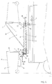
- a refuse vehicle is indicated with 1 whereto a framework 2 with an interposed framework 3 is mounted.
- sprocket wheels 4,5,6,7 are mounted, around which an endless chain is put, whereby one of the sprocket wheels, in the drawn example sprocket wheel 5, is provided with a driving member, which can be an hydraulic motor.
- One or more pick up members 10 are attached to the chain 8. In fig. 1 one pick up member is indicated, but a framework of that size will operate in most cases at its best with four pick up members.
- the pick up member 10 is attached to chain 8 in such a way, that the pick up member can move with respect to the chain parallel to plane wherein the chain 8 lies.
- the pick up member 10 pivots about a shaft 17, located at some distance from the chain 8.
- the pick up member 10 has a pick up cam 11 at some distance of the plane wherein the chain 8 lies, intended to engage the pick up strip 12 of a container 13, whereby also a support arm 14 is provided, which abuts against the side of the container 13 when the container 13 is taken along with the pick up member 10.
- the pick up member has tilting rolls 15,16, which are mounted at each side and at the same distance of the pivot axis 17 of the pick member 10.
- the tilting rolls 15,16 are intended to cooperate with tilting bosses 18,19 mounted on the sprocket wheels 4,5, whereby tilting roll 15 engages with boss 19 and tilting roll 16 engages with boss 18. Regardless whether the endless chain 8 runs in a clockwise or anti-clockwise direction.
- a tilting roll 15,16 engages a tilting boss 18,19 and the tilting movement is started with the further movement of the chain 8.
- a guide 20 for the tilting rolls 15,16 is mounted, which has a lower course near the tilting bosses 18,19 than in the central part of the guide 20 where the pick up member is moved in a vertical position.
- the receiving member is indicated with 27, which is more of less funnel-shaped, seen from the back as well as from aside, and connects to the usual receiving space in the refuse vehicle.
- doors 28 are mounted, through which other refuse then offered in containers, can be brought into the receiving space of the refuse vehicle without much effort.
- the two guides 21,22 are indicated, which support the housing 23 of the container 13 with the guide 21 being mounted on the edge of the receiving member 27.
- the guides 21,22 engage the rims of the housing 23 of the container 13 at the moment the tilting movement starts.
- a guide for the cover 26 of the container is provided, which is mounted near the upper corner point between the guides 21,22 for the housing 23 of the container.
- the cover 26 also engages this guide at the moment that the tilting movement starts.
- the guide runs obliquely downwards at the position where the container is entirely above the receiving member, so that the cover may pivot open.
- the cover runs along an identical guide only in opposite direction as a result of which the cover closes again.
- the guide may be formed from a part of the sidewall of the receiving member, that runs sufficiently oblique in the direction of transport.
- Fig. 4 shows another embodiment of the device according to the invention.
- the endless carrier consists of two endless chains 8,8', which run over sprocket wheels 4,4',5,5',6,6',7,7'.
- the pick up member 10 is attached to the two chains 8,8' by means of an attachment member 29, which also fixedly connects the two chains to each other.
- the combination of two chains 8,8', pairs of sprocket wheels and an attachment member 29 that connects the chain, ensure a very stable suspension and pivot point for the pick up member 10.
- the pick up member 10 further comprises a mounting plate 32, rolls 30,31, an extension part 33, in fig. 4 downwardly directed, and a protruding arm 34.
- the parts 11,14,32,33,34 form a rigid construction which is pivotable around the protruding part of the attachment member 29.
- the rolls 30 and 31 are mounted at each side of the mounting plate 32. These rolls 30,31 and the protruding arm 34, which is located at the opposite side of the pivot point with respect to the rolls 30,31, form together with the guides 35-38 inclusive the tilting means for the pick up member 10.
- the protruding arm 34 extends parallel to the pivot axis till near the chain 8' in the rear. During the vertical parts of the path of the endless carrier the protruding arm 34 abuts against chain 8. Near the upper corner points guideways 35,38 are mounted for the protruding arm 34. The lower ends of these guideways are partly located between the sprocket wheels 4,4' and 5,5'.
- Fig. 5 shows schematically the movements of the pick up member along the path of the endless carrier.
- the tilting movement starts when the attachment member 29 reaches the upper sprocket wheel 4 or 5, where the vertical movement changes in a horizontal movement along the path of the chains, while the protruding arm continues the vertical movement, lying against the vertical part of chain 8.
- the protruding arm 38 also prevents the pick up member 10 with the container 13 from swaying against the receiving member 27.
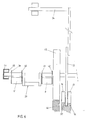
- Fig. 6 shows schematically a side view of the pick up member 10 in an inverted position, without the pick up cam 11 and the supporting arm 14.
- the attachment member 29 is fixedly connected to the chains 8, 8' by means of plates 39-42. To one end of the attachment member 29, at the left side in the drawing, a roller 43 is fitted, which runs in a U-shaped runway 44.
- a roller 47 is fitted to the protruding arm 34, made of nylon for example, which is to run in the guideways 35, 38.
- the attachment member 29 has the shape of a crankshaft, with the crank located between the two chains 8, 8'. This construction prevents the attachment member from engaging the guides 35, 38 for the protruding arm 34.
- fig. 7 shows the device according to the invention with a cleaning device mounted in the receiving member 27, so that the refuse vehicle may now be used as a cleaning device for containers.
- the cleaning device which can be mounted after the door or doors 28 are removed from the receiving member 27, comprises a reservoir 24 for a cleaning liquid, a receptacle 25 to receive used liquid and a pump 50 to wash out the containers with cleaning liquid through one or more spray nozzles 51.
- a grid 52 may be mounted above the receptacle 25 for used cleaning liquid to retain possible residual refuse from the containers.
Landscapes
- Engineering & Computer Science (AREA)
- Mechanical Engineering (AREA)
- Refuse-Collection Vehicles (AREA)
- Forklifts And Lifting Vehicles (AREA)
- Refuse Collection And Transfer (AREA)
Claims (11)
- Dispositif pour véhicule de ramassage d'ordures destiné à lever et vider des récipients comprenant un transporteur sans fin se déplaçant dans un plan sensiblement vertical, un ou plusieurs éléments d'accrochage fixés au transporteur sans fin et des moyens d'inclinaison pour incliner un récipient, caractérisé en ce que le ou les éléments d'accrochage (10) sont montés en rotation sur un ou des éléments de fixation (29) reliant le ou les éléments d'accrochage (10) au transporteur sans fin (8, 8') au moyen du ou desdits éléments de fixation l'axe de rotation étant perpendiculaire au plan du transporteur sans fin et le transporteur sans fin comportant deux parties horizontales et deux parties verticales, et en ce que les éléments d'inclinaison comprennent des rouleaux sur le ou les éléments d'accrochage (10) et des bossages et/ou des guides sur le dispositif en coopération avec lesdits rouleaux, de façon que le ou les éléments d'accrochage (10) tournent d'un angle de 180° ou davantage aux points angulaires entre la partie horizontale supérieure et les deux parties verticales ou le long de tronçons comprenant un point angulaire et une portion de la partie horizontale supérieure du trajet adjacente à ce point angulaire, le ou les éléments d'accrochage effectuant une rotation de 360° le long du trajet du transporteur sans fin.
- Dispositif selon la revendication 1, caractérisé en ce qu'un élément receveur (27) d'ordures traverse le dispositif d'un côté ou de l'autre, pénètre dans le véhicule et a, au moins en partie, la forme d'un entonnoir.
- Dispositif selon l'une des revendications 1 ou 2, caractérisé en ce que les moyens d'inclinaison comprennent un bossage (18, 19) dans chacun des virages entre la partie horizontale supérieure et les deux parties verticales du trajet du transporteur sans fin (8, 8') et deux rouleaux (15, 16) montés sur l'élément d'accrochage (10) d'un côté ou de l'autre de son point de pivotement, de façon que les rouleaux respectifs (15, 16) viennent en prise avec les bossages respectifs (18, 19) grâce au mouvement de l'élément d'accrochage (10) sur les coudes supérieurs du trajet du transporteur sans fin (8, 8').
- Dispositif selon la revendication 3, caractérisé en ce qu'entre les bossages (18, 19) est monté un guide des rouleaux (15, 16) sur le ou les éléments d'accrochage (10).
- Dispositif selon la revendication 3 ou 4, caractérisé en ce que deux guides parallèles (21, 22) de récipient sont installés entre le point où commence l'inclinaison et le point où s'achève l'inclinaison.
- Dispositif selon l'une des revendications 3, 4 ou 5, caractérisé en ce que sur les coudes supérieurs du trajet du transporteur sans fin (8, 8') sont montés des guides pour couvercle (26) du récipient (13), qui s'étendent entre le point où commence l'inclinaison et l'extérieur de l'élément receveur (27).
- Dispositif selon la revendication 1 ou 2, caractérisé en ce que les moyens d'inclinaison comprennent des rouleaux (30, 31) montés sur l'élément d'accrochage (10), dont l'un se trouve d'un côté ou de l'autre de son point de pivotement, une partie en saillie (34) de l'élément d'accrochage (10) à une certaine distance du point de pivotement, parallèle à l'axe de pivotement de l'élément d'accorchage (10), qui se situe contre le transporteur sans fin (8, 8') le long des parties verticales du trajet de ce dernier, et des guides (36, 37) pour les rouleaux (30, 31) et la partie en saillie (34) de l'élément d'accrochage (10) qui sont montés de manière symétrique et dont le plan de symmétrie vertical coupe le plan du transporteur sans fin (8, 8') perpendiculairement au milieu, de sorte que les guides (35, 38) de la partie en saillie sont destinés à incliner l'élément d'accrochage (10) entre une position normale ou inclinée et une position retournée ou inversement et les guides (36, 37) des rouleaux (30, 31) sont destinés à incliner l'élément d'accrochage (10) entre une position retournée et une position inversée ou inversement.
- Dispositif selon la revendication 7, caractérisé en ce qu'il comprend en outre des moyens supports comportant un rouleau (45) entre l'élément d'accrochage (10) et le transporteur sans fin (8, 8'), rotatif autour de l'axe de pivotement de l'élément d'accrochage (10), un élément support (46) pour ce rouleau et une voie de guidage en "U" (44) pour l'extrémité du ou des éléments d'accrochage (10) faisant saillie de l'autre côté du transporteur sans fin (8, 8'), le bras support (46) et la voie de guidage en "U" (44) s'étendant au moins le long de la majeure partie de la partie horizontale supérieure du trajet du transporteur sans fin (8, 8').
- Dispositif selon l'une ou plusieurs des revendications précédentes, caractérisé en ce que le transporteur sans fin (8, 8') se compose de deux chaînes sans fin (8, 8') circulant dans des plans parallèles, et reliées entre elles par la ou les parties en saillie du ou des éléments de fixation (29).
- Dispositif selon la revendication 2, caractérisé en ce que la paroi de l'élément receveur (27) comprend au moins une partie détachable (28).
- Dispositif de nettoyage de récipients comprenant un dispositif selon l'une ou plusieurs des revendications précédentes, caractérisé en ce qu'il comprend en outre un réservoir (24) de liquide de nettoyage, un certain nombre de buses de pulvérisation (51) orientées vers le haut, des moyens (50) de vaporisation sous pression du liquide de nettoyage, un réceptacle (25) destiné à recevoir le liquide de nettoyage usé, et en ce que le dispositif se monte dans l'élément receveur (27) à travers la partie détachable (28) de ce dernier.
Applications Claiming Priority (2)
| Application Number | Priority Date | Filing Date | Title |
|---|---|---|---|
| NL9001533A NL9001533A (nl) | 1990-07-05 | 1990-07-05 | Beladingsinstallatie voor containers. |
| NL9001533 | 1990-07-05 |
Publications (2)
| Publication Number | Publication Date |
|---|---|
| EP0464950A1 EP0464950A1 (fr) | 1992-01-08 |
| EP0464950B1 true EP0464950B1 (fr) | 1993-05-12 |
Family
ID=19857368
Family Applications (1)
| Application Number | Title | Priority Date | Filing Date |
|---|---|---|---|
| EP91201698A Expired - Lifetime EP0464950B1 (fr) | 1990-07-05 | 1991-07-03 | Dispositif pour véhicule de ramassage d'ordures destiné à lever et vider des récipients |
Country Status (6)
| Country | Link |
|---|---|
| EP (1) | EP0464950B1 (fr) |
| AT (1) | ATE89230T1 (fr) |
| DE (1) | DE69100082T2 (fr) |
| DK (1) | DK0464950T3 (fr) |
| ES (1) | ES2042335T3 (fr) |
| NL (1) | NL9001533A (fr) |
Families Citing this family (3)
| Publication number | Priority date | Publication date | Assignee | Title |
|---|---|---|---|---|
| NL9201611A (nl) * | 1992-09-17 | 1994-04-18 | Vda Konst Bv | Beladingsinrichting en opneemorgaan voor beladingsinrichting, alsmede geleidingen voor het opneemorgaan. |
| US8297905B2 (en) * | 2009-10-19 | 2012-10-30 | Lindy Lawrence May | 180 degree inverting mechanism |
| CN110422637B (zh) * | 2019-08-09 | 2020-12-25 | 桐乡市桐宇环保科技有限公司 | 一种具有上料装置用具有辅助推料功能的推料机构 |
Family Cites Families (3)
| Publication number | Priority date | Publication date | Assignee | Title |
|---|---|---|---|---|
| DE432470C (de) * | 1925-09-03 | 1927-04-08 | Robert Hennecke | Muellabfuhrwagen |
| US4219298A (en) * | 1974-09-13 | 1980-08-26 | Government Innovators | Rapid rail |
| US4090626A (en) * | 1975-12-29 | 1978-05-23 | Ebeling Franklin D | Trash handling device |
-
1990
- 1990-07-05 NL NL9001533A patent/NL9001533A/nl not_active Application Discontinuation
-
1991
- 1991-07-03 AT AT91201698T patent/ATE89230T1/de not_active IP Right Cessation
- 1991-07-03 DE DE91201698T patent/DE69100082T2/de not_active Expired - Fee Related
- 1991-07-03 ES ES199191201698T patent/ES2042335T3/es not_active Expired - Lifetime
- 1991-07-03 DK DK91201698.7T patent/DK0464950T3/da active
- 1991-07-03 EP EP91201698A patent/EP0464950B1/fr not_active Expired - Lifetime
Also Published As
| Publication number | Publication date |
|---|---|
| ES2042335T3 (es) | 1993-12-01 |
| EP0464950A1 (fr) | 1992-01-08 |
| NL9001533A (nl) | 1992-02-03 |
| DK0464950T3 (da) | 1993-07-12 |
| DE69100082D1 (de) | 1993-06-17 |
| DE69100082T2 (de) | 1993-10-28 |
| ATE89230T1 (de) | 1993-05-15 |
Similar Documents
| Publication | Publication Date | Title |
|---|---|---|
| RU2195421C2 (ru) | Подъемно-опрокидывающее устройство | |
| US4840531A (en) | Vehicle for curbside collection of source separated recyclable materials | |
| US5011036A (en) | Front loading, foot operated refuse bin | |
| GB2080757A (en) | Vehicle with lateral equipment for the movement of containers in general | |
| US3576265A (en) | Material collection system | |
| IL40325A (en) | A tipper for discharging refuse containers into refuse collector | |
| EP0577540A1 (fr) | Véhicule de ramassage d'ordures | |
| CN109748015A (zh) | 一种垃圾桶提升架及其应用 | |
| EP0464950B1 (fr) | Dispositif pour véhicule de ramassage d'ordures destiné à lever et vider des récipients | |
| US20060049729A1 (en) | Book storage and transportation bin | |
| SU1440337A3 (ru) | Устройство дл отдельной или групповой автоматической выемки предметов | |
| WO1993001111A1 (fr) | Vehicule de ramassage d'elements recyclables | |
| US3262589A (en) | Refuse disposal | |
| RU2107014C1 (ru) | Подъемно-опрокидывающее или опрокидывающее устройство для опорожнения мусорных баков | |
| US5735217A (en) | Rail-type conveyor system | |
| GB2222813A (en) | Refuse collection vehicle | |
| CA1109830A (fr) | Dispositif leveur-verseur pour vider des bacs dans un compartiment recepteur, notamment pour le transfert du contenu des poubelles a un camion a ordures | |
| EP0728684A1 (fr) | Véhicule de collecte des déchets avec dispositif de ramassage latéral | |
| EP1306321B1 (fr) | Système pour la collecte des ordures | |
| US5678975A (en) | Waste container throw-in system for buildings | |
| GB2254595A (en) | Box emptying machine | |
| ATE140910T1 (de) | Behälter-hub und kippvorrichtung für müllsammelfahrzeuge | |
| SU779129A1 (ru) | Железнодорожна платформа дл перевозки грузов в емкост х | |
| JPH09278113A (ja) | 塵芥車の反転装置 | |
| CA1299530C (fr) | Vehicule pour la collecte de dechets recyclables tries et poses en bordure dela route |
Legal Events
| Date | Code | Title | Description |
|---|---|---|---|
| PUAI | Public reference made under article 153(3) epc to a published international application that has entered the european phase |
Free format text: ORIGINAL CODE: 0009012 |
|
| AK | Designated contracting states |
Kind code of ref document: A1 Designated state(s): AT BE CH DE DK ES FR GB IT LI LU NL SE |
|
| 17P | Request for examination filed |
Effective date: 19920120 |
|
| 17Q | First examination report despatched |
Effective date: 19920224 |
|
| GRAA | (expected) grant |
Free format text: ORIGINAL CODE: 0009210 |
|
| AK | Designated contracting states |
Kind code of ref document: B1 Designated state(s): AT BE CH DE DK ES FR GB IT LI LU NL SE |
|
| REF | Corresponds to: |
Ref document number: 89230 Country of ref document: AT Date of ref document: 19930515 Kind code of ref document: T |
|
| REF | Corresponds to: |
Ref document number: 69100082 Country of ref document: DE Date of ref document: 19930617 |
|
| ITF | It: translation for a ep patent filed | ||
| REG | Reference to a national code |
Ref country code: DK Ref legal event code: T3 |
|
| ET | Fr: translation filed | ||
| REG | Reference to a national code |
Ref country code: ES Ref legal event code: FG2A Ref document number: 2042335 Country of ref document: ES Kind code of ref document: T3 |
|
| EPTA | Lu: last paid annual fee | ||
| EAL | Se: european patent in force in sweden |
Ref document number: 91201698.7 |
|
| PGFP | Annual fee paid to national office [announced via postgrant information from national office to epo] |
Ref country code: GB Payment date: 19950627 Year of fee payment: 5 |
|
| PGFP | Annual fee paid to national office [announced via postgrant information from national office to epo] |
Ref country code: SE Payment date: 19950628 Year of fee payment: 5 |
|
| PGFP | Annual fee paid to national office [announced via postgrant information from national office to epo] |
Ref country code: BE Payment date: 19950630 Year of fee payment: 5 |
|
| PGFP | Annual fee paid to national office [announced via postgrant information from national office to epo] |
Ref country code: LU Payment date: 19950701 Year of fee payment: 5 |
|
| PGFP | Annual fee paid to national office [announced via postgrant information from national office to epo] |
Ref country code: ES Payment date: 19950705 Year of fee payment: 5 |
|
| PGFP | Annual fee paid to national office [announced via postgrant information from national office to epo] |
Ref country code: CH Payment date: 19950706 Year of fee payment: 5 |
|
| PGFP | Annual fee paid to national office [announced via postgrant information from national office to epo] |
Ref country code: DK Payment date: 19950721 Year of fee payment: 5 |
|
| PGFP | Annual fee paid to national office [announced via postgrant information from national office to epo] |
Ref country code: FR Payment date: 19950728 Year of fee payment: 5 |
|
| PGFP | Annual fee paid to national office [announced via postgrant information from national office to epo] |
Ref country code: AT Payment date: 19950731 Year of fee payment: 5 |
|
| PG25 | Lapsed in a contracting state [announced via postgrant information from national office to epo] |
Ref country code: LU Free format text: LAPSE BECAUSE OF NON-PAYMENT OF DUE FEES Effective date: 19960703 Ref country code: GB Effective date: 19960703 Ref country code: DK Effective date: 19960703 Ref country code: AT Effective date: 19960703 |
|
| REG | Reference to a national code |
Ref country code: DK Ref legal event code: EBP |
|
| PG25 | Lapsed in a contracting state [announced via postgrant information from national office to epo] |
Ref country code: SE Effective date: 19960704 Ref country code: ES Free format text: LAPSE BECAUSE OF THE APPLICANT RENOUNCES Effective date: 19960704 |
|
| PG25 | Lapsed in a contracting state [announced via postgrant information from national office to epo] |
Ref country code: LI Effective date: 19960731 Ref country code: CH Effective date: 19960731 Ref country code: BE Effective date: 19960731 |
|
| BERE | Be: lapsed |
Owner name: V.D.A. KONSTRUKTIES B.V. Effective date: 19960731 |
|
| GBPC | Gb: european patent ceased through non-payment of renewal fee |
Effective date: 19960703 |
|
| REG | Reference to a national code |
Ref country code: CH Ref legal event code: PL |
|
| PG25 | Lapsed in a contracting state [announced via postgrant information from national office to epo] |
Ref country code: FR Effective date: 19970328 |
|
| EUG | Se: european patent has lapsed |
Ref document number: 91201698.7 |
|
| REG | Reference to a national code |
Ref country code: FR Ref legal event code: ST |
|
| REG | Reference to a national code |
Ref country code: ES Ref legal event code: FD2A Effective date: 19991007 |
|
| PGFP | Annual fee paid to national office [announced via postgrant information from national office to epo] |
Ref country code: NL Payment date: 20020715 Year of fee payment: 12 |
|
| PGFP | Annual fee paid to national office [announced via postgrant information from national office to epo] |
Ref country code: DE Payment date: 20020726 Year of fee payment: 12 |
|
| PG25 | Lapsed in a contracting state [announced via postgrant information from national office to epo] |
Ref country code: NL Free format text: LAPSE BECAUSE OF NON-PAYMENT OF DUE FEES Effective date: 20040201 |
|
| PG25 | Lapsed in a contracting state [announced via postgrant information from national office to epo] |
Ref country code: DE Free format text: LAPSE BECAUSE OF NON-PAYMENT OF DUE FEES Effective date: 20040203 |
|
| NLV4 | Nl: lapsed or anulled due to non-payment of the annual fee |
Effective date: 20040201 |
|
| PG25 | Lapsed in a contracting state [announced via postgrant information from national office to epo] |
Ref country code: IT Free format text: LAPSE BECAUSE OF NON-PAYMENT OF DUE FEES;WARNING: LAPSES OF ITALIAN PATENTS WITH EFFECTIVE DATE BEFORE 2007 MAY HAVE OCCURRED AT ANY TIME BEFORE 2007. THE CORRECT EFFECTIVE DATE MAY BE DIFFERENT FROM THE ONE RECORDED. Effective date: 20050703 |
|
| PLBE | No opposition filed within time limit |
Free format text: ORIGINAL CODE: 0009261 |
|
| STAA | Information on the status of an ep patent application or granted ep patent |
Free format text: STATUS: NO OPPOSITION FILED WITHIN TIME LIMIT |