EP0465004B1 - Aube de turbine refroidie - Google Patents
Aube de turbine refroidie Download PDFInfo
- Publication number
- EP0465004B1 EP0465004B1 EP91304914A EP91304914A EP0465004B1 EP 0465004 B1 EP0465004 B1 EP 0465004B1 EP 91304914 A EP91304914 A EP 91304914A EP 91304914 A EP91304914 A EP 91304914A EP 0465004 B1 EP0465004 B1 EP 0465004B1
- Authority
- EP
- European Patent Office
- Prior art keywords
- aerofoil
- wall member
- passage
- bend
- blade
- Prior art date
- Legal status (The legal status is an assumption and is not a legal conclusion. Google has not performed a legal analysis and makes no representation as to the accuracy of the status listed.)
- Expired - Lifetime
Links
- 238000001816 cooling Methods 0.000 claims description 35
- 239000012809 cooling fluid Substances 0.000 claims description 12
- 238000011144 upstream manufacturing Methods 0.000 claims description 10
- 230000001154 acute effect Effects 0.000 claims description 6
- 239000012530 fluid Substances 0.000 claims description 2
- 230000000750 progressive effect Effects 0.000 claims description 2
- 239000007789 gas Substances 0.000 description 9
- 230000003068 static effect Effects 0.000 description 3
- 238000004519 manufacturing process Methods 0.000 description 2
- 230000004048 modification Effects 0.000 description 2
- 238000012986 modification Methods 0.000 description 2
- 238000005266 casting Methods 0.000 description 1
- 230000003071 parasitic effect Effects 0.000 description 1
- 230000008719 thickening Effects 0.000 description 1
Images


Classifications
-
- F—MECHANICAL ENGINEERING; LIGHTING; HEATING; WEAPONS; BLASTING
- F01—MACHINES OR ENGINES IN GENERAL; ENGINE PLANTS IN GENERAL; STEAM ENGINES
- F01D—NON-POSITIVE DISPLACEMENT MACHINES OR ENGINES, e.g. STEAM TURBINES
- F01D5/00—Blades; Blade-carrying members; Heating, heat-insulating, cooling or antivibration means on the blades or the members
- F01D5/12—Blades
- F01D5/14—Form or construction
- F01D5/18—Hollow blades, i.e. blades with cooling or heating channels or cavities; Heating, heat-insulating or cooling means on blades
- F01D5/187—Convection cooling
Definitions
- This invention relates to a cooled aerofoil blade and in particular to a cooled aerofoil blade suitable for use in the turbine of a gas turbine engine.
- Another attempt which has been used particularly in respect of 180 o bends comprises the modification of the internal wall of the passage. Specifically the wall is modified so that the part of the passage which divides the incoming and outgoing passage portions is locally thickened in a uniform manner so as to progressively reduce and then increase the cross-sectional area of the entrance to the outgoing passage portion in the direction of cooling air flow.
- an aerofoil blade suitable for the turbine of a gas turbine engine includes a longitudinally extending aerofoil portion having pressure and suction flanks, said flanks being interconnected internally of said aerofoil portion by a generally longitudinally extending wall to partially define first and second cooling fluid passage portions disposed in side-by-side generally longitudinally extending relationship, said first and second passage portions being interconnected in series fluid flow relationship by a bend passage portion, said first passage portion being adapted to direct cooling fluid to said bend portion and said second passage portion being adapted to exhaust cooling fluid from said bend portion, said wall member being locally thickened in the region of said bend portion to provide a localised progressive series narrowing and opening of the upstream end of said second passage portion in the general direction of cooling fluid flow, said locally thickened wall member portion being so configured that at said upstream end of said second passage portion, said locally thickened wall member portion progressively increases in thickness towards at least one of said flanks so as to substantially eliminate any acute angle between said at least one flank and the thickened wall member portion adjacent thereto.
- an aerofoil blade for the high pressure turbine of a gas turbine engine is generally indicated at 10.
- the blade 10 is conventionally mounted with a plurality of similar blades on the periphery of a disc which is located for rotation within the gas turbine engine turbine.
- the blade 10 comprises a conventional root portion 11 of fir tree configuration for the attachment of the blade 10 to the previously mentioned disc.
- a platform 12 is located radially outwardly of the root portion 11 and an aerofoil shaped cross-section portion 13 located radially outwardly of the platform 12.
- a shroud portion 14 is located on the radially outermost extent of the aerofoil portion 13. Both the platform 12 and shroud portion 14 serve to define a portion of the turbine gas passage in which the aerofoil portion 13 is operationally located.
- the gases which operationally flow over the aerofoil portion 13 are usually at very high temperature, and so the interior of the aerofoil portion 13 is supplied with cooling air in order to maintain an acceptable overall aerofoil temperature. If such cooling were not to be carried out, there is a likelihood that at least the aerofoil portion 13 would overheat and be damaged or even destroyed.
- the cooling air utilised in cooling the aerofoil portion 13 is derived from the compressor section of the gas turbine engine in which the blade 10 is mounted.
- the air is directed through appropriate ducting as is well known in the art and into the aerofoil portion 13 interior. There the air flows through an appropriate configuration of passages in order to provide effective overall cooling before being ejected from the blade 10.
- Effective cooling of the aerofoil portion 13 dictates that in at least one portion of the aerofoil portion 13, the cooling air is required to follow a generally U-shaped path. Thus the air is required to turn through an angle of approximately 180 o .
- a path is shown in the partially sectioned portion of Figure 1.
- the cooling air flows in a generally radially inward direction through a generally longitudinally extending first passage portion 15 until it reaches a bend 16 in the region of the blade platform 12.
- the bend turns the air through 180 o to exhaust it into a second passage portion 17 through which it flows in a radially outward direction.
- the first and second passage portions 15 and 17 are therefore in side-by-side relationship.
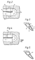
- the passage portions 15 and 17 are separated and partially defined by a longitudinally wall member 18 which is generally planar in configuration. However, the end 19 of the wall member 18 which, in the region of the bend portion, 16 is locally thickened as can be seen more clearly if reference is made to Figure 2.
- the wall member 18 interconnects the suction and pressure flanks 20 and 21 respectively of the aerofoil portion 13.
- the flanks 20 and 21 additionally assist in defining the first and second passage portions 15 and 17.
- the locally thickened end 19 of the wall member 18 is thickened so that the thickened region only protrudes into the upstream part of the second passage portion 17. This results in the upstream portion of the second passage portion 17 progressively narrowing and then opening in the direction of cooling air flow. In contrast the downstream end of the first passage portion 15 remains substantially constant in cross-sectional area.
- the wall member 18 is angled with respect to the two aerofoil portion flanks 20 and 21. This is to facilitate easy core removal during the manufacture of the blade 10 by casting.
- the thickened wall member end 19 is further thickened in the region 22 so as to define an enlarged fillet. This ensures that in the upstream region of the second passage portion 17, the angles between the thickened wall member end 19 and the suction and pressure flanks 20 and 21 are neither significantly less than 90 o .
- the thickened end 19 of the wall member 18 additionally progressively increases in thickness towards at least one of the flanks 20,21 so as to substantially eliminate any acute angle between the at least one flank and the locally thickened wall member end 19 adjacent thereto.
- the thickened configuration of the end 19 of the wall member 18 and the angular relationship between that end 19 of the wall member 18 and the flanks 20 and 21 is important in ensuring that the air pressure loss resulting from the cooling air flow in the first passage portion 15 being turned through 180 o by the bend portion 16 is as small as possible.
- the first configuration shown in Figures 4 and 5 had a wall member 23 which was not provided with a thickened portion.
- the second configuration shown in Figures 6 and 7 had the same non-thickened wall portion 23 but was additionally provided with a turning vane 24.
- the third configuration shown in Figures 8 and 9 had a wall member 25 which was thickened at its end in a manner similar to that of the present invention. However as can be seen most clearly in Figure 9, there is no modification of the thickening in the region where the wall member 25 intersects the blade flanks 26 and 27.
- pressurised air was directed through the first passage portion 15 to flow around the bend portion 16 and through the second passage portion 17.
- the static pressure of the air was monitored at various positions in both of the first and second passage portions 15 and 17.
- A represents the peformance of the arrangement in accordance with the present invention
- B represents the performance of the configuration shown in Figures 8 and 9
- C represents the performance of the configuration shown in Figures 6 and 7
- D represents the performance of the configuration shown in Figures 4 and 5.
- Arrangement Pressure Ratio at 200mm from the bend centre A 0.933 B 0.930 C 0.922 D 0.910
- the arrangement A of the present invention results in a smaller drop in cooling air pressure resulting from parasitic losses as the air passes around the bend portion 16 than is the case with the three prior art configurations. This being so, the cooling air will be at higher pressure in the second cooling passage portion 17, thereby ensuring that the cooling can be used more effectively for, for instance, film cooling of the exterior of the turbine blade 10.
Landscapes
- Engineering & Computer Science (AREA)
- Mechanical Engineering (AREA)
- General Engineering & Computer Science (AREA)
- Turbine Rotor Nozzle Sealing (AREA)
Claims (6)
- Aube de turbine (10) adaptée pour une turbine d'un moteur à turbine à gaz comprenant une partie de surface sustentatrice (13) ayant des flancs de pression et d'aspiration (20, 21), lesdits flancs (20, 21) étant interconnectés à l'intérieur de ladite pallie de surface sustentatrice (11) par un élément de paroi (18) s'étendant généralement longitudinalement pour partiellement définir des première et seconde parties de passage de fluide de refroidissement (15, 17) disposées côte-à-côte et s'étendant généralement longitudinalement, lesdites première et seconde parties de passage (15, 17) étant interconnectées en relation d'écoulement de fluide en série par une partie de passage courbée (16), ladite première partie de passage (15) étant adaptée à diriger du fluide de refroidissement vers ladite partie courbée (16) et ladite seconde partie de passage (17) étant adaptée a évacuer du fluide de refroidissement de ladite partie courbée (16), ledit élément de paroi (18) étant localement épaissi dans lit région de ladite partie courbée (16) pour fournir un rétrécissement et une ouverture en série, progressif et localisés, de l'extrémité amont de ladite seconde partie de passage (17) dans lit direction générale de l'écoulement du fluide de refroidissement, caractérisée en ce que que ladite partie d'élément de paroi localement épaissie (19) est configurée de telle sorte qu'a' ladite extrémité amont de ladite seconde partie de passage (17), ladite partie d'élément de paroi localement épaissie (19) augmente progressivement en épaisseur du côté d'au moins un desdits flancs (26,27) de façon à sensiblement éliminer tout angle vif entre ledit au moins un flanc (26,27) et lit partie d'élément de paroi épaissie (19) qui est adjacente.
- Aube de turbine selon la revendication 1, caractérisée en ce que ladite partie d'élément de paroi localement épaissi (19) augmente progressivement en épaisseur du côté dudit flanc d'aspiration (26).
- Aube de turbine selon lit revendication 1, caractérisée en ce que ledit élément de paroi (18) s'étendant longitudinalement n'est pas généralement perpendiculaire auxdits flancs de pression et d'aspiration (26, 27).
- Aube de turbine selon l'une quelconque des revendications précédentes, caractérisée en ce que ladite partie de passage courbée (16) est située adjacente à l'une des étendues longitudinales de ladite partie de surface sustentatrice (13).
- Aube de turbine selon la revendication 4, caractérisée en ce que l'étendue longitudinale de ladite partie de surface sustentatrice (13) à laquelle ladite partie de passage courbée (16) est située adjacente, est celle qui constitue l'étendue dirigée radialement vers l'intérieur de ladite partie de surface sustentatrice (13) lorsque ladite aube de turbine (10) est montée dans lit turbine d'un moteur de turbine à gaz.
- Aube de turbine selon l'une quelconque des revendications précédentes, caractérisée en ce que lesdites première et seconde parties de passage de refroidissement (15, 17) sont généralement parallèles l'une à l'autre.
Applications Claiming Priority (2)
| Application Number | Priority Date | Filing Date | Title |
|---|---|---|---|
| GB9014762 | 1990-07-03 | ||
| GB909014762A GB9014762D0 (en) | 1990-07-03 | 1990-07-03 | Cooled aerofoil vane |
Publications (3)
| Publication Number | Publication Date |
|---|---|
| EP0465004A2 EP0465004A2 (fr) | 1992-01-08 |
| EP0465004A3 EP0465004A3 (en) | 1992-12-02 |
| EP0465004B1 true EP0465004B1 (fr) | 1994-12-14 |
Family
ID=10678607
Family Applications (1)
| Application Number | Title | Priority Date | Filing Date |
|---|---|---|---|
| EP91304914A Expired - Lifetime EP0465004B1 (fr) | 1990-07-03 | 1991-05-30 | Aube de turbine refroidie |
Country Status (5)
| Country | Link |
|---|---|
| US (1) | US5073086A (fr) |
| EP (1) | EP0465004B1 (fr) |
| JP (1) | JPH04232304A (fr) |
| DE (1) | DE69105837T2 (fr) |
| GB (1) | GB9014762D0 (fr) |
Families Citing this family (31)
| Publication number | Priority date | Publication date | Assignee | Title |
|---|---|---|---|---|
| US5328331A (en) * | 1993-06-28 | 1994-07-12 | General Electric Company | Turbine airfoil with double shell outer wall |
| US5484258A (en) * | 1994-03-01 | 1996-01-16 | General Electric Company | Turbine airfoil with convectively cooled double shell outer wall |
| US5472316A (en) * | 1994-09-19 | 1995-12-05 | General Electric Company | Enhanced cooling apparatus for gas turbine engine airfoils |
| US5716192A (en) * | 1996-09-13 | 1998-02-10 | United Technologies Corporation | Cooling duct turn geometry for bowed airfoil |
| US6234753B1 (en) * | 1999-05-24 | 2001-05-22 | General Electric Company | Turbine airfoil with internal cooling |
| EP1223308B1 (fr) | 2000-12-16 | 2007-01-24 | ALSTOM Technology Ltd | Composante d'une turbomachine |
| AU2002342500A1 (en) * | 2001-12-10 | 2003-07-09 | Alstom Technology Ltd | Thermally loaded component |
| US7547190B1 (en) * | 2006-07-14 | 2009-06-16 | Florida Turbine Technologies, Inc. | Turbine airfoil serpentine flow circuit with a built-in pressure regulator |
| GB0915680D0 (en) | 2009-09-09 | 2009-10-07 | Rolls Royce Plc | Cooled aerofoil blade or vane |
| US8562286B2 (en) * | 2010-04-06 | 2013-10-22 | United Technologies Corporation | Dead ended bulbed rib geometry for a gas turbine engine |
| GB201102719D0 (en) * | 2011-02-17 | 2011-03-30 | Rolls Royce Plc | Cooled component for the turbine of a gas turbine engine |
| US8864467B1 (en) | 2012-01-26 | 2014-10-21 | Florida Turbine Technologies, Inc. | Turbine blade with serpentine flow cooling |
| JP5980137B2 (ja) * | 2013-02-04 | 2016-08-31 | 三菱重工業株式会社 | タービン用翼 |
| US9528379B2 (en) | 2013-10-23 | 2016-12-27 | General Electric Company | Turbine bucket having serpentine core |
| US9551226B2 (en) | 2013-10-23 | 2017-01-24 | General Electric Company | Turbine bucket with endwall contour and airfoil profile |
| US9670784B2 (en) | 2013-10-23 | 2017-06-06 | General Electric Company | Turbine bucket base having serpentine cooling passage with leading edge cooling |
| US9797258B2 (en) * | 2013-10-23 | 2017-10-24 | General Electric Company | Turbine bucket including cooling passage with turn |
| US9638041B2 (en) | 2013-10-23 | 2017-05-02 | General Electric Company | Turbine bucket having non-axisymmetric base contour |
| JP2018512535A (ja) * | 2015-03-17 | 2018-05-17 | シーメンス エナジー インコーポレイテッド | 非束縛的な流れ変向ガイド構造を有するタービンブレード |
| US10107108B2 (en) | 2015-04-29 | 2018-10-23 | General Electric Company | Rotor blade having a flared tip |
| DE102015112643A1 (de) * | 2015-07-31 | 2017-02-02 | Wobben Properties Gmbh | Windenergieanlagen-Rotorblatt |
| US10119406B2 (en) * | 2016-05-12 | 2018-11-06 | General Electric Company | Blade with stress-reducing bulbous projection at turn opening of coolant passages |
| US10605096B2 (en) * | 2016-05-12 | 2020-03-31 | General Electric Company | Flared central cavity aft of airfoil leading edge |
| EP3673152A1 (fr) * | 2017-08-24 | 2020-07-01 | Siemens Aktiengesellschaft | Profil aérodynamique de rotor de turbine et procédé correspondant pour la réduction de la perte de pression dans une cavité à l'intérieur d'une pale |
| US10718219B2 (en) * | 2017-12-13 | 2020-07-21 | Solar Turbines Incorporated | Turbine blade cooling system with tip diffuser |
| DE102018119572A1 (de) * | 2018-08-13 | 2020-02-13 | Man Energy Solutions Se | Kühlsystem zum aktiven Kühlen einer Turbinenschaufel |
| FR3096074B1 (fr) * | 2019-05-17 | 2021-06-11 | Safran Aircraft Engines | Aube de turbomachine à bord de fuite ayant un refroidissement amélioré |
| DE102019125779B4 (de) * | 2019-09-25 | 2024-03-21 | Man Energy Solutions Se | Schaufel einer Strömungsmaschine |
| DE102021204782A1 (de) * | 2021-05-11 | 2022-11-17 | Siemens Energy Global GmbH & Co. KG | Verbesserte Schaufelspitze im Neuteil oder repariertem Bauteil und Verfahren |
| KR20260003240A (ko) * | 2023-06-05 | 2026-01-06 | 미츠비시 파워 가부시키가이샤 | 터빈 동익 및 가스 터빈 |
| DE102024206063A1 (de) | 2024-06-28 | 2025-12-31 | Rolls-Royce Deutschland Ltd & Co Kg | Turbinenschaufel, insbesondere für ein Gasturbinentriebwerk |
Family Cites Families (6)
| Publication number | Priority date | Publication date | Assignee | Title |
|---|---|---|---|---|
| GB2041100B (en) * | 1979-02-01 | 1982-11-03 | Rolls Royce | Cooled rotor blade for gas turbine engine |
| US4416585A (en) * | 1980-01-17 | 1983-11-22 | Pratt & Whitney Aircraft Of Canada Limited | Blade cooling for gas turbine engine |
| US4515526A (en) * | 1981-12-28 | 1985-05-07 | United Technologies Corporation | Coolable airfoil for a rotary machine |
| US4583914A (en) * | 1982-06-14 | 1986-04-22 | United Technologies Corp. | Rotor blade for a rotary machine |
| GB2165315B (en) * | 1984-10-04 | 1987-12-31 | Rolls Royce | Improvements in or relating to hollow fluid cooled turbine blades |
| JPS62271902A (ja) * | 1986-01-20 | 1987-11-26 | Hitachi Ltd | ガスタ−ビン冷却翼 |
-
1990
- 1990-07-03 GB GB909014762A patent/GB9014762D0/en active Pending
-
1991
- 1991-05-30 EP EP91304914A patent/EP0465004B1/fr not_active Expired - Lifetime
- 1991-05-30 DE DE69105837T patent/DE69105837T2/de not_active Expired - Lifetime
- 1991-06-19 US US07/717,502 patent/US5073086A/en not_active Expired - Lifetime
- 1991-06-21 JP JP3150233A patent/JPH04232304A/ja not_active Withdrawn
Also Published As
| Publication number | Publication date |
|---|---|
| GB9014762D0 (en) | 1990-10-17 |
| JPH04232304A (ja) | 1992-08-20 |
| US5073086A (en) | 1991-12-17 |
| DE69105837D1 (de) | 1995-01-26 |
| DE69105837T2 (de) | 1995-04-27 |
| EP0465004A3 (en) | 1992-12-02 |
| EP0465004A2 (fr) | 1992-01-08 |
Similar Documents
| Publication | Publication Date | Title |
|---|---|---|
| EP0465004B1 (fr) | Aube de turbine refroidie | |
| EP1022432B1 (fr) | Aube de turbine à gaz refroidie | |
| EP2825748B1 (fr) | Canal de refroidissement pour un moteur à turbine à gaz et moteur à turbine à gaz | |
| EP1055800B1 (fr) | Aube de turbine avec refroidissement interne | |
| US5387085A (en) | Turbine blade composite cooling circuit | |
| EP1798379B1 (fr) | Aube statorique à refroidissement à contre-courant | |
| US5738493A (en) | Turbulator configuration for cooling passages of an airfoil in a gas turbine engine | |
| US6997679B2 (en) | Airfoil cooling holes | |
| EP1918521B1 (fr) | Aube statorique pour compresseur à angle de calage variable ayant un rayon de raccordement s'étendant au delà du pivot | |
| US5688108A (en) | High temperature rotor blade attachment | |
| US20050106027A1 (en) | Turbine rotor blade for gas turbine engine | |
| EP1630354A2 (fr) | Aube refroidie de turbine à gaz | |
| US6382908B1 (en) | Nozzle fillet backside cooling | |
| EP3514329B1 (fr) | Profile aérodynamique avec séparateur de saletés pour un trou de refroidissement par film | |
| EP3505726B1 (fr) | Ensemble d'aube pour moteur de turbine à gaz | |
| GB2189553A (en) | Cooled vane | |
| US7094032B2 (en) | Turbine blade shroud cutter tip | |
| EP2597263A1 (fr) | Ensemble des aubes pour système de turbine | |
| US10954801B2 (en) | Cooling circuit with shaped cooling pins | |
| US6004100A (en) | Trailing edge cooling apparatus for a gas turbine airfoil | |
| EP3064712B1 (fr) | Profil aérodynamique d'aube avec insert de chicane | |
| EP1908922B1 (fr) | Dispositif pour le refroidissement hybride à évaporation et par film d'une aube de turbine | |
| EP1013881B1 (fr) | Aillettes refroidissables | |
| US8162594B2 (en) | Cooled blade for a turbomachine | |
| US6520741B1 (en) | Turbomachine blade |
Legal Events
| Date | Code | Title | Description |
|---|---|---|---|
| PUAI | Public reference made under article 153(3) epc to a published international application that has entered the european phase |
Free format text: ORIGINAL CODE: 0009012 |
|
| AK | Designated contracting states |
Kind code of ref document: A2 Designated state(s): DE FR GB IT |
|
| PUAL | Search report despatched |
Free format text: ORIGINAL CODE: 0009013 |
|
| AK | Designated contracting states |
Kind code of ref document: A3 Designated state(s): DE FR GB IT |
|
| 17P | Request for examination filed |
Effective date: 19921110 |
|
| 17Q | First examination report despatched |
Effective date: 19940405 |
|
| GRAA | (expected) grant |
Free format text: ORIGINAL CODE: 0009210 |
|
| ITF | It: translation for a ep patent filed | ||
| AK | Designated contracting states |
Kind code of ref document: B1 Designated state(s): DE FR GB IT |
|
| REF | Corresponds to: |
Ref document number: 69105837 Country of ref document: DE Date of ref document: 19950126 |
|
| ET | Fr: translation filed | ||
| PLBE | No opposition filed within time limit |
Free format text: ORIGINAL CODE: 0009261 |
|
| STAA | Information on the status of an ep patent application or granted ep patent |
Free format text: STATUS: NO OPPOSITION FILED WITHIN TIME LIMIT |
|
| 26N | No opposition filed | ||
| REG | Reference to a national code |
Ref country code: GB Ref legal event code: IF02 |
|
| PG25 | Lapsed in a contracting state [announced via postgrant information from national office to epo] |
Ref country code: IT Free format text: LAPSE BECAUSE OF NON-PAYMENT OF DUE FEES Effective date: 20050530 |
|
| PGFP | Annual fee paid to national office [announced via postgrant information from national office to epo] |
Ref country code: FR Payment date: 20100611 Year of fee payment: 20 |
|
| PGFP | Annual fee paid to national office [announced via postgrant information from national office to epo] |
Ref country code: DE Payment date: 20100521 Year of fee payment: 20 |
|
| PGFP | Annual fee paid to national office [announced via postgrant information from national office to epo] |
Ref country code: GB Payment date: 20100519 Year of fee payment: 20 |
|
| REG | Reference to a national code |
Ref country code: DE Ref legal event code: R071 Ref document number: 69105837 Country of ref document: DE |
|
| REG | Reference to a national code |
Ref country code: GB Ref legal event code: PE20 Expiry date: 20110529 |
|
| PG25 | Lapsed in a contracting state [announced via postgrant information from national office to epo] |
Ref country code: GB Free format text: LAPSE BECAUSE OF EXPIRATION OF PROTECTION Effective date: 20110529 |
|
| PG25 | Lapsed in a contracting state [announced via postgrant information from national office to epo] |
Ref country code: DE Free format text: LAPSE BECAUSE OF EXPIRATION OF PROTECTION Effective date: 20110531 |