EP0465106B1 - System und Verfahren zum Laserschweissen der Innenoberfläche einer Leitung - Google Patents
System und Verfahren zum Laserschweissen der Innenoberfläche einer Leitung Download PDFInfo
- Publication number
- EP0465106B1 EP0465106B1 EP91305772A EP91305772A EP0465106B1 EP 0465106 B1 EP0465106 B1 EP 0465106B1 EP 91305772 A EP91305772 A EP 91305772A EP 91305772 A EP91305772 A EP 91305772A EP 0465106 B1 EP0465106 B1 EP 0465106B1
- Authority
- EP
- European Patent Office
- Prior art keywords
- conduit
- housing
- beam deflection
- assembly
- deflection assembly
- Prior art date
- Legal status (The legal status is an assumption and is not a legal conclusion. Google has not performed a legal analysis and makes no representation as to the accuracy of the status listed.)
- Expired - Lifetime
Links
Images


Classifications
-
- B—PERFORMING OPERATIONS; TRANSPORTING
- B23—MACHINE TOOLS; METAL-WORKING NOT OTHERWISE PROVIDED FOR
- B23K—SOLDERING OR UNSOLDERING; WELDING; CLADDING OR PLATING BY SOLDERING OR WELDING; CUTTING BY APPLYING HEAT LOCALLY, e.g. FLAME CUTTING; WORKING BY LASER BEAM
- B23K26/00—Working by laser beam, e.g. welding, cutting or boring
- B23K26/08—Devices involving relative movement between laser beam and workpiece
- B23K26/10—Devices involving relative movement between laser beam and workpiece using a fixed support, i.e. involving moving the laser beam
- B23K26/103—Devices involving relative movement between laser beam and workpiece using a fixed support, i.e. involving moving the laser beam the laser beam rotating around the fixed workpiece
- B23K26/106—Devices involving relative movement between laser beam and workpiece using a fixed support, i.e. involving moving the laser beam the laser beam rotating around the fixed workpiece inside the workpiece
-
- B—PERFORMING OPERATIONS; TRANSPORTING
- B23—MACHINE TOOLS; METAL-WORKING NOT OTHERWISE PROVIDED FOR
- B23K—SOLDERING OR UNSOLDERING; WELDING; CLADDING OR PLATING BY SOLDERING OR WELDING; CUTTING BY APPLYING HEAT LOCALLY, e.g. FLAME CUTTING; WORKING BY LASER BEAM
- B23K26/00—Working by laser beam, e.g. welding, cutting or boring
- B23K26/20—Bonding
- B23K26/21—Bonding by welding
- B23K26/24—Seam welding
- B23K26/28—Seam welding of curved planar seams
-
- F—MECHANICAL ENGINEERING; LIGHTING; HEATING; WEAPONS; BLASTING
- F22—STEAM GENERATION
- F22B—METHODS OF STEAM GENERATION; STEAM BOILERS
- F22B37/00—Component parts or details of steam boilers
- F22B37/002—Component parts or details of steam boilers specially adapted for nuclear steam generators, e.g. maintenance, repairing or inspecting equipment not otherwise provided for
- F22B37/003—Maintenance, repairing or inspecting equipment positioned in or via the headers
Definitions
- This invention generally relates to systems and methods for laser welding the inner surface of a conduit, and is specifically concerned with a system and method for laser welding a sleeve to the inner surface of a heat exchanger tube in order to repair the tube.
- Nuclear steam generators are generally comprised of a bowl-shaped primary side, a tubesheet disposed over the top of the primary side, and a cylindrically shaped secondary side which in turn is disposed over the tubesheet.
- Hot, radioactive water from the reactor core circulates through the primary side of the steam generator, while non-radioactive water is introduced into the secondary side.
- the tubesheet hydraulically isolates but thermally connects the primary side to the secondary side by means of a number of U-shaped heat exchanger tubes whose bottom ends are mounted in the tubesheet. Hot, radioactive water from the primary side flows through the interior of these heat exchanger tubes while the exterior of these tubes comes into contact with the non-radioactive water in the secondary side in order to generate non-radioactive steam.
- the legs of the U-shaped heat exchanger tubes extend through bores present in a plurality of horizontally-oriented support plates that are vertically spaced from one another, while the ends of these tubes are mounted within bores located in the tubesheet.
- Small, annular spaces are present between these heat exchanger tubes and the bores in the support plates and the tubesheet which are known in the art as "crevice regions".
- Such crevice regions provide only a very limited flow path for the feed water that circulates throughout the secondary side of the steam generator, which causes "dry boiling” to occur wherein the feed water boils so rapidly that these regions can actually dry out for brief periods of time before they are again immersed by the surrounding feed water.
- This chronic drying-out causes impurities in the water to precipitate and collect in these crevice regions. These precipitates ultimately create sludge and other debris that promote the occurrence of stress corrosion cracking in the regions of the tubes surrounded by the bores of the tubesheet and the support plates which, if not repaired, will ultimately allow radioactive water from the primary side to contaminate the non-radioactive water in the secondary side of the generator.
- a repair procedure known as "sleeving” has been developed wherein a tubular sleeve formed from the same stainless steel as the damaged heat exchanger tube is slid up within the tube so that it traverses the corroded or otherwise damaged length of the tube. The ends of the sleeve are then affixed to the inner surfaces of the tubes in order to form a hydraulic "bridge" across the corroded or otherwise degraded length of the tube.
- a laser welding system that is capable of welding sleeves into heat exchanger tubes that are less than 19.05 mm in diameter.
- a welding system would be inexpensive to construct, and easy and reliable in operation.
- this system could be easily, quickly and remotely positioned within a desired tube to be sleeved by the use of robotic positioning devices already in existence.
- the invention is both a system and method for laser welding the inner surfaces of conduits, such as the heat exchanger tubes in nuclear steam generators, that avoids or at least ameliorates the aforementioned disadvantages associated with the prior art.
- the invention is a system for laser welding the inner surface of a conduit, comprising an elongated tubular housing having a distal and a proximal end, a light conduit connected to the proximal end of said tubular housing for conducting light energy through said tubular housing, a laser source connected to said light conduit for generating light energy, a beam deflection assembly rotatably mounted on the distal end of said housing and optically connected to said light conduit for directing said light energy to the inner surface of the conduit, and a rotary drive assembly for rotating said beam deflection assembly to direct said light energy around the inner surface of the conduit, including a motion transducer for converting linear movement parallel to the longitudinal axis of the housing to rotary motion.
- the system generally comprises a rotary drive assembly for rotating a beam deflection assembly that directs laser light around the inner surface of the conduit which includes a motion transducer for converting linear movement along the longitudinal axis of the conduit to rotary motion that has a driven member disposed in a tubular housing which is connected to a beam deflection assembly, and an elongated drive member axially movable within the tubular housing.
- Both the drive member and the driven member are preferably tubular members that are concentrically disposed within said tubular housing, and one of said tubular members includes a helical groove while the other includes a follower disposed in the groove such that when the drive member is slid along the longitudinal axis of the tubular housing, the driven member rotates.
- the driven member In order to convert the rotational movement of the driven member into a smooth, fine-pitched helical motion that allows the beam deflection assembly to accurately direct a thin laser beam around the inside of the conduit being welded, the driven member includes a threaded portion along a section of its outer diameter which engages a threaded portion present on the inner diameter of the tubular housing.
- the housing of the system includes a securing assembly having an inflatable bladder that circumscribes a portion of the outer circumference of the housing which is selectively engageable to the inner surface of the conduit whenever the bladder is filled with a pressurized fluid.
- a pressurized source of shield gas selectively inflates the bladder of the securing assembly in order to both secure the housing within the conduit, and to provide a steady stream of shield gas up through the center of the housing and out through the beam deflection assembly during a welding operation for preventing unwanted corrosion from occurring in the metal forming the conduit or tube.
- An eddy current probe is further provided within the tubular housing of the system in order to guide the system operator as to the whereabouts of the housing (and hence the whereabouts of the beam deflection assembly located on the distal end of the housing) along the longitudinal axis of the conduit or tube to be welded.
- the system includes a centering assembly attached to the distal end of the beam deflection assembly for concentrically aligning the rotating beam deflection assembly with respect to the inner walls of the conduit or tube to be welded.
- the invention is also a method for welding the inner circumference of a metallic conduit by means of a laser beam deflection assembly rotatably connected to the distal end of an elongated tubular housing that contains a rotary drive assembly having a driven member connected to said beam deflection assembly, and a drive member mechanically linked to said driven member whose axial movements along the longitudinal axis of the housing cause said driven member to rotate, comprising the steps of slidably inserting the elongated tubular housing into a conduit to be welded, conducting a beam of laser light to said laser beam deflection assembly, and rotating said beam deflection assembly by remotely and axially moving said drive member relative to said housing.
- the housing of the system is slidably inserted into the conduit or tube to be welded.
- the eddy current probe is used to position the housing so that the beam deflection assembly is disposed adjacent to the section of the conduit or tube where a welding operation is desired.
- the housing is secured in this position by admitting pressurized shield gas to the inflatable bladder of the securing assembly.
- the beam deflection assembly is rotated by slidably moving the drive member contained within the housing in order to rotate the beam deflection assembly attached onto the distal end of the driven member while laser light is conducted to the beam deflection assembly.
- the drive member is slidably moved so that the driven member rotates at a rate of between 10 and 25 rpm's.
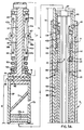
- the welding system 1 of the invention generally comprises an elongated, tubular welder housing 3 having a beam deflection assembly 5 rotationally connected to its distal end.
- a centering assembly 7 is connected to the distal end of the beam deflection assembly 5 for maintaining the latter in concentric alignment within the sleeve or tube being welded.
- a securing assembly 8 is provided near the proximal end of the welder housing 3 for selectively securing the housing 3 at a desired position along the longitudinal axis of the sleeve or tube being welded.
- a length of flexible tubing 9 is connected onto the proximal end of the welder housing 3 for housing a light conduit 10 formed from a bundle of optical fibers 141 (see Fig. 4) one of which is ultimately connected to a laser light source 11, the balance of which are used to transmit the reflection of laser light from the focusing lenses in the beam deflection assembly 5 to a temperature monitoring device included within the laser unit 11.
- the flexible tubing 9 serves the additional function of conveying shield gas up through the hollow interior of the welder housing 3 in order to apply a corrosion-impeding, inert gas onto the region of the sleeve or tube being welded by the system 1.
- a welder delivery device 14 is used to insert and withdraw the welder housing 3 from the open end of a selected heat exchanger tube.
- this delivery device 14 may be the ROSA robotic arm developed and manufactured by the Westinghouse Electric Corporation located in Pittsburgh, Pennsylvania, USA.
- a pusher-puller assembly 15 is used to extend and retract the flexible tubing 9 as the welder housing 3 is inserted and withdrawn from a selected heat exchanger tube.
- the pusher-puller assembly 15 may be constructed like the insertion and pusher drive mechanism illustrated in Figures 4A and 4B of U.S. Patent 4,757,258, issued July 12, 1988 to R. G. Kelley, Jr. et al. and assigned to the Westinghouse Electric Corporation, the entire specification of which is expressly incorporated herein by reference.
- the system 1 includes a source 17 of compressed shield gas, which may be nitrogen. As is indicated in Figure 1, the shield gas source 17 is connected to the flexible tubing 9 through the drive actuator assembly 12.
- the welding system 1 of the invention is particularly useful in welding tubular sleeves 19 to the interior surfaces 20 of the heat exchanger tubes 22 in a nuclear steam generator 23.
- Such generators 23 generally comprise a tubesheet 24 that hydraulically isolates the lower, bowl-shaped primary side 26 of the generator 23 from the upper, cylindrically shaped secondary side 28 of the generator 23.
- the tubesheet 24 includes a plurality of bores through which the lower ends of the heat exchanger tubes 22 extend.
- the lower ends of each of the tubes 22 are open, and are secured to the bores of the tubesheet 24 by means of an annular weld (not shown).
- an annular weld not shown.
- each of the heat exchanger tubes 22 are further laterally supported throughout the length of the secondary side 28 of the steam generator 23 by a series of support plates 29.
- Each of these support plates 29 includes a plurality of bores 30 through which the heat exchanger tubes 22 extend.
- an annular clearance exists between the bores 30 and the support plates 29, and the exterior surface of the heat exchanger tubes 22.
- sludge and other debris accumulate in these annular spaces due to a combination of poor circulation of the ambient water through the space and localized boiling. This sludge and other debris can promote the occurrence of stress corrosion cracking in the section of the heat exchanger tubes 22 surrounded by the bores 30 and the support plates 29.
- the heat exchanger tubes 22 are allowed to crack in these regions before the installation of reinforcing sleeves 19, hot, radioactive water from the primary side 26 of the generator 23 can flow through the walls of the tubes 22 and contaminant the non-radioactive water that surrounds these tubes 22 in the secondary side 28 of the generator 23.
- the purpose of the welding system 1 of the invention is to secure such sleeves 19 in place against the interior surface 20 of the heat exchanger tube 22 as quickly and as reliably as possible.
- the welding system 1 is capable of remotely performing such welding operations through the manways 32 located in the primary side 26 of the generator 23.
- the centering assembly 7 of the system 1 is generally formed from a support shaft 37, and three roller linkages 38 disposed around the shaft 37 approximately 120° from one another.
- Each of the roller linkages 38 includes a centering roller 40 in its midsection which is flanked by a pair of link members 42a,b.
- Connecting pins 44a,b,c connect the link members 42a,b to a sliding ring 46, the centering roller 40, and a guide sleeve 47, respectively.
- a compression spring 50 biases the sliding ring 46 upwardly towards the fixed ring 45.
- the compression spring 50 is captured between the sliding ring 46, and an annular shoulder 51 that circumscribes the lower portion of support shaft 37.
- centering assembly 7 is similar in structure and operation to the roller assemblies disclosed in U.S. Patent 4,736,092 invented by William E. Pirl and assigned to the Westinghouse Electric Corporation, the entire specification of which is expressly incorporated herein by reference.
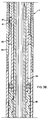
- the beam deflection assembly 5 is formed from a tubular housing 57 having a distal portion which extends above the elongated, tubular welding housing 3 and a proximal portion which is concentrically disposed within the welder housing 3.
- the distal end 59 of the tubular housing 57 includes a connector pin 61 which extends through a bore 62 located in the proximal end of the support shaft 37 of the centering assembly 7 to rigidly secure the centering assembly 7 over the top end of beam deflection assembly 5.
- the proximal end 63 of the tubular housing 57 includes recesses for housing at least four ball bearings 65 which rollingly engage against the inner walls of the distal end of the welder housing 3.
- An optical coupling 67 is disposed within the tubular housing 57 near the proximal end 63 thereof which in turn is connected to the distal end of the light conduit 10.
- the optical coupling 67 directs the laser light flowing through the conduit 10 onto a pair of focusing lenses 69a,b, which concentrate this light into a narrow beam which strikes the 45° mirror 71.
- the mirror 71 in turn deflects this narrow beam of laser light out through a beam port 73 located in the side of the tubular housing 57.
- the tubular housing 57 rotates with respect to the welder housing 3 so that the beam of laser light emanating through the port 73 can circumscribe the inner wall of a sleeve 19.
- a rotary drive assembly 75 operates to rotate the beam deflection assembly 5 with respect to the welder housing 3.
- the drive assembly 75 includes a driven tube 77 whose distal end is integrally connected with the proximal end of the tubular housing 57 of the beam deflection assembly 5 and whose proximal end 81 includes a threaded fitting 83 which engages a threaded coupling 85 which forms part of the welder housing 3.
- Located just above the threaded fitting 83 is a follower ball 87 which is rotatably supported within a bore located in the walls of the driven tube 77.
- Concentrically disposed within the driven tube 77 is a drive tube 89.
- the drive tube 89 has a distal end 90 that is located just below a coupler sleeve 91 whose function will become apparent hereinafter.
- An anti-rotation pin 92 is mounted just below the distal end 90 of the drive tube 89. This pin is slidably received within a slot 109 in an inner support tube 99 which, like the drive tube 89, does not rotate with respect to the tubular welder housing 3 when the rotary drive assembly 75 rotates the beam deflection assembly 5 during the operation of the system 1.
- a spiral groove 93 circumscribes the outer surface of the drive tube 89 between its distal end 90 and its proximal end 94.
- this spiral groove 93 circumscribes the diameter of the drive tube 89 approximately five times.
- a piston sleeve 95 whose function is to smoothly dampen the motion of the drive tube with respect to the surrounding welder housing 3 when the drive tube 89 is slidably withdrawn along the longitudinal axis of the housing 3.
- a push-pull cable 97 is further connected to the proximal end of the drive tube 89 through the piston sleeve 95 for the purpose of pulling the tube 89 downwardly through the interior of the welder housing 3 (see Fig. 5).
- the distal end 101 of the support tube 99 includes a slot 103 for slidably receiving a retainer pin 105 mounted through the inner wall of the coupler sleeve 91.
- a much longer slot 109 is provided along the longitudinal axis of the inner support tube 99 below the slot 103. As has been indicated earlier, this longer, second slot 109 slidably receives the anti-rotation pin 92 that is connected to the inner wall of the drive tube 89.
- the proximal end 111 of the inner support tube 99 is rigidly attached to the distal end 112 of the eddy current probe body 113, which in turn is rigidly connected to the bottom end of the tubular welder housing 3.
- the operation of the rotary drive assembly 75 may be best understood with respect to Figure 3E.
- the drive tube 89 is slidably moved downwardly with respect to both the driven tube 77 and the tubular welder housing 3. Because of the engagement between the anti-rotation pin 92 affixed to the inner wall of the drive tube 89 and the slot 109 present along the outer wall of the inner support tube 99, the drive tube 89 cannot rotate as it is pulled longitudinally downwardly with respect to the driven tube 77.
- piston sleeve 95 helps to dampen the linear movement of the drive tube 89 down the longitudinal axis of the welder housing 3, which in turn creates a smooth helical movement of the beam deflection assembly 5 with respect to the welder housing 3.
- the piston sleeve 95 also includes seals to force the shield gas to travel through the center of the housing 3 and out of port 95, instead of out of the sides of the housing 3.
- the eddy current probe 13 is provided with the previously mentioned probe body 113 which is preferably formed from a non-metallic material, such as Delrin R or nylon.
- the distal end 112 of the probe body 113 is screwed into the proximal end 114 of the tubular welder housing 3, as well as the proximal end 111 of the inner support tube 99, whereas the proximal end 115 of the probe body 113 is screwed into a coupling 117 which forms the upper portion of the securing assembly 8.
- the middle portion of the probe body 113 is circumscribed by a probe coil 118 whose leads are connected to a multi-frequency current generator which, in the preferred embodiment, is a MIZ 18 current generator manufactured by Zetec located in Isaquah, Washington, USA.
- a multi-frequency current generator which, in the preferred embodiment, is a MIZ 18 current generator manufactured by Zetec located in Isaquah, Washington, USA.
- the eddy current probe 13 is used to precisely locate the top and bottom edges of the support plate 29 near the center of the sleeving operation in accordance with the method set forth in U.S. Patent No. 4,814,702 invented by John M. Driggers, and assigned to the Westinghouse Electric Corporation, the entire specification which is expressly incorporated herein by reference.
- the top and bottom edges of the plate 29 are used as reference points in positioning the beam deflection assembly 5 at the end of a sleeve 19.
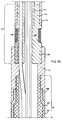
- the securing assembly 8 includes an expandable bladder 122 formed from a sleeve of a resilient plastic material such as polyurethane which circumscribes a cylindrical mandrel 124.
- the distal end of the bladder 122 is captured between the mandrel 124, and the proximal end of the previously mentioned coupling 117, while the distal end is captured between the proximal end of the mandrel 124, and another coupling 130.
- This mandrel 124 includes a hollow interior for conducting both the light conduit 10 and the push-pull cable 97, as well as a radially-oriented gas port 131.
- the proximal end 132 of the coupling 130 is circumscribed by a plurality of ridges which help to secure the distal end 133 of the flexible tubing 9 when this tubing is pushed over the coupling and 132 in the position shown in Figure 3C.
- the ridges on the coupling end 132 further help to make this connection gas-tight between the tubing 9, and the coupling 130.
- the flexible tubing 9 includes a plurality of bearing assemblies 134 for minimizing frictional engagement between the light conduit 10 and the push-pull cable 97 and the inner walls of the tubing 9.
- Each of the bearing assemblies 134 in turn includes a bearing housing 136 which houses at least three ball bearings 138 that rollingly engage the inner surface of the tubing 9.
- the bearing housing 136 further includes a crescent-shaped recess through which the push-pull cable 97 extends.
- the bearings 138 on the periphery on the bearing housing 136 not only help to eliminate friction between the bearing housing 136 and the inner wall of the flexible tubing 9, but further prevent the push-pull cable 97 from coming into frictional engagement with the bearing housing 136.
- Gas passages 139 having a roughly triangular shape are defined between the bearings 138 on the periphery of the bearing housing 136, and the body of the push-pull cable 97. These gas passageways 139 allow shield gas to travel easily through each of the bearing assemblies 134 disposed along the longitudinal axis of the flexible tubing 9. Coaxial cables 140a,b extend through the gas passageways 139 in order to bring electrical current to the coil 118 of the eddy current probe 113. Additionally, triangular openings are provided through the bearing housing 136 in order to conduct the optical fibers 141 and the steel reinforcing fiber 142 which together form the light conduit 10.
- the bearing assemblies 134 remain fairly stationary within the flexible tubing 9, while the optical fibers 141 and steel fiber 142 which form the light conduit 10, and the coaxial cables 140a,b move only a short distance along the axis of the tubing 9 since they must follow the linear component of the helical movement of the beam deflection assembly 5.
- the push-pull cable 97 moves a longer distance along the longitudinal axis of the flexible tubing 9 and the tubular welder housing 3 to operate the rotary drive assembly 75.
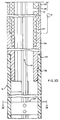
- the drive actuator assembly 12 of the system 1 is provided with a retainer bracket 147 onto which a linear actuator 149 is mounted.
- the linear actuator 149 includes a pneumatic cylinder 150 that is secured onto a rear support flange 151 on the retainer bracket 147.
- a piston rod 152 is reciprocably movable within the pneumatic cylinder 150, and terminates in an actuator bracket 153 which in turn is connected to a coupling flange 154 that defines the proximal end of the push-pull cable 97.
- the push-pull cable 97 is moved linearly along the longitudinal axis of the tubing 9 as the piston rod 152 reciprocates within the pneumatic cylinder 150.
- the light conduit 10 slidably extends through a bore 155 located in the actuator bracket 153 since it does not move the same distance linearly as the reciprocating actuator bracket 153.
- a gas conduit 156 that is connected to the source of compressed shield gas 17 is in turn connected onto a nipple 157 that extends out from a shield gas chamber 158 located on the distal end of the retainer bracket 147 as shown.
- This shield gas chamber 158 is provided with an outlet nipple 159 on its front wall 161 for conducting both the light conduit 10, the push-pull cable 97, and shield gas flowing into the chamber 158 via the inlet nipple 157 up through the flexible tubing 9.
- a tube coupler 162 connects the outlet nipple 159 to the flexible tubing 9.
- the rear wall 163 of the shield gas chamber 158 is provided with a bore 164 for again conducting both the light conduit 10, and the push-pull cable 97.
- a gasket 165 circumscribes the bore 164 to minimize gas losses out of the shield gas chamber 158 as the push-pull cable 97 is reciprocated through this chamber 158. Additionally, the rear support flange 151 located near the middle of the retainer bracket 147 includes a bore 167 for conducting the light conduit 10 to the outlet of the laser unit 11.
- the manway 32 of the steam generator 23 is opened, and the welder delivery device 14 is installed on the underside of the tubesheet 24 of the generator 23 is shown, while the pusher-puller assembly 15 is installed on a support bracket just outside of the manway 32.
- the system operator feeds the tubular welder housing 3 through the pusher-puller assembly 15 where it can be grasped by the welder delivery device 14, which is capable of remotely inserting the tubular welder housing 3 into the open end of a selected heat exchanger tube 22.
- the welder housing 3 is inserted into the open end of a tube 22 into which a sleeve 19 has already been delivered.
- the beam deflection assembly 5 is properly positioned with respect to one of the ends of the sleeve 19 by moving the tubular welder housing 3 up and down within the heat exchanger tube 22 while using the eddy current probe 13 to detect the presence of the support plate 29 which the sleeve 19 traverses. Since the system operator knows the precise distance between the beam port 73 of the beam deflection assembly 5 and the coil 118 of the eddy current probe 13, it is a simple matter for the system operator to lower the beam deflection assembly 5 into a proper position with respect to one of the ends of the sleeve 19 once the eddy current coil 118 detects the edges of the support plate 29 that the sleeve 19 traverses. Alternatively, the eddy current coil 118 may be used directly to detect the ends of the sleeve 19.
- the system operator opens a valve (not shown) which allows pressurized shield gas from source 17 to enter the shield gas chamber 158 of the drive actuator assembly 12. This gas flows up through the flexible tubing 9, and expands the bladder 122 of the securing assembly 8 into engagement against the inner surface 20 of the heat exchanger tube 22.
- the system operator simultaneously actuates the laser unit 11 and the linear actuator 149 of the drive actuator assembly 12.
- the linear actuator 149 rotates the beam deflection assembly 5 at a rate of approximately 10 to 20 rpm's.
- the tubular welder housing 3 is repositioned by cutting off the supply of pressurized shield gas to the shield gas chamber 158 in order to relax the bladder 122 of the securing assembly 8, and by using the welder delivery device 14 and the eddy current probe 13 to place the beam deflection assembly 5 adjacent to the unwelded end of the sleeve 19. The method is then repeated so that both ends of the sleeve 19 are welded to the interior surface 20 of the tube 22.
Landscapes
- Physics & Mathematics (AREA)
- Optics & Photonics (AREA)
- Engineering & Computer Science (AREA)
- Mechanical Engineering (AREA)
- Plasma & Fusion (AREA)
- High Energy & Nuclear Physics (AREA)
- Thermal Sciences (AREA)
- General Engineering & Computer Science (AREA)
- Laser Beam Processing (AREA)
Claims (21)
- System (1) zum Laserschweissen der Innenoberfläche (20) einer Leitung (22), das folgendes umfasst:
ein langgestrecktes rohrförmiges Gehäuse (57) mit einem distalen (59) und einem proximalen Ende (63);
eine Lichtleitung (10), die an das proximale Ende (63) des rohrförmigen Gehäuses (57) angeschlossen ist, um Lichtenergie durch das rohrförmige Gehäuse (57) zu leiten;
eine Laserquelle (11), die an die Lichtleitung (10) angeschlossen ist, um Lichtenergie zu erzeugen;
eine Strahlablenkungsanordnung (5), die drehbar auf dem distalen Ende des Gehäuses (57) angeordnet ist, und optisch an die Lichtleitung (10) angeschlossen ist, um die Lichtenergie auf die innere Oberfläche (20) des Leitung (22) zu richten, und eine drehbare Antriebsanordnung (75), um die Strahlablenkungsanordnung zu drehen, um die Lichtenergie um die innere Oberfläche (20) der Leitung zu richten, gekennzeichnet durch Einschliessen eines Bewegungswandlers (77, 89), um Linearbewegung parallel zur Längsachse des Gehäuses (57) in Drehhewegung umzuwandeln. - Wie in Anspruch 1 definiertes System (1), in dem der Bewegungswandler (77, 89) der drehbaren Antriebsanordnung (75) ein angetriebenes Glied (77) einschliesst, das in dem Gehäuse (57) angeordnet ist und an die Strahlablenkungsanordnung (5) angeschlossen ist, und ein langgestrecktes Antriebsglied, das in dem Gehäuse (57) axial bewegt werden kann.
- Wie in Anspruch 2 definiertes System (1), in dem eines der Glieder (89) eine Schraubennut einschliesst, und das andere Glied (77) ein Nachfolgeglied (87) einschliesst, das in der Nut (93) angeordnet ist.
- Wie in Anspruch 3 definiertes System (1), in dem das angetriebene Glied (77) und das Antriebsglied (89) Rohre (77, 89) sind, die konzentrisch in dem Gehäuse (57) angeordnet sind.
- Wie in Anspruch 3 definiertes System (1), in dem der Bewegungswandler (77, 89) weiterhin ein Antidrehglied (92) einschliesst, um zu verhindern, dass sich das Antriebsglied (89) relativ zum Gehäuse (57) dreht.
- Wie in Anspruch 2 definiertes System (1), in dem der Bewegungswandler (77, 89) weiterhin ein Kabel (97) einschliesst, das an dem Antriebsglied (89) angeschlossen ist, um das Antriebsglied (89) axial in dem Gehäuse (57) zu bewegen.
- Wie in Anspruch 2 definiertes System (1), in dem das angetriebene Glied (77) an dem Gehäuse (57) mit Hilfe einer Windung befestigt ist, so dass die von dem Antriebsglied (89) auf das angetriebene Glied abgegebene Drehbewegung eine schraubenförmige Drehbewegung ist, die verursacht, dass die Lichtenergie, die aus Strahlablenkungsanordnung (5) gerichtet wird, sich axial entlang der inneren Oberfläche (20) der Leitung (22), als auch um den Umfang der inneren Oberfläche (20) bewegt.
- Wie in Anspruch 1 definiertes System, weiterhin gekennzeichnet durch eine Befestigungsanordnung (8), um das langgestreckte rohrförmige Gehäuse (57) abnehmbar in dem Leitung (22) zu befestigen.
- Wie in Anspruch 8 definiertes System (1), in dem die Befestigungsanordnung (8) eine aufblasbare Blase (122) einschliesst, die einen Teil des äusseren Umfangs des Gehäuses (57) umschreibt, das an der inneren Oberfläche (20) der Leitung (22) befestigt werden kann.
- Wie in Anspruch 1 definiertes System, das weiterhin durch eine Sonde (13) gekennzeichnet ist, die an das Gehäuse (57) angeschlossen ist, um die Gegenwart eines Metallkörpers (24, 29) um die Leitung (22), die geschweisst werden soll, aufzufinden.
- Wie in Anspruch 5 definiertes System (1) zum Laserschweissen, in dem die Lichtleitung (10) ein faseroptisches Kabel (141) einschliesst, das im Inneren des angetriebenen Gliedes (77) und des Antriebsgliedes (89) angeordnet ist.
- Wie in Anspruch 1 definiertes System (1) zum Laserschweissen, in dem die Strahlablenkungsanordnung (5) eine Fokussierungslinse (64a,b) einschliesst, um Licht, das aus dem distalen Ende der Lichtleitung (10) übertragen wird, zu fokussieren, und einen Spiegel (71), um das fokussierte Licht auf die innere Oberfläche (20) der Leitung (22) zu reflektieren.
- Wie in Anspruch 9 definiertes System (1) zum Laserschweissen, weiterhin durch eine Quelle (17) aus unter Druck gesetztem Schutzgas definiert, und in dem das Gehäuse (57) einen Durchgangsweg (139) einschliesst, um das Schutzgas von seinem proximalen Ende (63) zu einem Schweissaktivitätsgebiet zu leiten, das in der Nähe seines distalen Endes (59) angeordnet ist.
- Wie in Anspruch 13 definiertes System (1) zum Laserschweissen, in dem die Blase (122) der Befestigungsanordnung (8) mit der Quelle (17) von unter Druck gesetztem Schutzgas in Verbindung steht, so dass das Gas die Blase (122) wahlweise in eine Greifbefestigung mit der inneren Oberfläche (20) der Leitung (22) expandiert.
- Wie in Anspruch 1 definiertes System (1) zum Laserschweissen, weiterhin gekennzeichnet durch eine Zentrieranordnung (7), um die Strahlablenkungsanordnung (5) entlang der Drehachse der Leitung (22) zu zentrieren.
- Verfahren zum Schweissen der inneren Oberfläche einer metallischen Leitung (20) mittels einer Laserstrahlablenkungsanordnung (5), die drehbar am distalen Ende (59) eines langgestreckten rohrförmigen Gehäuses (57) angeschlossen ist, das eine Drehantriebsanordnung (5) mit einem angetriebenen Glied (77) einschliesst, das an die Strahlablenkungsanordnung (5) angeschlossen ist, und ein Antriebsglied (89), das mechanisch mit dem angetriebenen Glied (77) verbunden ist, dessen Axialbewegungen entlang der Längsachse des Gehäuses verursachen, dass sich das angetriebene Glied (77) dreht, wobei das Verfahren die folgenden Schritte umfasst:
das langgestreckte rohrförmige Gehäuse (57) wird gleitbar in eine Leitung (22) geschoben, die geschweisst werden soll;
ein Laserlichtstrahl wird zu der Laserstrahlablenkungsanordnung (5) geleitet, und die Strahlablenkungsanordnung (5) wird gedreht, indem das Antriebsglied (77) aus der Entfernung und axial relativ zu dem Gehäuse (57) bewegt wird. - Wie in Anspruch 16 definiertes Schweissverfahren, in dem die Strahlablenkungsanordnung (5) mit einer Geschwindigkeit von zwischen 20 und 30 Drehungen pro Minute gedreht wird.
- Wie in Anspruch 16 definiertes Schweissverfahren, in dem die Strahlablenkungsanordnung (5) axial entlang der inneren Oberfläche (20) der Leitung (22) zur gleichen Zeit, während sie gedreht wird, bewegt wird.
- Wie in Anspruch 16 definiertes Schweissverfahren, weiterhin gekennzeichnet durch den Schritt des Zentrierens der Strahlablenkungsanordnung (5) bezüglich der Drehachse der Leitung (22), vor dem Schritt des Leitens von Laserlicht zur Strahlablenkungsanordnung (5).
- Wie in Anspruch 16 definiertes Schweissverfahren, weiterhin gekennzeichnet durch den Schritt, das langgestreckte rohrförmige Gehäuse (57) in der Leitung (22) zu befestigen, so dass die Strahlablenkungsanordnung (5) neben einem Innenoberflächengebiet (20) der Leitung (22), die geschweisst werden soll, liegt.
- Wie in Anspruch 16 definiertes Schweissverfahren, weiterhin gekennzeichnet durch den Schritt, einen Schutzgasstrom durch das Gehäuse (57) und auf das Gebiet der Leitung, die geschweisst werden soll, zu leiten.
Applications Claiming Priority (2)
| Application Number | Priority Date | Filing Date | Title |
|---|---|---|---|
| US07/543,983 US5066846A (en) | 1990-06-26 | 1990-06-26 | System and method for laser welding the inner surface of heat exchanger tubes |
| US543983 | 1990-06-26 |
Publications (3)
| Publication Number | Publication Date |
|---|---|
| EP0465106A2 EP0465106A2 (de) | 1992-01-08 |
| EP0465106A3 EP0465106A3 (en) | 1992-04-22 |
| EP0465106B1 true EP0465106B1 (de) | 1994-08-31 |
Family
ID=24170325
Family Applications (1)
| Application Number | Title | Priority Date | Filing Date |
|---|---|---|---|
| EP91305772A Expired - Lifetime EP0465106B1 (de) | 1990-06-26 | 1991-06-26 | System und Verfahren zum Laserschweissen der Innenoberfläche einer Leitung |
Country Status (4)
| Country | Link |
|---|---|
| US (1) | US5066846A (de) |
| EP (1) | EP0465106B1 (de) |
| JP (1) | JPH04238682A (de) |
| ES (1) | ES2059062T3 (de) |
Families Citing this family (30)
| Publication number | Priority date | Publication date | Assignee | Title |
|---|---|---|---|---|
| EP0444271A3 (en) * | 1990-02-24 | 1992-03-11 | Westfalia Separator Ag | Disc for a centrifugal separator |
| US5196671A (en) * | 1990-08-17 | 1993-03-23 | Siemens Aktiengesellschaft | Device and process for the laser welding of a tube |
| FR2671503B1 (fr) * | 1991-01-11 | 1993-07-30 | Framatome Sa | Procede et tete de travail au laser. |
| US5977513A (en) | 1993-02-17 | 1999-11-02 | Electric Power Research Institute, Inc. | Apparatus and method for centering a laser welding probe within a tube using gas pressure |
| US5430270A (en) * | 1993-02-17 | 1995-07-04 | Electric Power Research Institute, Inc. | Method and apparatus for repairing damaged tubes |
| US5514849A (en) * | 1993-02-17 | 1996-05-07 | Electric Power Research Institute, Inc. | Rotating apparatus for repairing damaged tubes |
| US5491317A (en) * | 1993-09-13 | 1996-02-13 | Westinghouse Electric Corporation | System and method for laser welding an inner surface of a tubular member |
| US5371767A (en) * | 1994-02-01 | 1994-12-06 | Westinghouse Electric Corporation | System and method for laser welding an inner surface of a small diameter tubular member |
| US5667706A (en) * | 1996-05-03 | 1997-09-16 | Westinghouse Electric Corporation | Apparatus and method for laser welding the inner surface of a tube |
| DE29712264U1 (de) * | 1997-07-11 | 1998-11-12 | Sator Alexander Paul | Vorrichtung zum Verschweißen der Enden von rohrförmigen Behältern, insbesondere von Tuben |
| US6247231B1 (en) | 1997-08-27 | 2001-06-19 | Electric Power Research Institute | Method for repairing heat exchanger tubing through partial tube replacement |
| RU2135338C1 (ru) * | 1998-05-15 | 1999-08-27 | Товарищество с ограниченной ответственностью научно-производственная фирма "МГМ" | Устройство для лазерной обработки материалов |
| US6205160B1 (en) | 1998-09-24 | 2001-03-20 | Branson Ultrasonics Corporation | Laser diode array |
| US6486432B1 (en) | 1999-11-23 | 2002-11-26 | Spirex | Method and laser cladding of plasticating barrels |
| US6369352B1 (en) * | 2000-05-25 | 2002-04-09 | Unova Ip Corp. | Laser welding apparatus |
| US7378624B2 (en) * | 2005-02-11 | 2008-05-27 | Denso International America, Inc. | Method of welding a component inside a hollow vessel |
| FR2886562B1 (fr) * | 2005-06-02 | 2008-12-19 | Serimer Dasa Soc Par Actions S | Procede de soudage, en particulier de pieces tubulaires telles que des conduits metalliques mis bout a bout pour former des canalisations metalliques du type pipeline |
| US20070056939A1 (en) * | 2005-09-09 | 2007-03-15 | Colby Paul T | Method for laser cladding of tubes |
| JP5570995B2 (ja) * | 2008-10-03 | 2014-08-13 | 株式会社東芝 | 原子炉炉底部の補修方法 |
| ITUD20080238A1 (it) * | 2008-11-12 | 2010-05-12 | Proel S R L | Dispositivo di taglio/marcatura laser, particolarmente per applicazione su macchina da ricamo |
| US9168613B2 (en) | 2010-10-22 | 2015-10-27 | Paul T. Colby | Vertical laser cladding system |
| JP5814652B2 (ja) * | 2011-06-22 | 2015-11-17 | 株式会社東芝 | レーザ照射装置及びレーザ照射方法 |
| FR3030863B1 (fr) * | 2014-12-19 | 2019-06-14 | Endel Sra | Procede et dispositif d’inspection d'un generateur de vapeur |
| CN105039973B (zh) * | 2015-09-06 | 2017-11-28 | 浙江久恒光电科技有限公司 | 泵体用环状部件内表面硬密封层的成型方法 |
| WO2019209786A1 (en) * | 2018-04-23 | 2019-10-31 | Lsp Technologies, Inc. | Apparatus for laser peening hidden surfaces |
| RU2710090C1 (ru) * | 2018-10-31 | 2019-12-24 | Публичное акционерное общество "Челябинский трубопрокатный завод" (ПАО "ЧТПЗ") | Способ лазерно-дуговой сварки |
| US11445664B2 (en) | 2019-05-10 | 2022-09-20 | Deere & Company | Auger assembly for harvesting machine |
| FR3102687B1 (fr) * | 2019-10-31 | 2021-10-15 | Safran Aircraft Engines | Procede de compactage d’une peinture anti-corrosion d’une piece de turbomachine |
| CN111761260B (zh) * | 2020-06-10 | 2022-02-11 | 湖南顶立科技有限公司 | 一种用于球状壳体的加热装置 |
| KR102388903B1 (ko) * | 2022-03-02 | 2022-04-21 | 주식회사 와이케이테크 | 이종 재질의 파이프 접합방법 |
Family Cites Families (11)
| Publication number | Priority date | Publication date | Assignee | Title |
|---|---|---|---|---|
| US4525616A (en) * | 1984-01-03 | 1985-06-25 | Evans Pipeline Equipment Company | Internal pipe welding apparatus |
| US4571475A (en) * | 1984-04-27 | 1986-02-18 | Foster Wheeler Energy Corporation | Internal bore welding torch having removable flexible wand for remote welding |
| US4814702A (en) * | 1984-05-31 | 1989-03-21 | Westinghouse Electric Corp. | Process for accurately determining the position of the edges of support plates in steam generators |
| US4736092A (en) * | 1985-04-04 | 1988-04-05 | Westinghouse Electric Corp. | Braze heater assembly and method |
| US4757258A (en) * | 1985-11-27 | 1988-07-12 | Westinghouse Electric Corp. | Probe carrier system for inspecting boiler tubes |
| FR2600275B1 (fr) * | 1986-06-23 | 1988-10-21 | Framatome Sa | Machine de soudage a l'arc sous gaz inerte a electrode rotative |
| US4827098A (en) * | 1987-07-06 | 1989-05-02 | Westinghouse Electric Corp. | Flexible laser welding head for sleeve-to-tube welding |
| FR2617746A1 (fr) * | 1987-07-10 | 1989-01-13 | Framatome Sa | Dispositif de soudage a l'interieur d'un tube de petit diametre |
| EP0300458B1 (de) * | 1987-07-21 | 1991-12-18 | Mitsubishi Jukogyo Kabushiki Kaisha | Laserstrahlschweissverfahren für eine Innenumfangsfläche eines Rohres |
| US4841115A (en) * | 1988-02-25 | 1989-06-20 | St International | Orbital weldhead |
| FR2637829A1 (fr) * | 1988-10-14 | 1990-04-20 | Framatome Sa | Procede de dispositif de soudage a distance d'un manchon dans un tube notamment dans un generateur de vapeur de centrale nucleaire |
-
1990
- 1990-06-26 US US07/543,983 patent/US5066846A/en not_active Expired - Lifetime
-
1991
- 1991-06-25 JP JP3180123A patent/JPH04238682A/ja active Pending
- 1991-06-26 EP EP91305772A patent/EP0465106B1/de not_active Expired - Lifetime
- 1991-06-26 ES ES91305772T patent/ES2059062T3/es not_active Expired - Lifetime
Also Published As
| Publication number | Publication date |
|---|---|
| US5066846A (en) | 1991-11-19 |
| EP0465106A3 (en) | 1992-04-22 |
| EP0465106A2 (de) | 1992-01-08 |
| JPH04238682A (ja) | 1992-08-26 |
| ES2059062T3 (es) | 1994-11-01 |
Similar Documents
| Publication | Publication Date | Title |
|---|---|---|
| EP0465106B1 (de) | System und Verfahren zum Laserschweissen der Innenoberfläche einer Leitung | |
| US5430270A (en) | Method and apparatus for repairing damaged tubes | |
| US5182429A (en) | System and method for laser welding the inner surface of a tube | |
| US5611948A (en) | Apparatus and method for remotely positioning a probe in a tubular member | |
| EP0665080B1 (de) | Anordnung und Verfahren zum Laserschweissen an der Innenwandung von Rohren kleinen Durchmessers | |
| US4978834A (en) | Method and apparatus for remotely welding a bush inside a tube, in particular in a steam generator in a nuclear power station | |
| US5491317A (en) | System and method for laser welding an inner surface of a tubular member | |
| US5028381A (en) | Device for the ultrasonic non-destructive testing of a circular weld inside a steam generator tube | |
| US5977513A (en) | Apparatus and method for centering a laser welding probe within a tube using gas pressure | |
| US5479699A (en) | Apparatus for expanding tubular members | |
| US5006268A (en) | Device for laser welding inside a tubular element | |
| JPH0395494A (ja) | 管状要素内で作業を行う装置 | |
| JPS63259304A (ja) | 補強スリーブ及びマンドレルを同時に管へ装入する方法及び装置 | |
| US5483033A (en) | Apparatus and method for sequentially registering tool modules for a welding operation of a tube | |
| EP0626232A1 (de) | Vorrichtung und Verfahren zum Einbringen einer Hülse in die innere Oberfläche eines Rohres | |
| WO1999021678A1 (en) | Apparatus and method for electric discharge machining excavation and laser welding repair | |
| US5015828A (en) | System and method for stress-relief of welds in heat exchanger tubes | |
| CA2204017A1 (en) | Apparatus and method for remotely positioning a probe in a tubular member |
Legal Events
| Date | Code | Title | Description |
|---|---|---|---|
| PUAI | Public reference made under article 153(3) epc to a published international application that has entered the european phase |
Free format text: ORIGINAL CODE: 0009012 |
|
| AK | Designated contracting states |
Kind code of ref document: A2 Designated state(s): BE CH ES FR GB IT LI SE |
|
| PUAL | Search report despatched |
Free format text: ORIGINAL CODE: 0009013 |
|
| AK | Designated contracting states |
Kind code of ref document: A3 Designated state(s): BE CH ES FR GB IT LI SE |
|
| 17P | Request for examination filed |
Effective date: 19920707 |
|
| 17Q | First examination report despatched |
Effective date: 19930927 |
|
| GRAA | (expected) grant |
Free format text: ORIGINAL CODE: 0009210 |
|
| ITF | It: translation for a ep patent filed | ||
| AK | Designated contracting states |
Kind code of ref document: B1 Designated state(s): BE CH ES FR GB IT LI SE |
|
| ET | Fr: translation filed | ||
| REG | Reference to a national code |
Ref country code: ES Ref legal event code: FG2A Ref document number: 2059062 Country of ref document: ES Kind code of ref document: T3 |
|
| EAL | Se: european patent in force in sweden |
Ref document number: 91305772.5 |
|
| PLBE | No opposition filed within time limit |
Free format text: ORIGINAL CODE: 0009261 |
|
| STAA | Information on the status of an ep patent application or granted ep patent |
Free format text: STATUS: NO OPPOSITION FILED WITHIN TIME LIMIT |
|
| 26N | No opposition filed | ||
| PGFP | Annual fee paid to national office [announced via postgrant information from national office to epo] |
Ref country code: GB Payment date: 19980505 Year of fee payment: 8 |
|
| PGFP | Annual fee paid to national office [announced via postgrant information from national office to epo] |
Ref country code: SE Payment date: 19980603 Year of fee payment: 8 Ref country code: FR Payment date: 19980603 Year of fee payment: 8 |
|
| PGFP | Annual fee paid to national office [announced via postgrant information from national office to epo] |
Ref country code: ES Payment date: 19980619 Year of fee payment: 8 |
|
| PGFP | Annual fee paid to national office [announced via postgrant information from national office to epo] |
Ref country code: CH Payment date: 19980709 Year of fee payment: 8 |
|
| PGFP | Annual fee paid to national office [announced via postgrant information from national office to epo] |
Ref country code: BE Payment date: 19980710 Year of fee payment: 8 |
|
| PG25 | Lapsed in a contracting state [announced via postgrant information from national office to epo] |
Ref country code: GB Free format text: LAPSE BECAUSE OF NON-PAYMENT OF DUE FEES Effective date: 19990626 |
|
| PG25 | Lapsed in a contracting state [announced via postgrant information from national office to epo] |
Ref country code: ES Free format text: LAPSE BECAUSE OF NON-PAYMENT OF DUE FEES Effective date: 19990628 |
|
| PG25 | Lapsed in a contracting state [announced via postgrant information from national office to epo] |
Ref country code: SE Free format text: THE PATENT HAS BEEN ANNULLED BY A DECISION OF A NATIONAL AUTHORITY Effective date: 19990629 |
|
| PG25 | Lapsed in a contracting state [announced via postgrant information from national office to epo] |
Ref country code: LI Free format text: LAPSE BECAUSE OF NON-PAYMENT OF DUE FEES Effective date: 19990630 Ref country code: FR Free format text: THE PATENT HAS BEEN ANNULLED BY A DECISION OF A NATIONAL AUTHORITY Effective date: 19990630 Ref country code: CH Free format text: LAPSE BECAUSE OF NON-PAYMENT OF DUE FEES Effective date: 19990630 Ref country code: BE Free format text: LAPSE BECAUSE OF NON-PAYMENT OF DUE FEES Effective date: 19990630 |
|
| BERE | Be: lapsed |
Owner name: WESTINGHOUSE ELECTRIC CORP. Effective date: 19990630 |
|
| REG | Reference to a national code |
Ref country code: CH Ref legal event code: PL |
|
| GBPC | Gb: european patent ceased through non-payment of renewal fee |
Effective date: 19990626 |
|
| EUG | Se: european patent has lapsed |
Ref document number: 91305772.5 |
|
| REG | Reference to a national code |
Ref country code: FR Ref legal event code: ST |
|
| REG | Reference to a national code |
Ref country code: ES Ref legal event code: FD2A Effective date: 20010503 |
|
| PG25 | Lapsed in a contracting state [announced via postgrant information from national office to epo] |
Ref country code: IT Free format text: LAPSE BECAUSE OF NON-PAYMENT OF DUE FEES;WARNING: LAPSES OF ITALIAN PATENTS WITH EFFECTIVE DATE BEFORE 2007 MAY HAVE OCCURRED AT ANY TIME BEFORE 2007. THE CORRECT EFFECTIVE DATE MAY BE DIFFERENT FROM THE ONE RECORDED. Effective date: 20050626 |