EP0465242A1 - Verfahren und Vorrichtung zur Erzeugung komprimierter Luft - Google Patents
Verfahren und Vorrichtung zur Erzeugung komprimierter Luft Download PDFInfo
- Publication number
- EP0465242A1 EP0465242A1 EP91306057A EP91306057A EP0465242A1 EP 0465242 A1 EP0465242 A1 EP 0465242A1 EP 91306057 A EP91306057 A EP 91306057A EP 91306057 A EP91306057 A EP 91306057A EP 0465242 A1 EP0465242 A1 EP 0465242A1
- Authority
- EP
- European Patent Office
- Prior art keywords
- container
- water
- air
- chamber
- compressed air
- Prior art date
- Legal status (The legal status is an assumption and is not a legal conclusion. Google has not performed a legal analysis and makes no representation as to the accuracy of the status listed.)
- Granted
Links
Images


Classifications
-
- F—MECHANICAL ENGINEERING; LIGHTING; HEATING; WEAPONS; BLASTING
- F04—POSITIVE - DISPLACEMENT MACHINES FOR LIQUIDS; PUMPS FOR LIQUIDS OR ELASTIC FLUIDS
- F04B—POSITIVE-DISPLACEMENT MACHINES FOR LIQUIDS; PUMPS
- F04B9/00—Piston machines or pumps characterised by the driving or driven means to or from their working members
- F04B9/08—Piston machines or pumps characterised by the driving or driven means to or from their working members the means being fluid
- F04B9/12—Piston machines or pumps characterised by the driving or driven means to or from their working members the means being fluid the fluid being elastic, e.g. steam or air
- F04B9/123—Piston machines or pumps characterised by the driving or driven means to or from their working members the means being fluid the fluid being elastic, e.g. steam or air having only one pumping chamber
- F04B9/127—Piston machines or pumps characterised by the driving or driven means to or from their working members the means being fluid the fluid being elastic, e.g. steam or air having only one pumping chamber rectilinear movement of the pumping member in the working direction being obtained by a single-acting elastic-fluid motor, e.g. actuated in the other direction by gravity or a spring
-
- F—MECHANICAL ENGINEERING; LIGHTING; HEATING; WEAPONS; BLASTING
- F04—POSITIVE - DISPLACEMENT MACHINES FOR LIQUIDS; PUMPS FOR LIQUIDS OR ELASTIC FLUIDS
- F04B—POSITIVE-DISPLACEMENT MACHINES FOR LIQUIDS; PUMPS
- F04B17/00—Pumps characterised by combination with, or adaptation to, specific driving engines or motors
-
- F—MECHANICAL ENGINEERING; LIGHTING; HEATING; WEAPONS; BLASTING
- F04—POSITIVE - DISPLACEMENT MACHINES FOR LIQUIDS; PUMPS FOR LIQUIDS OR ELASTIC FLUIDS
- F04B—POSITIVE-DISPLACEMENT MACHINES FOR LIQUIDS; PUMPS
- F04B45/00—Pumps or pumping installations having flexible working members and specially adapted for elastic fluids
- F04B45/02—Pumps or pumping installations having flexible working members and specially adapted for elastic fluids having bellows
- F04B45/033—Pumps or pumping installations having flexible working members and specially adapted for elastic fluids having bellows having fluid drive
-
- F—MECHANICAL ENGINEERING; LIGHTING; HEATING; WEAPONS; BLASTING
- F04—POSITIVE - DISPLACEMENT MACHINES FOR LIQUIDS; PUMPS FOR LIQUIDS OR ELASTIC FLUIDS
- F04B—POSITIVE-DISPLACEMENT MACHINES FOR LIQUIDS; PUMPS
- F04B9/00—Piston machines or pumps characterised by the driving or driven means to or from their working members
- F04B9/08—Piston machines or pumps characterised by the driving or driven means to or from their working members the means being fluid
- F04B9/10—Piston machines or pumps characterised by the driving or driven means to or from their working members the means being fluid the fluid being liquid
- F04B9/103—Piston machines or pumps characterised by the driving or driven means to or from their working members the means being fluid the fluid being liquid having only one pumping chamber
- F04B9/107—Piston machines or pumps characterised by the driving or driven means to or from their working members the means being fluid the fluid being liquid having only one pumping chamber rectilinear movement of the pumping member in the working direction being obtained by a single-acting liquid motor, e.g. actuated in the other direction by gravity or a spring
-
- F—MECHANICAL ENGINEERING; LIGHTING; HEATING; WEAPONS; BLASTING
- F04—POSITIVE - DISPLACEMENT MACHINES FOR LIQUIDS; PUMPS FOR LIQUIDS OR ELASTIC FLUIDS
- F04F—PUMPING OF FLUID BY DIRECT CONTACT OF ANOTHER FLUID OR BY USING INERTIA OF FLUID TO BE PUMPED; SIPHONS
- F04F1/00—Pumps using positively or negatively pressurised fluid medium acting directly on the liquid to be pumped
- F04F1/06—Pumps using positively or negatively pressurised fluid medium acting directly on the liquid to be pumped the fluid medium acting on the surface of the liquid to be pumped
-
- Y—GENERAL TAGGING OF NEW TECHNOLOGICAL DEVELOPMENTS; GENERAL TAGGING OF CROSS-SECTIONAL TECHNOLOGIES SPANNING OVER SEVERAL SECTIONS OF THE IPC; TECHNICAL SUBJECTS COVERED BY FORMER USPC CROSS-REFERENCE ART COLLECTIONS [XRACs] AND DIGESTS
- Y02—TECHNOLOGIES OR APPLICATIONS FOR MITIGATION OR ADAPTATION AGAINST CLIMATE CHANGE
- Y02E—REDUCTION OF GREENHOUSE GAS [GHG] EMISSIONS, RELATED TO ENERGY GENERATION, TRANSMISSION OR DISTRIBUTION
- Y02E10/00—Energy generation through renewable energy sources
- Y02E10/20—Hydro energy
Definitions
- the present invention relates to a method for the production of compressed air, to an apparatus for carrying out the method, and to a water pumping apparatus for use in hydroelectric power generation utilizing the compressed air produced by the method and apparatus.
- a method for producing compressed air comprises: sealing air in a container capable of reducing its volume upon the application of an external hydraulic pressure; attaching a weight having a larger specific gravity than water to the container and sinking the container deep under water; inserting under pressure compressed air produced when the volume of the container is reduced by hydraulic pressure into a recovery vessel connected to the container via a non-return valve; separating the weight from the container to cause the container to float to the water surface by the action of buoyancy; and, recovering the compressed air from the recovery vessel.
- an apparatus for producing compressed air comprises: a container having an air chamber in which air is sealed and which is capable of a reduction in volume on application of an external hydraulic pressure; a recovery vessel connected to the container via a non-return valve for receiving compressed air produced when the volume of the chamber is reduced by the hydraulic pressure; and, a weight attached to the container for sinking the container and the vessel deep under water.
- the present invention utilizes three physical properties, i.e. the fact that a substance at a high position has a higher potential energy than a substance at a low position, that buoyancy acts on a substance in water and that hydraulic pressure increases in proportion to depth of water.
- a container having air sealed therein is sunk deep under water by using a weight having a larger specific gravity than water, thereby compressing the air in the container by means of hydraulic pressure and then the weight is caused to be free from the container to allow the container to float on the water by the action of buoyancy of a buoyant body, and the compressed air is recovered from the container.
- the present invention requires the specific gravity, hydraulic pressure and buoyancy all obtained from the natural resorces.
- the air expansion energy of the recovered compressed air can be applied to a hydroelectric power generating apparatus.
- the water once subjected to power generation can be repeatedly recycled. Therefore, the hydraulic power generation otherwise limited by the amount of rain water can be utilized to the maximum possible extent.
- the hydroelectric power generation can be applied to a private power generation in a multistored building, for example.
- the air expansion energy of the compressed air can be used in the form of a power for driving and propelling vehicles or as cooling means utilizing the phenomenon that when gas is expanded it absorbs the environmental heat.
- the compressed air is mixed with a fuel in an internal combustion engine, the amount of the fuel can be saved.
- the compressed air is also applicable to a sprayer.
- the present invention can reduce the amount of the fossil fuels used at present to a great extent.
- FIG. 1 is a schematic cross section illustrating one embodiment of the apparatus for producing compressed air according to the present invention, with a clamping device omitted.
- FIG. 2 is a schematic cross section illustrating the apparatus, with a compressed air recovery vessel omitted.
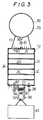
- FIG. 3 is a schematic cross section illustrating another embodiment of the apparatus for producing compressed air according to the present invention.
- FIG. 4 is a schematic cross section illustrating one embodiment of the water pumping apparatus for use in hydroelectric power generation utilizing the compressed air according to the present invention.
- FIG. 5 is a schematic cross section illustration another embodiment of the water pumping apparatus according to the present invention.
- FIGS. 1 and 2 are schematic cross-sectional views illustrating one embodiment of the apparatus for producing compressed air according to the present invention.
- the apparatus 1 includes a container body 10 having an air chamber 12 sealing air therein and is capable of reducing its volume by hydraulic pressure, a compressed air recovery vessel 30 connected to the air chamber 12 via a check valve 32 and adapted to receive the compressed air therein when the volume of the air chamber 12 is reduced by hydraulic pressure, and a weight 40 mounted on the container body 10 and adapted to sink the container body 10 and recovery vessel 30 deep under water.
- the cylindrical container body 10 has a compression piston 14 disposed therein for dividing the interior of the container body 10 and being slidable upward and downward along the inner wall of the container body 10 into the air chamber 12 and a water chamber 16 formed with a plurality of water inlet ports 18 for introducing water thereinto.
- a compression piston 14 disposed therein for dividing the interior of the container body 10 and being slidable upward and downward along the inner wall of the container body 10 into the air chamber 12 and a water chamber 16 formed with a plurality of water inlet ports 18 for introducing water thereinto.
- the compression piston 14 moves toward the air chamber 12 urged by hydraulic pressure of the water entering the water chamber 16 to thereby compress the air in the air chamber 12.
- the air chamber 12 is connected to a compressed air recovery vessel 30 through a connecting tube 34.
- the connecting tube 34 is provided with a check valve 32.
- the compressed air recovery vessel 30 has a very small volume compared with that of the air chamber 12 before being reduced in volume so that the compressed air supplied into the recovery vessel 30 can be maintained intact.
- the check valve 32 acts such that when the pressure in the air chamber 12 is higher than than in the compressed air recovery vessel 30, the air in the air chamber 12 is permitted to flow into the air recovery vessel 30 and that when the pressure relation is reversed, the compressed air in the air recovery vessel 30 does not flow back into the air chamber 12.
- the recovery vessel 30 can be detached from the container body 10 for replacement.
- FIG. 3 shows another embodiment of the apparatus for producing compressed air according to the present invention.
- the outer wall of the container body 10 can be deformed in such a manner as being expanded and contracted in the vertical direction by the external hydraulic pressure.
- the inside space of the container body 10 serves as an air chamber 12.
- the volume of the air chamber 12 can be reduced.
- the structure of the container body 10 will be described in more detail. It is constructed in a sealed state such that an upper plate 21 and a lower plate 22 are joined together through a cloth material 24 and that a plurality of annular reinforcement member 26 are sewn to the cloth member 26 so that it is expanded into a cylindrical configuration when air having a higher pressure than the atmospheric pressure is introduced into the air chamber 12.
- the cloth material 24 is formed of a material which is strong in tensile stress and water- and air-impermeable.
- the reinforcement members 26 is strong against a compressive force and is hardly deformed.
- the air chamber 12 is provided with an air inlet valve 28 adapted to take air into the air chamber 12.
- the upper plate 21 of the container body 10 is connected to a compressed air recovery vessel 30 via a connecting tube 34.
- the connecting tube 34 is provided with a check valve 32 which has the same function as the check valve 32 of the previous embodiment.
- the container body 10 of this embodimemt has a hollow cylindrical configuration, it is preferable to have a hollow spherical configuration so that it can bear the hydraulic pressure of deep sea.
- a weight 40 is detachably attached to the container body 10 in order to sink the container body 10 deep under water.
- the weight 40 is detached from the container body 10 when the volume of the air chamber 12 is reduced to the maximum possible extent by hydraulic pressure.
- the container body 10 of the embodiment shown in FIGS. 1 and 2 is provided with a buoyant body 70 so that it can float on the water by means of buoyancy when the sink weight 40 has been detached from the container body 10, whereas the compressed air recovery vessel 30 of the embodiment shown in FIG. 3 concurrently serves as a buoyant body 70, which will be described later.
- the weight 40 is accommodated within a weight mounting device 42 which comprises a casing 44 having a bottom portion 46 capable of being opened by the weight of the weight 40.
- the bottom portion 46 is closed by a wire 48 clamped by a clamping device 50 without being accidentally opened.
- the clamping device 50 comprises a spanner-like holding metal piece 52 which has clamp portions and proximal portions pivoted on a pin 54. When the proximal portions are away from each other, the clamp portions are also away from each other. One of the proximal portions is fixed to a lower part of the container body 10, whereas the other of the proximal portions is left free. Between the proximal portions a spring body 56 is interposed for biasing the free proximal portion in a direction away from the fixed proximal portion. A lock lever 58 is provided to lock the free proximal portion so as not to be away from the fixed proximal end by the biasing force of the spring body 56.
- the same clamping device 50 as in the embodiment of FIGS. 1 and 2 is used in the embodiment of FIG. 3, provided that the weight 40 is formed of a bag filled with gravel and suspended from the clamping device 50.
- both the container body 10 and the casing 4 are provided with buoyant chambers acting as the buoyant body 70. Since a compressed stress applied to the buoyant chambers becomes larger in proportion as the apparatus sinks deeper under water, the structural members constituting the buoyant chambers are required to be rigid. In order to make the difference between the internal pressure and the external pressure small as much as possible at the bottom of water at which the apparatus reaches, it is desirable to fill the buoyant chambers with compressed air in advance.
- the compressed air recovery vessel 30 is concurently as the buoyant body 70 which has a hollow spherical configuration and is connected to an upper portion of the container body 10 via rods 72. Due to the dual function of the recovery vessel 30, the pressure of the air contained therein is increased by repeating the recovery operation in view of the volume of the recovery vessel 30 and, therefore, the apparatus of FIG. 3 can bear higher hydraulic pressure in deeper water and can be suitably used for obtaining a compressed air of high pressure.
- the compression piston is pulled to the highest position and then the air recovery vessel is attached to the container body 10. After the bottom portion of the casing 44 is closed, the weight 40 is introduced into the casing 44. The casing 44 is then attached to the lower part of the container body 10. Thereafter the apparatus is hung above the surface of the sea by means of a hanging chain (not shown) and then separated from the hanging chain. As a result, the whole apparatus is sunk deep under sea by the gravity. At that time, water flows into the water chamber 16 through the water inlet ports 18 owing to hydraulic pressure to push the compression piston 14 down, thereby compressing the air in the air chamber 12.
- the air inlet valve 28 of the container body 10 is opened and the weight 40 is attached to the lower plate 22.
- air automatically flows into the air chamber 12 of the container body 10 through the air inlet valve 28 owing to the function of the weight 40 to expand the container body 10 into a cylindrical configuration.
- the valve 28 is closed.
- the weight 40 is attached to the clamping device 50 of the weight mounting device 42.
- the whole apparatus is slowly lowered onto the surface of water and separated from the crane.
- the whole apparatus slowly sinks under water.
- the hydraulic pressure increases as the apparatus sinks deep under water, air in the air chamber 12 is compressed and the air chamber 12 is reduced in volume.
- the air chamber 12 is reduced in size not in the horizontal direction because of the presence of the annular reinforcement members 26 but in the vertical direction and consequently exhibits a vertically compressed appearance as a whole.
- air in the air chamber 12 is compressed to an extent that the internal pressure is substantially equal to the external hydraulic pressure, and part of the compressed air is stored in the air recovery vessel 30.
- the volume of the air chamber 12 is further reduced by the hydraulic pressure and most of the air in the air chamber 12 is inserted under pressure into the air recovery vessel 30.
- a projection 62 attached to the upper plate 21 pushes down the unlocking pin 60 mounted on the lower plate 22 to release the locked state of the lock lever 58, and the clamping portion of the holding metal piece 52 is opened by means of biasing force of the spring body 56 to release the weight 40.
- the whole apparatus begins to float upwardly owing to the function of the recovery vessel 30.
- the recovery vessel 30 keeps a high pressure owing to the provision of the check valve 32, it is lifted by the crane when it finally floats on the surface of the water.
- the air inlet valve 28 is opened, air flows into the air chamber 12 to restore the apparatus to its original shape.
- Figs. 4 and 5 show water pumping apparatus for use in hydroelectric power generation utilizing the compressed air produced by the aforementioned compressed air production apparatus.
- the water pumping apparatus of Fig. 4 comprises a container 84 disposed between an upstream water reservoir 80 of a hydroelectric power generating apparatus (not shown) and a downstream water reservoir 82 for reserving used water.
- the interior of the container 84 is divided into an upper water tank chamber 88 and a lower air expansion chamber 90 through a piston 86 which is slidable in the vertical direction within the container 84.
- the water tank chamber 88 is connected to a water inlet tube 92 for flowing water into the water tank chamber 88 from the downstream water reservoir 82 and also to a water feed tube 94 for feeding under pressure the water reserved in the chamber 88 to the upstream water reservoir 80.
- the air expansion chamber 90 is provided with an air recovery vessel 30 containing compressed air for pushing up the piston 86 in order to expand the volume of the air expansion chamber 90.
- the recovery vessel 30 contains the compressed air recovered by the aforementioned compressed air producing apparatus.
- a first control valve 96 is disposed between the air recovery vessel 30 and the air expansion chamber 90.
- reference numeral 98 denotes a second control valve disposed at the water inlet tube 92
- numeral 100 denotes a third control valve disposed at the water feed tube 94
- numeral 102 denotes a fourth control valve disposed at an air vent pipe.
- the water pumping apparatus of Fig. 5 comprises a container 110 disposed between an upstream water reservoir 80 of a hydroelectric power generating apparatus (not shown) and a downstream water reservoir 82 for reserving the used water.
- the interior of the container 84 is divided by a partition wall 112 into a water tank chamber 114 and an air expansion chamber 116 which communicates with each other at the lower part of the container 110.
- the water tank chamber 114 is connected to a water inlet tube 92 for flowing water into the water tank chamber 114 from the downstream water reservoir 82 and also to a water feed tube 94 for feeding under pressure the water reserved in the chamber 114 to the upstream water reservoir 80,
- the air expansion chamber 116 is provided with a recovery vessel 30 containing compressed air for expanding the volume of the air expansion chamber 116.
- the apparatus of Fig. 5 is designed such that air bubbles of the compressed air to be discharged into the container 110 from the recovery vessel 30 rise upward by means of buoyancy and are pooled in the air expansion chamber 116 divided by the partition wall 112. The remaining construction thereof is the same as that of the apparatus of Fig. 4.
- used water i.e. water already subjected to hydroelectric generation
- used water i.e. water already subjected to hydroelectric generation
- the air in the air expansion chamber 90 or 116 is all drafted by opening the fourth control valve 102.
- the second and fourth control valves 98 and 102 are closed, while the third control valve 100 is opened.
- the first control valve 96 of the recovery vessel 30 is mounted to air expansion chamber 90 or 116 in a slightly open state.
- the apparatus of Fig. 4 represents a case where the piston is used.
- Fig. 5 represents a case where the piston is not used. Air bubbles of the compressed air discharged from the recovery vessel 30 rise in the water filled in the water tank chamber 114 while expanding its volume and are pooled in the air expansion chamber 116. In either case, the volume of the air expansion chamber 90 or 116 is gradually increased. Water rises through the water feed tube 94 by the amount equivalent to the increased volume of the air expansion chamber. When the tube 94 has been filled with water, the water flows into the upstream water reservoir 80.
- the third control valve 100 When the discharge of the compressed air from the recovery vessel 30 has been substantially stopped, the third control valve 100 is closed and the fourth control valve 102 is opened to draft air, and the second control valve 98 is opened to introduce the water which has already been subjected to hydroelectric power generation into the water tank chamber 88 or 114.
- the second and fourth control valves 98 and 102 When all air in the air expansion chamber 90 or 116 has been drafted, the second and fourth control valves 98 and 102 are closed, a new recovery vessel 30 is attached, the third control valve 100 is opened and then the aforementioned procedure is repeated. By repeating the aforementioned procedure, water which has already been subjected to hydroelectric power generation can be sent back to the upstream water reservoir 80, so that it can be repeatedly used for hydroelectric power generation.
Landscapes
- Engineering & Computer Science (AREA)
- Mechanical Engineering (AREA)
- General Engineering & Computer Science (AREA)
- Other Liquid Machine Or Engine Such As Wave Power Use (AREA)
- Compressors, Vaccum Pumps And Other Relevant Systems (AREA)
- Structures Of Non-Positive Displacement Pumps (AREA)
- Wind Motors (AREA)
- Jet Pumps And Other Pumps (AREA)
- Massaging Devices (AREA)
Priority Applications (1)
| Application Number | Priority Date | Filing Date | Title |
|---|---|---|---|
| EP93118570A EP0599196B1 (de) | 1990-07-03 | 1991-07-03 | Wasserpumpenvorrichtung |
Applications Claiming Priority (2)
| Application Number | Priority Date | Filing Date | Title |
|---|---|---|---|
| JP2174532A JPH0463970A (ja) | 1990-07-03 | 1990-07-03 | 水より重い大量に存在する物質を水中深く沈めて得た圧搾空気からエネルギーを得る方法 |
| JP174532/90 | 1990-07-03 |
Related Child Applications (1)
| Application Number | Title | Priority Date | Filing Date |
|---|---|---|---|
| EP93118570.6 Division-Into | 1993-11-18 |
Publications (2)
| Publication Number | Publication Date |
|---|---|
| EP0465242A1 true EP0465242A1 (de) | 1992-01-08 |
| EP0465242B1 EP0465242B1 (de) | 1995-10-04 |
Family
ID=15980178
Family Applications (2)
| Application Number | Title | Priority Date | Filing Date |
|---|---|---|---|
| EP93118570A Expired - Lifetime EP0599196B1 (de) | 1990-07-03 | 1991-07-03 | Wasserpumpenvorrichtung |
| EP91306057A Expired - Lifetime EP0465242B1 (de) | 1990-07-03 | 1991-07-03 | Verfahren und Vorrichtung zur Erzeugung komprimierter Luft |
Family Applications Before (1)
| Application Number | Title | Priority Date | Filing Date |
|---|---|---|---|
| EP93118570A Expired - Lifetime EP0599196B1 (de) | 1990-07-03 | 1991-07-03 | Wasserpumpenvorrichtung |
Country Status (8)
| Country | Link |
|---|---|
| US (2) | US5205720A (de) |
| EP (2) | EP0599196B1 (de) |
| JP (1) | JPH0463970A (de) |
| AT (2) | ATE128754T1 (de) |
| AU (1) | AU645102B2 (de) |
| CA (1) | CA2086089C (de) |
| DE (2) | DE69118210T2 (de) |
| WO (1) | WO1992001154A1 (de) |
Cited By (5)
| Publication number | Priority date | Publication date | Assignee | Title |
|---|---|---|---|---|
| ES2100780A2 (es) * | 1993-01-28 | 1997-06-16 | Parellada Borda Juan | Instalacion de obtencion de aire comprimido |
| WO2000070221A1 (fr) * | 1999-05-14 | 2000-11-23 | Shuanglai Yang | Pompe de compression hydraulique |
| AT513180A1 (de) * | 2012-07-26 | 2014-02-15 | Piotrowski Maksym | Antriebseinrichtung zum Antreiben eines Generators |
| WO2015079462A1 (en) * | 2013-11-29 | 2015-06-04 | Sel Sistemi Energetici Lucani Srl | Lifting device for hydroelectric power plants |
| CN109404221A (zh) * | 2018-11-19 | 2019-03-01 | 丘骏豪 | 一种风能驱动的空气压缩型野外淡水节能收集过滤装置 |
Families Citing this family (20)
| Publication number | Priority date | Publication date | Assignee | Title |
|---|---|---|---|---|
| JPH0463970A (ja) | 1990-07-03 | 1992-02-28 | Tsuguo Nagata | 水より重い大量に存在する物質を水中深く沈めて得た圧搾空気からエネルギーを得る方法 |
| JP2684470B2 (ja) * | 1991-07-29 | 1997-12-03 | 二生 永田 | 圧縮空気の作成方法及び作成装置 |
| JP2684471B2 (ja) * | 1991-07-29 | 1997-12-03 | 二生 永田 | 圧縮空気の作成方法及び作成装置 |
| US20030145589A1 (en) * | 2001-12-17 | 2003-08-07 | Tillyer Joseph P. | Fluid displacement method and apparatus |
| TW499543B (en) * | 2001-12-18 | 2002-08-21 | Ming-Hung Lin | Bellows type electric power generating equipment using sea wave |
| WO2004019476A2 (en) * | 2002-08-21 | 2004-03-04 | Am. S. Islam | A process of obtaining electricity through transfer of mass |
| US6907933B2 (en) * | 2003-02-13 | 2005-06-21 | Conocophillips Company | Sub-sea blow case compressor |
| US7377492B2 (en) * | 2004-08-11 | 2008-05-27 | A Better Power, Llc | Hydraulic liquid pumping system |
| US20060267346A1 (en) * | 2005-05-27 | 2006-11-30 | Tien-Chuan Chen | Hydraulic power plant driven by gravity and buoyancy circulation |
| JP2013506098A (ja) * | 2009-09-23 | 2013-02-21 | レイモンド フレイジャー,スコット | 水中に圧縮流体エネルギを貯蔵するシステムおよび同システムを配置する方法 |
| US8147212B2 (en) * | 2009-12-24 | 2012-04-03 | Roland Lawes | Wave driven air compressor |
| CA2804910A1 (en) * | 2010-03-01 | 2011-09-09 | Brian Von Herzen | Apparatus for storage vessel deployment and method of making same |
| CA2804806C (en) | 2010-07-14 | 2018-10-30 | Bright Energy Storage Technologies, Llp | System and method for storing thermal energy |
| DE102012015732B4 (de) | 2011-08-27 | 2015-07-09 | Hans Martin Giese | Verfahren und Anordnungen zur Aufnahme und Abgabe elektrischer Energie in Gasdruckspeicherwerken |
| CN104265592A (zh) * | 2013-02-25 | 2015-01-07 | 赵彦杰 | 塑料打压泵 |
| FR3016930B1 (fr) * | 2014-01-28 | 2016-02-05 | Christophe Stevens | Systeme de stockage et generation d'energie electrique pour milieu aquatique |
| CN104747137B (zh) * | 2015-01-04 | 2017-07-04 | 任丘市本溪石油设备有限公司 | 悬绳式套管气回收装置 |
| CN108397275A (zh) * | 2018-04-19 | 2018-08-14 | 精进电动科技股份有限公司 | 一种梯度式汽车膨胀水箱 |
| CN109441893B (zh) * | 2018-12-19 | 2023-06-20 | 贵州创能科技有限公司 | 一种水压气泵 |
| TW202115314A (zh) * | 2019-10-01 | 2021-04-16 | 玉鼎興業有限公司 | 抽水裝置 |
Citations (6)
| Publication number | Priority date | Publication date | Assignee | Title |
|---|---|---|---|---|
| US2840004A (en) * | 1955-06-13 | 1958-06-24 | Phillips Petroleum Co | Pump |
| DE2406756A1 (de) * | 1974-02-13 | 1975-05-15 | Harald Dr Ing Kayser | Hydroelektrischer wellengenerator |
| US4426846A (en) * | 1978-04-24 | 1984-01-24 | Wayne Bailey | Hydraulic power plant |
| JPS60190679A (ja) | 1984-03-12 | 1985-09-28 | Masao Kanazawa | 重力・浮力差による空気圧縮装置 |
| EP0192246A2 (de) * | 1985-02-19 | 1986-08-27 | The Coca-Cola Company | Durch Gas angetriebene einfach wirkende Pumpe |
| EP0599196A1 (de) | 1990-07-03 | 1994-06-01 | Tsugio Nagata | Wasserpumpenvorrichtung |
Family Cites Families (23)
| Publication number | Priority date | Publication date | Assignee | Title |
|---|---|---|---|---|
| US43770A (en) * | 1864-08-09 | Improvement in apparatus for forcing water by pneumatic pressure | ||
| US583837A (en) * | 1897-06-01 | Compressed-air water-elevator | ||
| US341021A (en) * | 1886-05-04 | Mechanism for utilizing wave-power | ||
| US51908A (en) * | 1866-01-09 | Improvement in steam water-elevators | ||
| US643863A (en) * | 1898-05-24 | 1900-02-20 | William S Bryant | Floating pump. |
| US631994A (en) * | 1899-05-29 | 1899-08-29 | Leverett Bell | Air-compressor. |
| US778608A (en) * | 1903-12-23 | 1904-12-27 | John Rogers | Automatic air-compressor. |
| US1005616A (en) * | 1911-02-28 | 1911-10-10 | Gabriel Heinrich William Doose | Wave-motor. |
| US1091313A (en) * | 1912-06-18 | 1914-03-24 | Carl H Erickson | Air-compressor. |
| US1455718A (en) * | 1921-12-16 | 1923-05-15 | Nelson M Delong | Hydropneumatic device |
| US1616017A (en) * | 1925-04-08 | 1927-02-01 | Martin E Williams | Well pump |
| US2050526A (en) * | 1935-09-26 | 1936-08-11 | Joe H Gleason | Fluid lift pump |
| US2171402A (en) * | 1938-09-19 | 1939-08-29 | Wallace P Strait | Fluid well flowing means |
| US2520398A (en) * | 1947-03-21 | 1950-08-29 | Harold M Hanks | Oil dispensing pump |
| US4265599A (en) * | 1979-01-31 | 1981-05-05 | Morton Paul H | Hydropneumatic energy system |
| JPS56113059A (en) * | 1980-02-07 | 1981-09-05 | Eishin Nakamura | Storage device of wave energy |
| JPS60104779A (ja) * | 1983-11-14 | 1985-06-10 | Takenaka Komuten Co Ltd | 定圧化タンク方式の波力発電方法 |
| JPS60111065A (ja) * | 1983-11-18 | 1985-06-17 | Toshihiko Narahara | 水圧エネルギ−を圧力空気エネルギ−として採取するシステム |
| JPS60113059A (ja) * | 1983-11-25 | 1985-06-19 | Suzuki Motor Co Ltd | V型エンジンの吸気装置 |
| JPS60224978A (ja) * | 1984-04-23 | 1985-11-09 | Kenji Wakayama | 液体中における浮力・重力併用発動方法とその装置 |
| JPS6241974A (ja) * | 1984-11-30 | 1987-02-23 | Koichi Nishikawa | 波力発電装置 |
| JPS6414426A (en) * | 1987-07-06 | 1989-01-18 | Space Prod Co Ltd | Packing work for temporary column draw hole and drop piece therefor |
| JPS6420313A (en) * | 1987-07-10 | 1989-01-24 | Nippon Catalytic Chem Ind | Viscose rayon improved in dyeability |
-
1990
- 1990-07-03 JP JP2174532A patent/JPH0463970A/ja active Pending
-
1991
- 1991-07-02 WO PCT/JP1991/000892 patent/WO1992001154A1/ja not_active Ceased
- 1991-07-02 CA CA002086089A patent/CA2086089C/en not_active Expired - Fee Related
- 1991-07-02 AU AU80796/91A patent/AU645102B2/en not_active Ceased
- 1991-07-03 AT AT91306057T patent/ATE128754T1/de not_active IP Right Cessation
- 1991-07-03 US US07/725,662 patent/US5205720A/en not_active Expired - Lifetime
- 1991-07-03 DE DE69118210T patent/DE69118210T2/de not_active Expired - Fee Related
- 1991-07-03 EP EP93118570A patent/EP0599196B1/de not_active Expired - Lifetime
- 1991-07-03 DE DE69113533T patent/DE69113533T2/de not_active Expired - Fee Related
- 1991-07-03 EP EP91306057A patent/EP0465242B1/de not_active Expired - Lifetime
- 1991-07-03 AT AT93118570T patent/ATE135797T1/de active
-
1993
- 1993-09-30 US US08/129,577 patent/US5340283A/en not_active Expired - Fee Related
Patent Citations (6)
| Publication number | Priority date | Publication date | Assignee | Title |
|---|---|---|---|---|
| US2840004A (en) * | 1955-06-13 | 1958-06-24 | Phillips Petroleum Co | Pump |
| DE2406756A1 (de) * | 1974-02-13 | 1975-05-15 | Harald Dr Ing Kayser | Hydroelektrischer wellengenerator |
| US4426846A (en) * | 1978-04-24 | 1984-01-24 | Wayne Bailey | Hydraulic power plant |
| JPS60190679A (ja) | 1984-03-12 | 1985-09-28 | Masao Kanazawa | 重力・浮力差による空気圧縮装置 |
| EP0192246A2 (de) * | 1985-02-19 | 1986-08-27 | The Coca-Cola Company | Durch Gas angetriebene einfach wirkende Pumpe |
| EP0599196A1 (de) | 1990-07-03 | 1994-06-01 | Tsugio Nagata | Wasserpumpenvorrichtung |
Non-Patent Citations (2)
| Title |
|---|
| PATENT ABSTRACTS OF JAPAN vol. 10, no. 37 (M-453)February 14, 1986 & JP-A-60 190 679 (MASAO KANAZAWA ) September 28, 1985 * |
| PATENT ABSTRACTS OF JAPAN vol. 10, no. 83 (M-466)(2140) April 2, 1986 & JP-A-60 224 978 (KENJI WAKAYAMA ) November 9, 1985 * |
Cited By (7)
| Publication number | Priority date | Publication date | Assignee | Title |
|---|---|---|---|---|
| ES2100780A2 (es) * | 1993-01-28 | 1997-06-16 | Parellada Borda Juan | Instalacion de obtencion de aire comprimido |
| WO2000070221A1 (fr) * | 1999-05-14 | 2000-11-23 | Shuanglai Yang | Pompe de compression hydraulique |
| AT513180A1 (de) * | 2012-07-26 | 2014-02-15 | Piotrowski Maksym | Antriebseinrichtung zum Antreiben eines Generators |
| AT513180B1 (de) * | 2012-07-26 | 2018-04-15 | Maksym Piotrowski | Antriebseinrichtung zum Antreiben eines Generators |
| WO2015079462A1 (en) * | 2013-11-29 | 2015-06-04 | Sel Sistemi Energetici Lucani Srl | Lifting device for hydroelectric power plants |
| CN109404221A (zh) * | 2018-11-19 | 2019-03-01 | 丘骏豪 | 一种风能驱动的空气压缩型野外淡水节能收集过滤装置 |
| CN109404221B (zh) * | 2018-11-19 | 2020-10-09 | 丘骏豪 | 一种风能驱动的空气压缩型野外淡水节能收集过滤装置 |
Also Published As
| Publication number | Publication date |
|---|---|
| DE69118210T2 (de) | 1996-07-18 |
| WO1992001154A1 (en) | 1992-01-23 |
| EP0599196A1 (de) | 1994-06-01 |
| DE69118210D1 (de) | 1996-04-25 |
| DE69113533D1 (de) | 1995-11-09 |
| US5340283A (en) | 1994-08-23 |
| CA2086089C (en) | 1999-01-05 |
| AU645102B2 (en) | 1994-01-06 |
| AU8079691A (en) | 1992-02-04 |
| EP0465242B1 (de) | 1995-10-04 |
| DE69113533T2 (de) | 1996-02-29 |
| JPH0463970A (ja) | 1992-02-28 |
| EP0599196B1 (de) | 1996-03-20 |
| US5205720A (en) | 1993-04-27 |
| ATE135797T1 (de) | 1996-04-15 |
| CA2086089A1 (en) | 1992-01-04 |
| ATE128754T1 (de) | 1995-10-15 |
Similar Documents
| Publication | Publication Date | Title |
|---|---|---|
| EP0465242A1 (de) | Verfahren und Vorrichtung zur Erzeugung komprimierter Luft | |
| US6964165B2 (en) | System and process for recovering energy from a compressed gas | |
| US3587227A (en) | Power generating means | |
| EP0265594B1 (de) | Schwimmervorrichtung zur Förderung der Wellenenergie | |
| US7911073B2 (en) | System and method for a hydro-hydraulic gravitational generator | |
| US10364938B2 (en) | Underwater energy storage using compressed fluid | |
| US20080092535A1 (en) | Systems and methods using gravity and buoyancy for producing energy | |
| US4163633A (en) | Apparatus for producing power from water waves | |
| US4433633A (en) | Controlled gas generator system | |
| FR2800423A1 (fr) | Pompe a piston aspirante-refoulante immergee pour liquides activee par l'energie d'agitation de son milieu d'immersion | |
| CN111307515A (zh) | 海底间歇性水样采集装置 | |
| GB2027815A (en) | Wave energy conversion apparatus | |
| US6945042B1 (en) | System for generating fluid movement | |
| CN1199822A (zh) | 海浪发电装置 | |
| CA2224054C (en) | Water pumping apparatus utilizing compressed air | |
| JPS61182473A (ja) | 気体浮力を応用せる給気式動力発生装置 | |
| WO2010076797A2 (en) | Apparatus with buoyant and sinkable piston | |
| JPH0560049A (ja) | 圧縮空気を利用した水力発電における揚水装置 | |
| CN119213251A (zh) | 用于储存能量的外部压力流体储存器 | |
| JP2684471B2 (ja) | 圧縮空気の作成方法及び作成装置 | |
| CN111307516A (zh) | 海底定点水样采集装置 | |
| CN214397144U (zh) | 无人直升机海上迫降装置 | |
| US4126191A (en) | Gas discharge type underwater hammer with liquid purge and reflood control | |
| JPS60190679A (ja) | 重力・浮力差による空気圧縮装置 | |
| JPH03124973A (ja) | 波動ポンプ装置および方法 |
Legal Events
| Date | Code | Title | Description |
|---|---|---|---|
| PUAI | Public reference made under article 153(3) epc to a published international application that has entered the european phase |
Free format text: ORIGINAL CODE: 0009012 |
|
| AK | Designated contracting states |
Kind code of ref document: A1 Designated state(s): AT DE FR GB GR IT SE |
|
| 17P | Request for examination filed |
Effective date: 19920619 |
|
| 17Q | First examination report despatched |
Effective date: 19930727 |
|
| GRAA | (expected) grant |
Free format text: ORIGINAL CODE: 0009210 |
|
| AK | Designated contracting states |
Kind code of ref document: B1 Designated state(s): AT DE FR GB GR IT SE |
|
| PG25 | Lapsed in a contracting state [announced via postgrant information from national office to epo] |
Ref country code: GR Free format text: LAPSE BECAUSE OF FAILURE TO SUBMIT A TRANSLATION OF THE DESCRIPTION OR TO PAY THE FEE WITHIN THE PRESCRIBED TIME-LIMIT Effective date: 19951004 Ref country code: IT Free format text: LAPSE BECAUSE OF FAILURE TO SUBMIT A TRANSLATION OF THE DESCRIPTION OR TO PAY THE FEE WITHIN THE PRE;WARNING: LAPSES OF ITALIAN PATENTS WITH EFFECTIVE DATE BEFORE 2007 MAY HAVE OCCURRED AT ANY TIME BEFORE 2007. THE CORRECT EFFECTIVE DATE MAY BE DIFFERENT FROM THE ONE RECORDED.SCRIBED TIME-LIMIT Effective date: 19951004 Ref country code: AT Effective date: 19951004 |
|
| REF | Corresponds to: |
Ref document number: 128754 Country of ref document: AT Date of ref document: 19951015 Kind code of ref document: T |
|
| XX | Miscellaneous (additional remarks) |
Free format text: TEILANMELDUNG 93118570.6 EINGEREICHT AM 03/07/91. |
|
| REF | Corresponds to: |
Ref document number: 69113533 Country of ref document: DE Date of ref document: 19951109 |
|
| PG25 | Lapsed in a contracting state [announced via postgrant information from national office to epo] |
Ref country code: SE Effective date: 19960104 |
|
| ET | Fr: translation filed | ||
| PLBE | No opposition filed within time limit |
Free format text: ORIGINAL CODE: 0009261 |
|
| STAA | Information on the status of an ep patent application or granted ep patent |
Free format text: STATUS: NO OPPOSITION FILED WITHIN TIME LIMIT |
|
| 26N | No opposition filed | ||
| PGFP | Annual fee paid to national office [announced via postgrant information from national office to epo] |
Ref country code: DE Payment date: 20000703 Year of fee payment: 10 |
|
| PGFP | Annual fee paid to national office [announced via postgrant information from national office to epo] |
Ref country code: FR Payment date: 20000711 Year of fee payment: 10 |
|
| REG | Reference to a national code |
Ref country code: GB Ref legal event code: IF02 |
|
| PG25 | Lapsed in a contracting state [announced via postgrant information from national office to epo] |
Ref country code: FR Free format text: LAPSE BECAUSE OF NON-PAYMENT OF DUE FEES Effective date: 20020329 |
|
| PG25 | Lapsed in a contracting state [announced via postgrant information from national office to epo] |
Ref country code: DE Free format text: LAPSE BECAUSE OF NON-PAYMENT OF DUE FEES Effective date: 20020501 |
|
| REG | Reference to a national code |
Ref country code: FR Ref legal event code: ST |
|
| PGFP | Annual fee paid to national office [announced via postgrant information from national office to epo] |
Ref country code: GB Payment date: 20040630 Year of fee payment: 14 |
|
| PG25 | Lapsed in a contracting state [announced via postgrant information from national office to epo] |
Ref country code: GB Free format text: LAPSE BECAUSE OF NON-PAYMENT OF DUE FEES Effective date: 20050703 |
|
| GBPC | Gb: european patent ceased through non-payment of renewal fee |
Effective date: 20050703 |