EP0465290A1 - Condensateur de puissance - Google Patents
Condensateur de puissance Download PDFInfo
- Publication number
- EP0465290A1 EP0465290A1 EP91401635A EP91401635A EP0465290A1 EP 0465290 A1 EP0465290 A1 EP 0465290A1 EP 91401635 A EP91401635 A EP 91401635A EP 91401635 A EP91401635 A EP 91401635A EP 0465290 A1 EP0465290 A1 EP 0465290A1
- Authority
- EP
- European Patent Office
- Prior art keywords
- metallized
- dielectric
- film
- winding
- capacitor according
- Prior art date
- Legal status (The legal status is an assumption and is not a legal conclusion. Google has not performed a legal analysis and makes no representation as to the accuracy of the status listed.)
- Granted
Links
- 239000003990 capacitor Substances 0.000 title claims abstract description 39
- 239000007788 liquid Substances 0.000 claims abstract description 13
- 229920006255 plastic film Polymers 0.000 claims abstract description 9
- 239000002985 plastic film Substances 0.000 claims abstract description 9
- 239000010408 film Substances 0.000 claims description 20
- 238000004804 winding Methods 0.000 claims description 15
- 238000005470 impregnation Methods 0.000 claims description 13
- 239000011104 metalized film Substances 0.000 claims description 11
- 239000002184 metal Substances 0.000 claims description 8
- 229910052751 metal Inorganic materials 0.000 claims description 8
- 238000004519 manufacturing process Methods 0.000 claims description 7
- 239000011810 insulating material Substances 0.000 claims description 6
- 238000000034 method Methods 0.000 claims description 4
- 229920006254 polymer film Polymers 0.000 claims description 3
- 238000010025 steaming Methods 0.000 claims description 3
- 235000013311 vegetables Nutrition 0.000 claims description 3
- 239000000654 additive Substances 0.000 claims description 2
- 235000008429 bread Nutrition 0.000 description 9
- 239000004743 Polypropylene Substances 0.000 description 4
- 238000001465 metallisation Methods 0.000 description 4
- -1 polypropylene Polymers 0.000 description 4
- 229920001155 polypropylene Polymers 0.000 description 4
- 230000008929 regeneration Effects 0.000 description 4
- 238000011069 regeneration method Methods 0.000 description 4
- 239000004593 Epoxy Substances 0.000 description 3
- IJGRMHOSHXDMSA-UHFFFAOYSA-N Atomic nitrogen Chemical compound N#N IJGRMHOSHXDMSA-UHFFFAOYSA-N 0.000 description 2
- RYGMFSIKBFXOCR-UHFFFAOYSA-N Copper Chemical compound [Cu] RYGMFSIKBFXOCR-UHFFFAOYSA-N 0.000 description 2
- 235000019484 Rapeseed oil Nutrition 0.000 description 2
- HCHKCACWOHOZIP-UHFFFAOYSA-N Zinc Chemical compound [Zn] HCHKCACWOHOZIP-UHFFFAOYSA-N 0.000 description 2
- 229910052782 aluminium Inorganic materials 0.000 description 2
- XAGFODPZIPBFFR-UHFFFAOYSA-N aluminium Chemical compound [Al] XAGFODPZIPBFFR-UHFFFAOYSA-N 0.000 description 2
- 238000004140 cleaning Methods 0.000 description 2
- 239000000463 material Substances 0.000 description 2
- QSHDDOUJBYECFT-UHFFFAOYSA-N mercury Chemical compound [Hg] QSHDDOUJBYECFT-UHFFFAOYSA-N 0.000 description 2
- 229910052753 mercury Inorganic materials 0.000 description 2
- 238000005096 rolling process Methods 0.000 description 2
- 239000011701 zinc Substances 0.000 description 2
- 229910000831 Steel Inorganic materials 0.000 description 1
- 239000002671 adjuvant Substances 0.000 description 1
- 238000000637 aluminium metallisation Methods 0.000 description 1
- PNEYBMLMFCGWSK-UHFFFAOYSA-N aluminium oxide Inorganic materials [O-2].[O-2].[O-2].[Al+3].[Al+3] PNEYBMLMFCGWSK-UHFFFAOYSA-N 0.000 description 1
- 239000003963 antioxidant agent Substances 0.000 description 1
- 230000003078 antioxidant effect Effects 0.000 description 1
- 125000003118 aryl group Chemical group 0.000 description 1
- 230000015572 biosynthetic process Effects 0.000 description 1
- 239000002775 capsule Substances 0.000 description 1
- 239000007795 chemical reaction product Substances 0.000 description 1
- 239000000470 constituent Substances 0.000 description 1
- 238000010411 cooking Methods 0.000 description 1
- 229910052802 copper Inorganic materials 0.000 description 1
- 239000010949 copper Substances 0.000 description 1
- 239000011889 copper foil Substances 0.000 description 1
- 238000007599 discharging Methods 0.000 description 1
- 238000009826 distribution Methods 0.000 description 1
- 239000004744 fabric Substances 0.000 description 1
- 239000011521 glass Substances 0.000 description 1
- 238000007654 immersion Methods 0.000 description 1
- 239000007769 metal material Substances 0.000 description 1
- 239000000203 mixture Substances 0.000 description 1
- 229910052757 nitrogen Inorganic materials 0.000 description 1
- 239000005026 oriented polypropylene Substances 0.000 description 1
- 230000000149 penetrating effect Effects 0.000 description 1
- 239000004033 plastic Substances 0.000 description 1
- 238000002360 preparation method Methods 0.000 description 1
- 230000000135 prohibitive effect Effects 0.000 description 1
- 238000005476 soldering Methods 0.000 description 1
- 238000005507 spraying Methods 0.000 description 1
- 229910001220 stainless steel Inorganic materials 0.000 description 1
- 239000010935 stainless steel Substances 0.000 description 1
- 239000010959 steel Substances 0.000 description 1
- 238000003786 synthesis reaction Methods 0.000 description 1
- 238000011282 treatment Methods 0.000 description 1
- 238000003466 welding Methods 0.000 description 1
- 229910052725 zinc Inorganic materials 0.000 description 1
Images
Classifications
-
- H—ELECTRICITY
- H01—ELECTRIC ELEMENTS
- H01G—CAPACITORS; CAPACITORS, RECTIFIERS, DETECTORS, SWITCHING DEVICES, LIGHT-SENSITIVE OR TEMPERATURE-SENSITIVE DEVICES OF THE ELECTROLYTIC TYPE
- H01G4/00—Fixed capacitors; Processes of their manufacture
- H01G4/38—Multiple capacitors, i.e. structural combinations of fixed capacitors
-
- H—ELECTRICITY
- H01—ELECTRIC ELEMENTS
- H01G—CAPACITORS; CAPACITORS, RECTIFIERS, DETECTORS, SWITCHING DEVICES, LIGHT-SENSITIVE OR TEMPERATURE-SENSITIVE DEVICES OF THE ELECTROLYTIC TYPE
- H01G4/00—Fixed capacitors; Processes of their manufacture
- H01G4/002—Details
- H01G4/018—Dielectrics
- H01G4/20—Dielectrics using combinations of dielectrics from more than one of groups H01G4/02 - H01G4/06
- H01G4/22—Dielectrics using combinations of dielectrics from more than one of groups H01G4/02 - H01G4/06 impregnated
-
- H—ELECTRICITY
- H01—ELECTRIC ELEMENTS
- H01G—CAPACITORS; CAPACITORS, RECTIFIERS, DETECTORS, SWITCHING DEVICES, LIGHT-SENSITIVE OR TEMPERATURE-SENSITIVE DEVICES OF THE ELECTROLYTIC TYPE
- H01G4/00—Fixed capacitors; Processes of their manufacture
- H01G4/32—Wound capacitors
Definitions
- the present invention relates to a power capacitor, more particularly a power capacitor of the type constituted by at least one capacitive element obtained by winding at least two metallized dielectric films.
- the present invention relates more particularly to power capacitors of the above type used in the filter elements mounted on rolling or fixed equipment.
- Such capacitors must have a very high specific energy, generally greater than 100 Joules / liter, be as light as possible and withstand significant vibration constraints.
- the present invention aims to provide a new type of power capacitor having a non-negligible specific energy as well as a significantly improved operating gradient compared to the capacitors of the prior art.
- the subject of the present invention is a power capacitor of the type constituted by at least one capacitive element obtained by winding at least two films.
- metallized dielectric characterized in that the dielectric film is constituted by a plastic film, in that the capacitive element is flattened so as to form a flat element having a guaranteed thickness in that the flat element is impregnated with a liquid dielectric and in that the metallized film has aliasing formed by local demetallizations of the metallized film.
- the plastic film is a polymer film with a rough surface, the use of a rough surface allowing better impregnation.
- the aliasing can consist of straight or T-shaped slots.
- the liquid dielectric consists essentially of a vegetable type dielectric. Indeed, such a dielectric does not damage the aluminum metallization and penetrates very little the polypropylene plastic film.
- the capacitive element or elements constituting the capacitor are mounted in a metal tank with interposition of shims made of insulating material.
- the shims made of insulating material make it possible to absorb vibrations in the case where the capacitor is mounted on rolling stock such as trains, and the tank made of metallic material makes it possible to earth the capacitor.
- a non-metallized dielectric film is inserted between two metallized films.
- the capacitive element or elements constituting the power capacitor are obtained by winding around a pin M of at least two films 1 having metallized zones 2 and on their opposite edges non-metallized margins 3.
- the metallized film used in the context of the present invention is a polymer film, more particularly a bi-oriented polypropylene film.
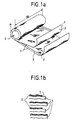
- the polypropylene film is preferably, as shown in FIG. 1B, a rough film. It can be rough on one side or rough on the two sides.
- this corona pretreated film was metallized using a metal such as aluminum in a vacuum metallization apparatus (resistivity of metallization 1 to 5 ⁇ ⁇ ).
- a metallized film is used having aliasing formed by local demetallizations of the metallized film.
- aliasing makes it possible, inter alia, to improve self-healing and the test results have shown that a better nominal operating gradient is thus obtained.
- the two metallized films are wound by being offset with respect to each other.
- a rough non-metallized plastic film is inserted between the two films over approximately 2 turns at the start and end of the winding.
- the winding is carried out around the spindle with a continuous overrun of the expansion.
- this control will be such that an outer diameter of the coil on the mandrel M is obtained, corresponding to an expansion of approximately 15% relative to the weight thickness of the metallized film.
- expansion we mean the inter-space given by the winding between the layers. To obtain a good impregnation and good preformances, the expansion must be as constant as possible.
- the cylindrical capacitive element C thus obtained is extracted from the spindle M, it is flattened and put into press at a mechanical dimension corresponding to an overrun of 12% in the embodiment shown so as to obtain a flat element C 'as shown in FIG. 2.
- the use of flat elements makes it possible to obtain elements whose thickness e is perfectly controlled, that is to say elements whose expansion is completely determined.
- the bread of flat elements is subjected to baking in a vacuum oven.
- this cooking is carried out at a temperature of about 80 ° C under a vacuum of less than 10 ⁇ 2mm Hg.
- the bread is left in the oven for 24 hours.
- the temperature is brought down to 20 ° C and the breads are left for 16 hours before taking them out at room temperature.
- the various flat elements are prepared so that the side terminations can be shooped.
- the shooping is carried out in a known manner by spraying a metal such as zinc onto a surface 6 (layer thickness of Zn: 0.6 ⁇ m).
- the various capacitive elements C are wired.
- This wiring operation is carried out after cleaning the loaves so as to eliminate the zinc dust. This cleaning takes place for example by sending compressed air at a pressure of 4 bars.
- the actual wiring of the various elements is then carried out. This wiring is carried out by first soldering a tinned copper foil on the middle part which aims to stiffen all of the bread. Then a copper braid 9 is welded on each element.
- the connections of the different elements are made symmetrically at the top and bottom of the median for each half-loaf so as to obtain a better distribution of the currents.
- the capacitive elements are mounted in parallel. It is obvious to those skilled in the art that the capacitive elements can be mounted in parallel and / or in series.
- connection wire 10 is soldered to the part 8. This connection wire is intended to connect the capacitive bar to the external connection terminal, as shown in FIG. 4.
- the first test consists in discharging in each bread a ballast energy of, for example, 62 Joules, which corresponds to the charge under 500 Volts of a capacitor of 500 ⁇ F. This test enables short circuiting to be carried out.
- Each bread is charged at a DC voltage corresponding to a gradient on the film of, for example, 200V / ⁇ . This voltage is applied for a time of approximately 10 seconds. During this time, there is therefore a significant number of regenerations. If regeneration is not stabilized after 30 seconds, the bread is considered unusable.
- the bread is then ready to be mounted in a tank as shown in FIG. 4.
- a metal parallelepiped box made for example of steel, stainless steel or aluminum, is used as the tank.
- the metal housing makes it easy to ground the capacitor and is used for safety reasons.
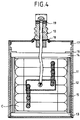
- the metal tank 11 is lined internally with plates 12, 13 and a retaining plate 14 inserted later, made of insulating materials, for example polypropylene. These plates of insulating materials serve to electrically insulate the bun (s) from the tank.
- the plate 13, disposed at the bottom of the tank has a thickness of 10mm while the lateral profiles 12 have a thickness of 2mm.
- one or more bars of capacitive elements C ′ are introduced into the metal tank 11 and are wedged with one or more sets of plates 15 also made of insulating materials.
- the setting of the bun (s) inside the tank is essential for the capacitive elements to withstand the vibrations.
- the holding plate 14 is then introduced.
- Two brackets 16 are then welded to the top of the tank to immobilize the assembly.
- the tank is provided with a cover 17 having an opening 18 for the passage of the connection terminals 19 and the impregnation.
- a liquid dielectric preferably a vegetable type dielectric such as rapeseed oil which has the main advantage of not damaging the metallization and of penetrating the polypropylene film very slightly.
- Impregnation takes place in two phases.
- the condenser is first dried, preferably at a temperature of 50 ° C under a vacuum of 10 ⁇ 2mm of mercury. It is considered that the capacitor is properly dried when the 50 ° C / 10 ⁇ 2mm Hg torque has been reached for 24 hours.
- the liquid is degassed under vacuum, at 60 ° C., and it is decontaminated on earth materials or on an activated alumina column.
- the liquid is then admitted into the vacuum impregnation tank at 10 ⁇ 2mm of mercury.
- the capacitive rolls are then impregnated by immersion.
- the capacitor is considered to be completely impregnated when the increase in capacity over eight hours does not exceed 1%.
- the vacuum is broken under nitrogen at atmospheric pressure and the temperature is then cut.
- the capacitors thus obtained are then subjected to end-of-production controls of the conventional type, such as leakage tests, electrical controls at ambient temperature and finishing treatments.
Landscapes
- Engineering & Computer Science (AREA)
- Power Engineering (AREA)
- Manufacturing & Machinery (AREA)
- Microelectronics & Electronic Packaging (AREA)
- Fixed Capacitors And Capacitor Manufacturing Machines (AREA)
- Ceramic Capacitors (AREA)
- Oscillators With Electromechanical Resonators (AREA)
- Electrical Discharge Machining, Electrochemical Machining, And Combined Machining (AREA)
- Curing Cements, Concrete, And Artificial Stone (AREA)
- Lubricants (AREA)
Abstract
Description
- La présente invention concerne un condensateur de puissance, plus particulièrement un condensateur de puissance du type constitué par au moins un élément capacitif obtenu par bobinage d'au moins deux films diélectriques métallisés. En fait la présente invention concerne plus particulièrement des condensateurs de puissance du type ci-dessus utilisés dans les éléments de filtrage montés sur du matériel roulant ou fixe. De tels condensateurs doivent présenter une énergie spécifique très importante, en général supérieure à 100 Joules/litre, être le plus léger possible et résister à des contraintes de vibrations non négligeables.
- Actuellement les condensateurs de puissance de ce type sont obtenus en utilisant comme film diélectrique du papier métallisé, ce papier métallisé étant imprégné à la cire. Or le papier métallisé est un constituant cher, ce qui entraîne un coût de fabrication des condensateurs qui devient prohibitif. D'autre part, la densité du papier métallisé est d'environ 1,3, ce qui donne un produit final lourd. De plus, du fait de l'imprégnation à la cire ainsi que du type de film diélectrique utilisé, les performances des condensateurs sont limitées en température et en tension.
- En conséquence, notamment pour les applications spécifiques mentionnées ci-dessus, la Demanderesse a cherché à fabriquer des condensateurs de puissance en utilisant d'autres types de matériaux que le papier métallisé imprégné à la cire.
- Ainsi, la présente invention a pour but de fournir un nouveau type de condensateur de puissance présentant une énergie spécifique non négligeable ainsi qu'un gradient de fonctionnement nettement amélioré par rapport aux condensateurs de l'art antérieur.
- En conséquence, la présente invention a pour objet un condensateur de puissance du type constitué par au moins un élément capacitif obtenu par bobinage d'au moins deux films diélectriques métallisés, caractérisé en ce que le film diélectrique est constitué par un film plastique, en ce que l'élément capacitif est aplati de manière à former un élément plat présentant une épaisseur garantie en ce que l'élément plat est imprégné par un diélectrique liquide et en ce que le film métallisé présente un crénelage formé par des démétallisations locales du film métallisé.
- Selon un mode de réalisation préférentiel, le film plastique est un film polymère à surface rugueuse, l'utilisation d'une surface rugueuse permettant une meilleure imprégnation. De plus, le crénelage peut être constitué par des créneaux droits ou en forme de T.
- D'autre part, le diélectrique liquide est constitué, essentiellement, par un diélectrique de type végétal. En effet, un tel diélectrique n'abîme pas la métallisation aluminium et pénètre très faiblement le film plastique polypropylène.
- Selon une autre caractéristique de la présente invention, pour des questions de sécurité, le ou les éléments capacitifs constituant le condensateur sont montés dans une cuve métallique avec interposition de cales en matériau isolant. Les cales en matériau isolant permettent d'amortir les vibrations dans le cas où le condensateur est monté sur du matériel roulant tels que des trains, et la cuve en matériau métallique permet de réaliser une mise à la masse du condensateur.
- La présente invention concerne aussi un procédé de fabrication d'un condensateur de puissanre, caractérisé par les étapes suivantes :
- bobinage sur une broche d'au moins deux films plastiques métallisés de manière à obtenir un élément capacitif cylindrique, le bobinage étant réalisé avec un asservissement continu du foisonnement ;
- aplatissement de l'élément cylindrique de manière à former un élément plat présentant une épaisseur prédéterminée ;
- étuvage sous vide de l'élément plat ;
- shoopage des terminaisons latérales de l'élément plat ;
- câblage des connexions ;
- mise en cuve et imprégnation de l'élément plat avec un diélectrique liquide.
- De préférence, pour éviter les courts-circuits entre les films diélectriques métallisés, en début et en fin de bobinage, un film diélectrique non métallisé est inséré entre deux films métallisés.
- D'autres caractéristiques et avantages de la présente invention apparaîtront à la lecture de la description faite ci-après d'un mode de réalisation préférentiel d'un condensateur de puissance conforme à la présente invention, cette description étant faite avec référence aux dessins ci-annexés dans lesquels :
- les figures 1A et 1B sont respectivement une vue en perspective et une vue en coupe partielle d'un élément capacitif conforme à la présente invention après bobinage ;
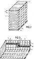
- la figure 2 est une vue en perspective d'un condensateur constitué de plusieurs éléments capacitifs avant shoopage ;
- la figure 3 est une vue en perspective d'un condensateur tel que représenté à la figure 2 après câblage des différents éléments capacitifs, et
- la figure 4 est une vue en coupe montrant les éléments capacitifs à l'intérieur d'une cuve.
- On décrira donc en se référant aux figures 1 à 4 un mode de réalisation préférentiel d'un condensateur de puissance conforme à la présente invention.
- Comme représenté sur la figure 1A, le ou les éléments capacitifs constituant le condensateur de puissance sont obtenus par bobinage autour d'une broche M d'au moins deux films 1 présentant des zones métallisées 2 et sur leurs bords opposés des marges 3 non métallisées. Le film métallisé utilisé dans le cadre de la présente invention est un film polymère, plus particulièrement un film de polypropylène bi-orienté. Pour permettre une imprégnation ultérieure, le film de polypropylène est de préférence, comme représenté sur la figure 1B, un film rugueux. Il peut être rugueux sur une face ou rugueux sur les deux faces. De manière connue, ce film, prétraité corona, a été métallisé en utilisant un métal tel que l'aluminium dans un appareil de métallisation sous vide (résistivité de la métallisation 1 à 5 Ω □).
- D'autre part, pour obtenir les résultats souhaités, notamment au niveau du gradient de fonctionnement, on utilise un film métallisé présentant un crénelage formé par des démétallisations locales du film métallisé. L'utilisation d'un tel crénelage permet entre autres d'améliorer l'autocicatrisation et les résultats de test ont montré que l'on obtenait ainsi un meilleur gradient de fonctionnement nominal.
- Afin de réaliser un shoopage correct sur les tranches de bobines, les deux films métallisés sont bobinés en étant décalés l'un par rapport à l'autre. De plus, un film plastique rugueux non métallisé est inséré entre les deux films sur environ 2 tours en début et en fin de bobinage.
- Conformément à la présente invention, le bobinage est réalisé autour de la broche avec un asservissement continu du foisonnement. Dans le mode de réalisation représenté, cet asservissement sera tel que l'on obtienne un diamètre extérieur de bobine sur le mandrin M correspondant à un foisonnement d'environ 15% par rapport à l'épaisseur pondérale du film métallisé. Par foisonnement, on entend l'inter-espace donné par le bobinage entre les couches. Pour obtenir une bonne imprégnation et de bonnes preformances, le foisonnement doit être le plus constant possible.
- Une fois le bobinage terminé, l'élément capacitif cylindrique C ainsi obtenu est extrait de la broche M, il est aplati et mis en presse à une côte mécanique correspondant à un foisonnement de 12% dans le mode de réalisation représenté de manière à obtenir un élément plat C' tel que représenté sur la figure 2. L'utilisation d'éléments plats permet d'obtenir des éléments dont l'épaisseur e est parfaitement contrôlée, c'est-à-dire des éléments dont le foisonnement est tout à fait déterminé.
- Comme représenté sur la figure 2, pour obtenir un condensateur de puissance présentant une valeur de capacité spécifique, plusieurs éléments plats C′, à savoir huit dans le mode de réalisation représenté sur la figure 2, sont empilés les uns sur les autres. Il sont maintenus entre deux plaques 4 réalisées par exemple en tissu de verre époxy, l'ensemble étant solidarisé par l'intermédiaire de deux bandes plastiques 5 de manière à former un pain cerclé.
- Conformément au procédé de réalisation des condensateurs de puissance de la présente invention, afin de stabiliser mécaniquement le film diélectrique, le pain d'éléments plats est soumis à une cuisson dans une étuve sous-vide. De préférence, cette cuisson est réalisée à une température d'environ 80°C sous un vide inférieur à 10⁻²mm d'Hg. Après avoir atteint la température et le vide désiré, le pain est laissé dans l'étuve pendant 24 heures. Puis, on fait redescendre la température jusqu'à 20°C et on laisse les pains pendant 16 heures avant de les sortir à température ambiante.
- Une fois cette opération réalisée, on prépare les différents éléments plats de manière à pouvoir effectuer le shoopage des terminaisons latérales. Dans le mode de réalisation représenté, le shoopage est réalisé de manière connue par projection d'un métal tel que du zinc sur une surface 6 (épaisseur couche de Zn : 0,6 µm).
- Après le shoopage, on effectue le câblage des différents éléments capacitifs C. Cette opération de câblage est réalisée après nettoyage des pains de manière à éliminer les poussières de zinc. Ce nettoyage a lieu par exemple en envoyant de l'air comprimé à une pression de 4 bars. On réalise alors le câblage proprement dit des différents éléments. Ce câblage est réalisé en soudant tout d'abord un clinquant de cuivre étamé sur la partie médiane qui a pour but de rigidifier l'ensemble du pain. Puis on soude sur chaque élément une tresse de cuivre 9.
- Comme représenté sur la figure 3, les connexions des différents éléments sont réalisées symétriquement en haut et en bas de la médiane pour chaque demi-pain de manière à obtenir une meilleure répartition des courants. Dans ce cas, les éléments capacitifs sont montés en parallèle. Il est évident pour l'homme de l'art que les éléments capacitifs peuvent être montés en parallèle et/ou en série.
- D'autre part, comme représenté sur la figure 3, in fil de connexion 10 est soudé sur la partie 8. Ce fil de connexion est destiné à relier le pain capacitif à la borne de connexion extérieure, comme représenté sur la figure 4.
- Dans le mode de réalisation de la présente invention, avant de réaliser l'imprégnation du pain d'éléments capacitifs ainsi obtenu, on effectue un certain nombre d'essais de régénération. Ces essais à sec permettent d'éliminer les points faibles, d'obtenir une population plus homogène et d'augmenter les rendements finaux. Le premier essai consiste à décharger dans chaque pain une énergie ballast de, par exemple, 62 Joules, qui correspond à la charge sous 500 Volts d'un condensateur de 500µF. Cet essai permet de réaliser le décourt-circuitage.
- Ensuite, on réalise des essais de régénération en tension. Chaque pain est chargé à une tension continue correspondant à un gradient sur le film de, par exemple, 200V/µ. Cette tension est appliquée pendant un temps d'environ 10 secondes. Pendant ce temps, on observe donc un nombre important de régénérations. Si les régénérations ne sont pas stabilisées au bout de 30 secondes, le pain est considéré comme inutilisable.
- Une fois ces essais réalisés, le pain est alors prêt à être monté en cuve comme représenté sur la figure 4. Conformément à la présente invention, on utilise comme cuve un boitier parallélépipèdique métallique, réalisé par exemple en acier, en inox, en aluminium. Le boîtier métallique permet de mettre facilement à la masse le condensateur et est utilisé pour des raisons de sécurité. Comme représenté sur la figure 4, la cuve métallique 11 est garnie intérieurement avec des plaques 12, 13 ainsi qu'une plaque de maintien 14 insérée ultérieurement, réalisés en des matériaux isolants par exemple en polypropylène. Ces plaques en matériaux isolants servent à isoler électriquement le ou les pains par rapport à la cuve. A titre d'exemple, la plaque 13, disposée en fond de cuve, présente une épaisseur de 10mm tandis que les profilés latéraux 12 présentent une épaisseur de 2mm. Ensuite un ou plusieurs pains d'éléments capacitifs C′ sont introduits dans la cuve métallique 11 et sont calés avec un ou plusieurs jeux de plaques 15 réalisées elles aussi en matériaux isolants. Le calage du ou des pains à l'intérieur de la cuve est essentiel pour que les éléments capacitifs supportent les vibrations. La plaque de maintien 14 est ensuite introduite. Deux équerres 16 sont alors soudées en haut de cuve pour immobiliser l'ensemble.
- Ensuite, comme représenté sur la figure 4, la cuve est munie d'un couvercle 17 présentant une ouverture 18 pour le passage des bornes de connexion 19 et l'imprégnation. Une fois les pains capacitifs montés dans la cuve, on réalise alors leur imprégnation. Cette imprégnation est effectuée en utilisant un diélectrique liquide, de préférence un diélectrique de type végétal tel que l'huile de colza qui a pour principal avantage de ne pas abîmer la métallisation et de pénètrer très faiblement le film polypropylène.
- Toutefois, il est évident pour l'homme de l'art que des mélanges huile de colza et liquides de synthèses aromatiques pourraient aussi être utilisés, sous réserve qu'ils ne détériorent pas la métallisation. Des adjuvants tels que anti-oxydant et époxy sont ajoutés dans des préparations inférieures au % ; ces adjuvants, en particulier l'époxy, permettent d'augmenter les durées de vie des condensateurs.
- L'imprégnation se réalise en deux phases. On effectue tout d'abord le séchage du condensateur, de préférence à une température de 50° C sous un vide de 10⁻²mm de mercure. On considère que le condensateur est correctement séché lorsqu'on a atteint le couple 50°C/10⁻²mm d'Hg pendant 24 heures.
- Puis on réalise l'imprégnation proprement dite. Pour cela, on dégaze sous vide, à 60°C, le liquide et on le dépollue sur des matériaux terres ou sur colonne d'alumine activée. Le liquide est alors admis dans la cuve d'imprégnation sous vide à 10 ⁻²mm de mercure. Les pains capacitifs sont alors imprégnés par immersion. On considère que le condensateur est complètement imprégné lorsque l'augmentation de capacité sur huit heures n'excède pas 1%. A ce stade, le vide est cassé sous azote à pression atmosphèrique et la température est alors coupée. Lorsque l'ensemble est refroidi, le liquide est vidé de la cuve et l'on obture le trou d'imprégnation par soudure d'une capsule ou d'un préssostat préréglé à 0,7 bar, un tel système permet de détecter toute augmentation de pression interne due à un défaut quelconque, et contribue alors à une fonction de sécurité.
- Les condensateurs ainsi obtenus sont alors soumis à des contrôles de fin de production de type classique, tels que des essais d'étanchéité, des contrôles électriques à température ambiante et de traitements de finition.
- L'utilisation du procédé de réalisation décrit ci-dessus a donc permis d'obtenir des condensateurs de puissance présentant une énergie spécifique importante, à savoir supérieure à 100 Joules par litre. D'autre part, ces condensateurs peuvent être soumis à des contraintes de vibration.
Claims (9)
- Un condensateur de puissance du type constitué par au moins un élément capacitif obtenu par bobinage d'au moins deux films diélectriques métallisés, caractérisé en ce que le film diélectrique est constitué par un film plastique, en ce que l'élément capacitif est aplati de manière à former un élément plat présentant une épaisseur garantie et en ce que l'élément plat est imprégné par un diélectrique liquide, en ce que le film métallisé présente un crénelage formé par des démétallisations locales du film métallisé.
- Un condensateur selon la revendication 1, caractérisé en ce que le film plastique est un film polymère à surface rugueuse.
- Un condensateur selon l'une quelconque des revendications 1 et 2, caractérisé en ce que le diélectrique liquide est constitué par un diélectrique de type végétal.
- Un condensateur selon la revendication 3, caractérisé en ce que des adjuvants sont ajoutés au diélectrique liquide.
- Un condensateur selon l'une quelconque des revendications 1 à 4, caractérisé en ce qu'il comporte plusieurs éléments capacitifs montés en parallèle ou/et en série.
- Un condensateur selon l'une quelconque des revendications 1 à 5, caractérisé en ce que le ou les éléments capacitifs sont montés dans une cuve métallique avec interposition de cales en matériau isolant.
- Procédé de fabrication d'un condensateur de puissance selon l'une quelconque des revendications 1 à 6, caractérisé par les étapes suivantes :- bobinage sur une broche d'au moins deux films plastiques métallisés de manière à obtenir un élément capacitif cylindrique, le bobinage étant réalisé avec un asservissement continu du foisonnement ;- aplatissement de l'élément cylindrique de manière à former un élément plat présentant une épaisseur prédéterminée ;- étuvage sous vide de l'élément plat ;- shoopage des terminaisons latérales de l'élément plat ;- câblage des connexions ;- mise en cuve et imprégnation de l'élément plat avec un diélectrique liquide.
- Procédé selon la revendication 7, caractérisé en ce que, en début et en fin de bobinage, un film diélectrique non métallisé est inséré entre deux films métallisés.
- Procédé selon l'une quelconque des revendications 7 et 8, caractérisé en ce que plusieurs éléments plats sont placés en parallèle avant l'opération d'étuvage de manière à obtenir la capacité voulue.
Applications Claiming Priority (2)
| Application Number | Priority Date | Filing Date | Title |
|---|---|---|---|
| FR9008227 | 1990-06-29 | ||
| FR9008227A FR2664089B1 (fr) | 1990-06-29 | 1990-06-29 | Condensateur de puissance. |
Publications (2)
| Publication Number | Publication Date |
|---|---|
| EP0465290A1 true EP0465290A1 (fr) | 1992-01-08 |
| EP0465290B1 EP0465290B1 (fr) | 1998-10-07 |
Family
ID=9398161
Family Applications (1)
| Application Number | Title | Priority Date | Filing Date |
|---|---|---|---|
| EP91401635A Expired - Lifetime EP0465290B1 (fr) | 1990-06-29 | 1991-06-18 | Procédé de fabrication d'un condensateur de puissance |
Country Status (7)
| Country | Link |
|---|---|
| EP (1) | EP0465290B1 (fr) |
| AT (1) | ATE172055T1 (fr) |
| DE (1) | DE69130311T2 (fr) |
| ES (1) | ES2121774T3 (fr) |
| FI (1) | FI913178A7 (fr) |
| FR (1) | FR2664089B1 (fr) |
| WO (1) | WO1993011549A1 (fr) |
Cited By (4)
| Publication number | Priority date | Publication date | Assignee | Title |
|---|---|---|---|---|
| WO1993011549A1 (fr) * | 1990-06-29 | 1993-06-10 | Compagnie Europeenne De Composants Electroniques Lcc | Condensateur de puissance |
| EP0598256A1 (fr) * | 1992-11-16 | 1994-05-25 | SIEMENS MATSUSHITA COMPONENTS GmbH & CO. KG | Condensateur électrique à faible inductance pour l'électronique d'énergie |
| FR2701158A1 (fr) * | 1993-01-29 | 1994-08-05 | Lcc Cie Euro Composants Electr | Condensateur de puissance. |
| WO2006024592A1 (fr) * | 2004-08-30 | 2006-03-09 | Siemens Aktiengesellschaft | Condensateur haute tension |
Citations (5)
| Publication number | Priority date | Publication date | Assignee | Title |
|---|---|---|---|---|
| DE1000530B (de) * | 1950-05-05 | 1957-01-10 | Siemens Ag | Elektrischer Kondensator, insbesondere Wickelkondensator |
| US3424957A (en) * | 1967-10-31 | 1969-01-28 | Gen Electric | Electrical capacitor and dielectric material therefor |
| FR2233684A1 (en) * | 1973-06-12 | 1975-01-10 | Gen Electric | Epoxide- stabilised aliphatic acid esters - used as dielectric impregnating liquids pref.in electrical condensers |
| EP0045397A2 (fr) * | 1980-08-01 | 1982-02-10 | Roederstein Spezialfabriken für Bauelemente der Elektronik und Kondensatoren der Starkstromtechnik GmbH | Condensateur bobiné imprégné |
| FR2579366A1 (fr) * | 1985-03-22 | 1986-09-26 | Europ Composants Electron | Condensateur a tres haute energie volumique et auto-cicatrisations controlees |
Family Cites Families (1)
| Publication number | Priority date | Publication date | Assignee | Title |
|---|---|---|---|---|
| FR2664089B1 (fr) * | 1990-06-29 | 1996-04-12 | Europ Composants Electron | Condensateur de puissance. |
-
1990
- 1990-06-29 FR FR9008227A patent/FR2664089B1/fr not_active Expired - Fee Related
-
1991
- 1991-06-18 DE DE69130311T patent/DE69130311T2/de not_active Expired - Fee Related
- 1991-06-18 ES ES91401635T patent/ES2121774T3/es not_active Expired - Lifetime
- 1991-06-18 AT AT91401635T patent/ATE172055T1/de not_active IP Right Cessation
- 1991-06-18 EP EP91401635A patent/EP0465290B1/fr not_active Expired - Lifetime
- 1991-06-28 FI FI913178A patent/FI913178A7/fi unknown
- 1991-11-29 WO PCT/FR1991/000950 patent/WO1993011549A1/fr not_active Ceased
Patent Citations (5)
| Publication number | Priority date | Publication date | Assignee | Title |
|---|---|---|---|---|
| DE1000530B (de) * | 1950-05-05 | 1957-01-10 | Siemens Ag | Elektrischer Kondensator, insbesondere Wickelkondensator |
| US3424957A (en) * | 1967-10-31 | 1969-01-28 | Gen Electric | Electrical capacitor and dielectric material therefor |
| FR2233684A1 (en) * | 1973-06-12 | 1975-01-10 | Gen Electric | Epoxide- stabilised aliphatic acid esters - used as dielectric impregnating liquids pref.in electrical condensers |
| EP0045397A2 (fr) * | 1980-08-01 | 1982-02-10 | Roederstein Spezialfabriken für Bauelemente der Elektronik und Kondensatoren der Starkstromtechnik GmbH | Condensateur bobiné imprégné |
| FR2579366A1 (fr) * | 1985-03-22 | 1986-09-26 | Europ Composants Electron | Condensateur a tres haute energie volumique et auto-cicatrisations controlees |
Cited By (5)
| Publication number | Priority date | Publication date | Assignee | Title |
|---|---|---|---|---|
| WO1993011549A1 (fr) * | 1990-06-29 | 1993-06-10 | Compagnie Europeenne De Composants Electroniques Lcc | Condensateur de puissance |
| EP0598256A1 (fr) * | 1992-11-16 | 1994-05-25 | SIEMENS MATSUSHITA COMPONENTS GmbH & CO. KG | Condensateur électrique à faible inductance pour l'électronique d'énergie |
| FR2701158A1 (fr) * | 1993-01-29 | 1994-08-05 | Lcc Cie Euro Composants Electr | Condensateur de puissance. |
| EP0611179A1 (fr) * | 1993-01-29 | 1994-08-17 | Compagnie Europeenne De Composants Electroniques Lcc | Condensateur de puissance |
| WO2006024592A1 (fr) * | 2004-08-30 | 2006-03-09 | Siemens Aktiengesellschaft | Condensateur haute tension |
Also Published As
| Publication number | Publication date |
|---|---|
| ATE172055T1 (de) | 1998-10-15 |
| WO1993011549A1 (fr) | 1993-06-10 |
| FI913178A7 (fi) | 1991-12-30 |
| FR2664089B1 (fr) | 1996-04-12 |
| DE69130311D1 (de) | 1998-11-12 |
| FI913178A0 (fi) | 1991-06-28 |
| DE69130311T2 (de) | 1999-03-04 |
| ES2121774T3 (es) | 1998-12-16 |
| FR2664089A1 (fr) | 1992-01-03 |
| EP0465290B1 (fr) | 1998-10-07 |
Similar Documents
| Publication | Publication Date | Title |
|---|---|---|
| US5043843A (en) | Film capacitor and method of making the same | |
| JPH0256803B2 (fr) | ||
| US2731706A (en) | Manufacture of capacitors | |
| US3855507A (en) | Self heating capacitors | |
| EP0465290B1 (fr) | Procédé de fabrication d'un condensateur de puissance | |
| EP0162766A1 (fr) | Dispositif de stockage à haute tension et à haute énergie et générateur d'impulsions en comportant application | |
| JPH05251266A (ja) | フィルムコンデンサおよびコンデンサ用メタライズドフィルム | |
| US4170812A (en) | Method of making a dual value capacitor | |
| US1385379A (en) | Electrical condenser and method of making it | |
| JPS6052009A (ja) | 自動再生可能な蓄電器とその製造方法 | |
| US3892023A (en) | Process of manufacturing a capacitor assembly | |
| CA1116706A (fr) | Condensateur electrique avec une partie metallique plissee et une partie enroulee autour des fils conducteurs | |
| US4945449A (en) | High voltage capacitor with high energy density | |
| GB2089569A (en) | Metallized-film Dual Capacitor | |
| EP0611179A1 (fr) | Condensateur de puissance | |
| KR100210560B1 (ko) | 전력콘덴서 | |
| EP0001525A1 (fr) | Condensateurs à film diélectrique plastique et leur procédé de fabrication | |
| FR2659485A1 (fr) | Condensateur a film dielectrique souple metallise et procede de realisation d'un tel condensateur. | |
| US6265058B1 (en) | Polymer/paper capacitor film | |
| US575653A (en) | Electrical condenser | |
| FR2464546A1 (fr) | Condensateur a connexions a micro-bandes | |
| FR2677803A1 (fr) | Procede de fabrication de condensateurs a films de polyethylene naphtalene metallises de type empile ou bobine. | |
| EP0246134A1 (fr) | Condensateur de précision à ajustement de la capacité nominale | |
| FR2553564A1 (fr) | Procede et dispositif correspondant pour ameliorer la rigidite dielectrique d'un isolement pour cables a courant continu | |
| JPH09260209A (ja) | 電力用コンデンサ |
Legal Events
| Date | Code | Title | Description |
|---|---|---|---|
| PUAI | Public reference made under article 153(3) epc to a published international application that has entered the european phase |
Free format text: ORIGINAL CODE: 0009012 |
|
| AK | Designated contracting states |
Kind code of ref document: A1 Designated state(s): AT CH DE DK ES FR GB IT LI NL SE |
|
| 17P | Request for examination filed |
Effective date: 19920125 |
|
| 17Q | First examination report despatched |
Effective date: 19931220 |
|
| GRAG | Despatch of communication of intention to grant |
Free format text: ORIGINAL CODE: EPIDOS AGRA |
|
| GRAG | Despatch of communication of intention to grant |
Free format text: ORIGINAL CODE: EPIDOS AGRA |
|
| GRAG | Despatch of communication of intention to grant |
Free format text: ORIGINAL CODE: EPIDOS AGRA |
|
| GRAH | Despatch of communication of intention to grant a patent |
Free format text: ORIGINAL CODE: EPIDOS IGRA |
|
| RAP1 | Party data changed (applicant data changed or rights of an application transferred) |
Owner name: THOMSON-CSF PASSIVE COMPONENTS |
|
| GRAH | Despatch of communication of intention to grant a patent |
Free format text: ORIGINAL CODE: EPIDOS IGRA |
|
| GRAA | (expected) grant |
Free format text: ORIGINAL CODE: 0009210 |
|
| AK | Designated contracting states |
Kind code of ref document: B1 Designated state(s): AT CH DE DK ES FR GB IT LI NL SE |
|
| PG25 | Lapsed in a contracting state [announced via postgrant information from national office to epo] |
Ref country code: NL Free format text: LAPSE BECAUSE OF FAILURE TO SUBMIT A TRANSLATION OF THE DESCRIPTION OR TO PAY THE FEE WITHIN THE PRESCRIBED TIME-LIMIT Effective date: 19981007 |
|
| REF | Corresponds to: |
Ref document number: 172055 Country of ref document: AT Date of ref document: 19981015 Kind code of ref document: T |
|
| REG | Reference to a national code |
Ref country code: CH Ref legal event code: EP |
|
| REF | Corresponds to: |
Ref document number: 69130311 Country of ref document: DE Date of ref document: 19981112 |
|
| REG | Reference to a national code |
Ref country code: ES Ref legal event code: FG2A Ref document number: 2121774 Country of ref document: ES Kind code of ref document: T3 |
|
| GBT | Gb: translation of ep patent filed (gb section 77(6)(a)/1977) |
Effective date: 19981209 |
|
| PG25 | Lapsed in a contracting state [announced via postgrant information from national office to epo] |
Ref country code: DK Free format text: LAPSE BECAUSE OF FAILURE TO SUBMIT A TRANSLATION OF THE DESCRIPTION OR TO PAY THE FEE WITHIN THE PRESCRIBED TIME-LIMIT Effective date: 19990107 |
|
| NLV1 | Nl: lapsed or annulled due to failure to fulfill the requirements of art. 29p and 29m of the patents act | ||
| PLBE | No opposition filed within time limit |
Free format text: ORIGINAL CODE: 0009261 |
|
| STAA | Information on the status of an ep patent application or granted ep patent |
Free format text: STATUS: NO OPPOSITION FILED WITHIN TIME LIMIT |
|
| 26N | No opposition filed | ||
| REG | Reference to a national code |
Ref country code: GB Ref legal event code: IF02 |
|
| PGFP | Annual fee paid to national office [announced via postgrant information from national office to epo] |
Ref country code: DE Payment date: 20020521 Year of fee payment: 12 |
|
| PGFP | Annual fee paid to national office [announced via postgrant information from national office to epo] |
Ref country code: SE Payment date: 20020522 Year of fee payment: 12 Ref country code: GB Payment date: 20020522 Year of fee payment: 12 |
|
| PGFP | Annual fee paid to national office [announced via postgrant information from national office to epo] |
Ref country code: CH Payment date: 20020605 Year of fee payment: 12 |
|
| PGFP | Annual fee paid to national office [announced via postgrant information from national office to epo] |
Ref country code: ES Payment date: 20020613 Year of fee payment: 12 |
|
| PGFP | Annual fee paid to national office [announced via postgrant information from national office to epo] |
Ref country code: FR Payment date: 20020621 Year of fee payment: 12 |
|
| PGFP | Annual fee paid to national office [announced via postgrant information from national office to epo] |
Ref country code: AT Payment date: 20020627 Year of fee payment: 12 |
|
| PG25 | Lapsed in a contracting state [announced via postgrant information from national office to epo] |
Ref country code: GB Free format text: LAPSE BECAUSE OF NON-PAYMENT OF DUE FEES Effective date: 20030618 Ref country code: AT Free format text: LAPSE BECAUSE OF NON-PAYMENT OF DUE FEES Effective date: 20030618 |
|
| PG25 | Lapsed in a contracting state [announced via postgrant information from national office to epo] |
Ref country code: SE Free format text: LAPSE BECAUSE OF NON-PAYMENT OF DUE FEES Effective date: 20030619 Ref country code: ES Free format text: LAPSE BECAUSE OF NON-PAYMENT OF DUE FEES Effective date: 20030619 |
|
| PG25 | Lapsed in a contracting state [announced via postgrant information from national office to epo] |
Ref country code: LI Free format text: LAPSE BECAUSE OF NON-PAYMENT OF DUE FEES Effective date: 20030630 Ref country code: CH Free format text: LAPSE BECAUSE OF NON-PAYMENT OF DUE FEES Effective date: 20030630 |
|
| PG25 | Lapsed in a contracting state [announced via postgrant information from national office to epo] |
Ref country code: DE Free format text: LAPSE BECAUSE OF NON-PAYMENT OF DUE FEES Effective date: 20040101 |
|
| EUG | Se: european patent has lapsed | ||
| GBPC | Gb: european patent ceased through non-payment of renewal fee |
Effective date: 20030618 |
|
| REG | Reference to a national code |
Ref country code: CH Ref legal event code: PL |
|
| PG25 | Lapsed in a contracting state [announced via postgrant information from national office to epo] |
Ref country code: FR Free format text: LAPSE BECAUSE OF NON-PAYMENT OF DUE FEES Effective date: 20040227 |
|
| REG | Reference to a national code |
Ref country code: FR Ref legal event code: ST |
|
| REG | Reference to a national code |
Ref country code: ES Ref legal event code: FD2A Effective date: 20030619 |
|
| PG25 | Lapsed in a contracting state [announced via postgrant information from national office to epo] |
Ref country code: IT Free format text: LAPSE BECAUSE OF NON-PAYMENT OF DUE FEES;WARNING: LAPSES OF ITALIAN PATENTS WITH EFFECTIVE DATE BEFORE 2007 MAY HAVE OCCURRED AT ANY TIME BEFORE 2007. THE CORRECT EFFECTIVE DATE MAY BE DIFFERENT FROM THE ONE RECORDED. Effective date: 20050618 |