EP0465324A1 - Vorrichtung zum Entfernen der Spitzen von Bohnen - Google Patents
Vorrichtung zum Entfernen der Spitzen von Bohnen Download PDFInfo
- Publication number
- EP0465324A1 EP0465324A1 EP91401774A EP91401774A EP0465324A1 EP 0465324 A1 EP0465324 A1 EP 0465324A1 EP 91401774 A EP91401774 A EP 91401774A EP 91401774 A EP91401774 A EP 91401774A EP 0465324 A1 EP0465324 A1 EP 0465324A1
- Authority
- EP
- European Patent Office
- Prior art keywords
- drum
- longitudinal
- slot
- slots
- successive
- Prior art date
- Legal status (The legal status is an assumption and is not a legal conclusion. Google has not performed a legal analysis and makes no representation as to the accuracy of the status listed.)
- Withdrawn
Links
- 244000046052 Phaseolus vulgaris Species 0.000 title abstract description 18
- 235000010627 Phaseolus vulgaris Nutrition 0.000 title description 16
- 244000013123 dwarf bean Species 0.000 claims description 29
- 238000005192 partition Methods 0.000 claims description 28
- 235000021331 green beans Nutrition 0.000 claims description 19
- 238000009966 trimming Methods 0.000 claims description 10
- 238000011144 upstream manufacturing Methods 0.000 claims description 10
- 239000007787 solid Substances 0.000 claims description 6
- 230000001154 acute effect Effects 0.000 claims description 4
- 235000010582 Pisum sativum Nutrition 0.000 claims description 2
- 240000004713 Pisum sativum Species 0.000 claims description 2
- 239000000109 continuous material Substances 0.000 claims description 2
- 235000013399 edible fruits Nutrition 0.000 claims description 2
- 235000021374 legumes Nutrition 0.000 claims description 2
- 235000005489 dwarf bean Nutrition 0.000 abstract 2
- 235000012431 wafers Nutrition 0.000 description 13
- 238000012423 maintenance Methods 0.000 description 3
- 230000002093 peripheral effect Effects 0.000 description 3
- 230000000694 effects Effects 0.000 description 2
- 239000002184 metal Substances 0.000 description 2
- 230000002349 favourable effect Effects 0.000 description 1
- 238000009434 installation Methods 0.000 description 1
- 238000004519 manufacturing process Methods 0.000 description 1
- 239000000463 material Substances 0.000 description 1
- 230000000149 penetrating effect Effects 0.000 description 1
- 230000035515 penetration Effects 0.000 description 1
- 238000007747 plating Methods 0.000 description 1
- 230000035939 shock Effects 0.000 description 1
- 239000002699 waste material Substances 0.000 description 1
Images

Classifications
-
- A—HUMAN NECESSITIES
- A23—FOODS OR FOODSTUFFS; TREATMENT THEREOF, NOT COVERED BY OTHER CLASSES
- A23N—MACHINES OR APPARATUS FOR TREATING HARVESTED FRUIT, VEGETABLES OR FLOWER BULBS IN BULK, NOT OTHERWISE PROVIDED FOR; PEELING VEGETABLES OR FRUIT IN BULK; APPARATUS FOR PREPARING ANIMAL FEEDING- STUFFS
- A23N15/00—Machines or apparatus for other treatment of fruits or vegetables for human purposes; Machines or apparatus for topping or skinning flower bulbs
- A23N15/12—Machines or apparatus for other treatment of fruits or vegetables for human purposes; Machines or apparatus for topping or skinning flower bulbs for snipping or stringing beans
Definitions
- the present invention generally relates and essentially relates to an improved trimming machine for green beans, fillets or snow peas and for fruits of legumes similar to pods as a new industrial product, a wafer constituting a component element of said machine.
- the invention also relates to the various applications and uses resulting from the use of the aforementioned machine and / or the plate as well as to the various systems, equipment, apparatus, devices and installations which are provided with it.
- a trimming machine of the type comprising a hollow circular cylindrical drum rotating with a longitudinal axis of rotation preferably slightly inclined up and down and from upstream to downstream on the horizontal plane, comprising two coaxial orifices respectively upstream of inlet and downstream of outlet of products at the opposite ends of said drum, a side wall with a smooth external surface traversed by elongated slots, substantially uniform, identical and parallel, spaced in respectively circumferential and longitudinal directions and regularly distributed in being aligned respectively in the two aforementioned directions, and at least one longitudinal row of identical, parallel, parallel, spaced apart external knives, the cutting blades of which are in tangential sliding contact with the smooth convex outer surface of said side wall having their edges sharp incl born on circumferential direction and oriented respectively in opposite direction to the direction of rotation of said drum.
- the two opposite side walls, delimiting each aforementioned slot in the thickness of the radially internal or concave side of the side wall of the aforementioned drum, are inclined respectively in opposite directions relative to each other, so as to converge the one towards the other from the inner or concave face to the outer or convex face towards the lateral edges of the slot located in the convex external surface of the side wall of the drum thus forming a sort of funnel or trough following the proper longitudinal profile of the slot to guide and thus favor the introduction of the beans into the slot.
- the aforementioned slots have their longitudinal extent oriented in a generally circumferential or peripheral direction of the side wall of the drum, therefore in a general direction orthogonal to the axis of rotation of the drum, that is to say to the axis of revolution of the outer cylindrical side wall surface of said drum.
- the side wall of the aforementioned drum is generally constituted by the assembly of identical arcuate rectangular plates, joined juxtaposed in respectively longitudinal and circumferential parallel rows of aligned plates, each plate being curved in its own longitudinal direction and provided with an equal number of slots mentioned above.
- Each slot can be in a wavy or straight configuration.
- the radially internal or concave surface of the side wall of the drum is generally provided with intermediate, transverse, thin, coaxial discs which are substantially planar, parallel, perpendicular to the axis of rotation of the drum, uniformly spaced apart longitudinally, respectively arranged at transverse joint planes between successive circumferential rows of plates and each of which is crossed centrally by an eccentric circular passage opening of relatively large diameter, the respective centers of opening of the successive discs being angularly offset progressively with respect to one another around the axis of rotation of the drum in the direction of rotation thereof, so as to form, in the central region of the machine, a kind of spiral favoring the advancement of the green beans and facilitating the function of introducing the ends green beans in the slots of the wafers in order to trimming, that is to say having their ends out cut by the outer knives.
- These intermediate discs are generally made of thin sheet metal about 1 mm thick.
- the green beans previously introduced into the drum through the upstream orifice and traveling or advancing in the generally longitudinal direction of the drum and initially lying in the lower part of the drum, are drawn upwards.
- drum by the plating effect of the centrifugal force to the point where they will fall back to crash into slots located at the bottom of the drum and substantially opposite to the point where the beans detach from the wall of the drum, this is -to say cease to be driven in rotation by it.
- the penetration force of green beans into the slots is a function of the individual mass of the bean as well as the radius and the speed of rotation of the drum.
- the main object of the invention is to eliminate the aforementioned drawback by modifying the structure of the slits in such a way that the tilting of the green beans is effectively prevented by positive maintenance of each bean in its upright or upright relative position which it takes to the instant he pricks himself in a slit.
- This technical problem is solved in accordance with the invention in a trimming machine of the kind mentioned above by the fact that the aforementioned slots have their longitudinal extent oriented in a direction generally parallel to the axis of rotation of the drum.
- the two opposite lateral walls of each slot are asymmetrical and form, in cross section by a transverse plane perpendicular to the axis of revolution of the drum, an acute re-entrant angle whose sides are unevenly inclined on the trace of the median longitudinal radial plane of the slot, the upstream or rear side, in the direction of rotation of the drum, being less inclined therefore at a steeper slope relative to this trace than the downstream or front side.
- each green bean, pricked in a slit is kept in the most normal position possible on the smooth outer surface of the drum because because of the inertia reaction of the green bean, caused by the movement of rotation of the drum, each green bean is pressed against the steep edge of the slot against which it leans, thus being better supported.
- each aforementioned plate constituting a component part of the side wall of the drum, is thus provided with at least one row of slots parallel to the proper transverse direction of said plate and uniformly spaced in the direction proper longitudinal of said wafer.
- the internal surface of the side wall of the drum is furnished with circumferentially linearly equidistant rows of identical partial planar deflecting partitions, longitudinally aligned along respective generatrices of said side wall and radially projecting inwards, each row extending in the solid wall interval separating two successive longitudinal rows of the aforementioned slots, each deflecting partition being between two successive intermediate discs mentioned above, extending from one disc to another and having a smaller radial width to the corresponding local radial width of the solid annular part of the adjacent disc, so as to form, with the intermediate discs in each compartment delimited between two successive discs, a circumferential series of chambers open inwards.
- This structure is advantageous in that it creates receiving chambers or pockets for green beans to improve the guiding and the maintenance of these in a good trimming position because the green beans, from their introduction into the chambers, will keep a very favorable individual position in cooperation with the new slots to obtain a correct trimming.
- each bean is supported against the steeper rear face of the slot in which it is engaged while being blocked in the latter, the angle of inclination of the front face or opposite on the radial longitudinal median plane of the slot being greater than the angle of inclination of the rear face on this plane to favor the green beans penetrating the slots.
- the deflecting partitions aligned in the same longitudinal row of partitions may consist respectively of separate parts or may form an integral part of a strip of continuous material in one piece passing through each of the successive intermediate discs by a corresponding radial slot in the disc.
- each aforementioned deflecting partition is preferably between a minimum value ensuring good maintenance of the green bean and a maximum value limited so as not to hinder the plunge, fall or descent of the bean in the pocket or receiving chamber of this, delimited between two adjacent deflecting partitions and two successive intermediate discs and, according to yet another characteristic of the invention, each aforementioned deflecting partition has a radial width or height less than the length of the green bean and preferably approximately equal at a value between two thirds and three quarters of the length of a green bean or the like and between two successive deflecting partitions in the circumferential direction there are for example approximately five successive slits.
- the invention also relates to the new industrial product forming a wafer which can be used as a component element of the side wall of a drum of a trimming machine according to the invention and of the type in the form of a portion of a hollow cylinder of revolution, with rectangular outline, arcuate according to own longitudinal direction and with substantially uniform, identical, parallel and equidistant elongated slits, this plate being characterized in that said slits are oriented in proper transverse direction of the plate parallel to the axis of revolution of said cylinder and forms at least one row of slots, which extends in the proper longitudinal direction of the wafer.
- the two opposite lateral walls, delimiting each aforementioned slot in the thickness of the concave side of said plate, are inclined respectively in opposite directions relative to each other, so as to converge l 'towards each other from the concave face to the convex face towards the lateral edges of the slot situated in the externally smooth convex face and, according to another characteristic of the invention, the two opposite lateral walls of each slot are asymmetrical and form, in a straight cross section by a plane perpendicular to the axis of revolution of the aforementioned cylinder, an acute re-entrant angle whose sides are unevenly inclined on the trace of the plane median longitudinal radial of said slot, one of said sides being less inclined therefore at a steeper slope relative to this trace than the other side.
- the present invention therefore constitutes a significant advance over the known state of the prior art by offering the advantage of greatly improved operating efficiency, greatly increased yield and much more economical production. than in the past.
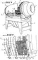
- FIG. 1 represents an overall external perspective view of a trimmer of green beans according to the invention, seen from the side of the upstream end for introducing green beans into the drum.
- FIG. 2 is a fragmentary view on a larger scale of the circled part II of FIG. 1.
- Figure 3 is an isolated segmented view, on an enlarged scale, of the concave face or the radially internal side of a wafer according to the invention, forming a component element of the side wall of the drum of the trimmer of Figure 1 .
- FIG. 4 is a partial view, on a larger scale, in longitudinal section along the line of section IV-IV of FIG. 3.
- FIG. 5 is a cross-sectional view along the line of section V-V in FIG. 3.
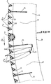
- Figure 6 is a fragmentary perspective view cut through a portion of wafer, on the side of its concave face or radially internal.
- FIG. 7 is a fragmentary perspective view, on a smaller scale, of a portion of the side wall of the trimmer drum, seen from the concave or radially internal side of this wall.
- FIG. 8 represents a partial view, on a larger scale, in cross section along the line of section VIII-VIII of FIG. 7.
- FIG. 9 is a fragmentary view, from the side of its concave or radially internal face, of a plate according to another embodiment of the invention with rectilinear slots.
- the trimming machine comprises a lower frame 2 supporting, in a rotary manner, a generally cylindrical drum of revolution 3 whose longitudinal central axis is slightly inclined up and down and upstream downstream on a horizontal plane.
- This drum comprises, at its two opposite ends, respectively two coaxial orifices, namely: an orifice 4 for introducing products to be treated (in particular of green beans to be cropped) located on the top or upstream side and an orifice 5 for the output of green beans trimmed located on the bottom or downstream side.
- the circular cylindrical side wall 6 of the drum 3 has a smooth outer surface and is formed by the assembly of a multiplicity of identical curved rectangular plates 7 advantageously made of a synthetic or plastic material and juxtaposed contiguously in successive rows extending in respectively circumferential or peripheral and longitudinal directions (in a direction parallel to the axis of revolution of the drum).
- the direction of the proper longitudinal dimension of each plate is oriented in the circumferential direction of the drum.
- each plate is provided, at each of its two ends along its long dimension, with an elongated recess 8 forming a cylindrical groove with a substantially semi-circular straight cross section, s 'extending along the proper width of the wafer, that is to say, in the assembled position of the wafers, parallel to the direction of the axis of revolution of the drum and serving to assemble the wafers to each other by means identical straight rods or rods 9 (see FIGS.
- each aforementioned knife is of a substantially triangular shape with two cutting blades forming two sides of the triangle converging in opposite directions to the direction of rotation of the drum and the respective cutting edges of which are inclined on the generatrices of the cylindrical wall 6 of the drum respectively in opposite longitudinal directions.
- the side wall 6 of the drum 3 of the trimmer is made up of 31 circumferential rows of plates 7, each plate having for example a natural length of 260 mm, a natural width of 58 mm and a thickness 10 mm.
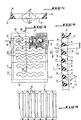
- FIG. 3 represents an isolated view of the concave or hollow face of a wafer according to a currently preferred embodiment of the invention.
- This plate with a smooth convex or convex external surface, has identical parallel transverse slots spaced longitudinally equidistantly 14, for example 21 in number, extending parallel to its width dimension and having their own median longitudinal axes spaced from one another 13 mm for example.
- Each slot is advantageously of wavy configuration, each of the two opposite lateral edges consisting of a series of adjacent notches with an apparent outline in the form of identical re-entrant arcs of circle, separated respectively by rounded projecting teeth with apex in an arc of a circle of radius. significantly smaller, thus giving a serrated appearance to such a side edge.
- the opposite wavy or serrated lateral edge has a number of re-entrant or concave notches and projecting or convex teeth respectively less than one unit than that of the other lateral edge, so that the respective teeth of the two opposite lateral edges are mutually offset in the longitudinal direction with respect to each other so that each projecting or convex tooth on one side edge is substantially opposite a concave notch on the other side edge and vice versa.
- the respective visible contours of the two opposite lateral edges are connected at each end by an arc of a circle of smaller radius than the identical arcs of circle forming the respective notches of the two opposite lateral edges.
- the width of each slot is for example around 4.5 mm.
- each slot 14 is delimited by two opposite lateral walls of corrugated shape corresponding to the corrugated shape of the slot and these two opposite lateral walls are inclined respectively in opposite directions by diverging from one another from the corresponding edges of the slot located in the convex smooth face of the wafer, so that each side wall face of the slot is formed by a series of adjacent concave cylindrical surface portions, successively separated from each other by inclined rounded edges oriented along a common generatrix of two such concave cylindrical surface portions.
- each slot 14 comprises for example a lateral edge 15 formed by five successive circular notches separated respectively by four projecting teeth or convex edges 16 while the opposite lateral edge consists of four successive circular notches 17 separated respectively by three teeth protruding or convex edges 18.
- each solid portion of intermediate wall, separating two successive slots 14 has the appearance of a kind of rib with opposite sides, respectively wavy, forming the adjacent side walls of two slots 14 adjacent and connecting to each other along an edge substantially in the form of a broken line in a substantially regular zig-zag (see FIGS. 6 and 7).
- the opposite longitudinal edges 20 of the plate 7 have a shape of straight cross section approximately in a right triangle ending, on the concave side of the plate, by a chamfered or bevelled portion so as to constitute a longitudinal edge located in the outer longitudinal flat face of the edge of the wafer.
- FIG. 4 shows the smooth convex face 21 of the side wall 6 of the drum, in which the slots 14 are formed as well as the respective different inclinations, in opposite directions, of the two opposite lateral edge faces 16, 17 of each slot 14
- the lateral edge face 17, forming the more abrupt rear side of the slot 14 forms an angle ⁇ of approximately 15 ° with the abovementioned longitudinal longitudinal radial plane of the slot while the other lateral edge face 16 of the slot, forming the more inclined front side thereof, makes an angle b of about 35 ° with said plane, this plane, substantially normal to the smooth external surface 21, which can be materialized by its trace on this surface.
- the concave or radially internal face of the lateral wall 6 of the drum 3 comprises, on the one hand, a series of intermediate discs 24 mounted respectively at the junctions between successive circumferential or peripheral rows of plates 7 and , on the other hand, circumferentially spaced longitudinal rows of aligned deflecting partitions 25 extending respectively between the successive intermediate discs 24 being radially projecting inwards.
- the intermediate discs and the deflecting partitions are advantageously made of metallic sheet metal, the deflecting partitions 25 being oriented substantially along radial planes. These deflecting partitions 25 thus form successive circumferential rows of deflecting partitions which are preferably linearly equidistant in the circumferential direction or angularly spaced uniformly.
- Each deflecting partition 25 is arranged in line with a solid wall gap separating two successive slots 14 in the circumferential direction and there are, for example, five successive slots between two deflecting partitions successive in circumferential direction.
- These deflecting partitions 25, which are substantially planar just like the intermediate discs 24, have a radial width advantageously less than the corresponding local radial width of the intermediate discs 24 which are transversed respectively by eccentric central openings 26 angularly offset successively with respect to the others in the same direction around the axis of rotation of the drum. As shown in FIG. 8, the deflecting partitions 25 have a radial width less than the length of the green beans to be trimmed.
- the deflection partitions 25 can for example be spaced from each other by about 65 mm in the circumferential direction and provision may be made, for example, 31 intermediate discs 24, so that each circumferential row of deflection partitions will comprise for example 48 deflection partitions 25 in thus constituting, with the intermediate discs, for example 1440 aforementioned chambers or pockets 27 for receiving the green beans.
- FIG. 8 shows the relative arrangement of several green beans 23 to be trimmed correctly positioned in three circumferentially successive slots in the side wall of the drum by pressing against a deflecting partition 25 inside a receiving chamber 27.
- FIG. 9 is a view similar to FIG. 3 but showing another geometric embodiment of a plate 7 ′ with rectilinear slots 14 ′ with planar opposite walls and moreover having all the other characteristics and properties of the plate previously described. Two adjacent flat walls, between two successive slits, form a protruding dihedral with a straight edge.
Landscapes
- Life Sciences & Earth Sciences (AREA)
- Chemical & Material Sciences (AREA)
- Engineering & Computer Science (AREA)
- Food Science & Technology (AREA)
- Polymers & Plastics (AREA)
- Apparatuses For Bulk Treatment Of Fruits And Vegetables And Apparatuses For Preparing Feeds (AREA)
Applications Claiming Priority (2)
| Application Number | Priority Date | Filing Date | Title |
|---|---|---|---|
| FR9008630A FR2664133A1 (fr) | 1990-07-06 | 1990-07-06 | Ebouteuse de haricots verts et plaquette formant un element composant de celle-ci. |
| FR9008630 | 1990-07-06 |
Publications (1)
| Publication Number | Publication Date |
|---|---|
| EP0465324A1 true EP0465324A1 (de) | 1992-01-08 |
Family
ID=9398462
Family Applications (1)
| Application Number | Title | Priority Date | Filing Date |
|---|---|---|---|
| EP91401774A Withdrawn EP0465324A1 (de) | 1990-07-06 | 1991-06-28 | Vorrichtung zum Entfernen der Spitzen von Bohnen |
Country Status (2)
| Country | Link |
|---|---|
| EP (1) | EP0465324A1 (de) |
| FR (1) | FR2664133A1 (de) |
Cited By (2)
| Publication number | Priority date | Publication date | Assignee | Title |
|---|---|---|---|---|
| CN103720019A (zh) * | 2013-08-23 | 2014-04-16 | 山东省博兴县龙升食品有限公司 | 一种青刀豆剪角机 |
| CN113975850A (zh) * | 2021-10-26 | 2022-01-28 | 广西甙元植物制品有限公司 | 一种基于藜豆生产左旋多巴的自动化生产设备及工艺 |
Citations (6)
| Publication number | Priority date | Publication date | Assignee | Title |
|---|---|---|---|---|
| US1336991A (en) * | 1920-01-22 | 1920-04-13 | William E Urschel | Apparatus for snipping string-beans |
| US2114730A (en) * | 1935-09-23 | 1938-04-19 | Urschel Joe Richard | Bean snipper |
| US2376062A (en) * | 1943-05-14 | 1945-05-15 | Fmc Corp | Flexible knife mounting for bean snippers |
| US2393461A (en) * | 1943-07-19 | 1946-01-22 | William A Finley | Bean snipping machine |
| FR1257041A (fr) * | 1960-01-28 | 1961-03-31 | élément d'ébouteuse, perfectionnement aux ébouteuses | |
| US2979096A (en) * | 1958-04-07 | 1961-04-11 | Chisholm Ryder Co Inc | Pockets for bean snipper |
-
1990
- 1990-07-06 FR FR9008630A patent/FR2664133A1/fr active Pending
-
1991
- 1991-06-28 EP EP91401774A patent/EP0465324A1/de not_active Withdrawn
Patent Citations (6)
| Publication number | Priority date | Publication date | Assignee | Title |
|---|---|---|---|---|
| US1336991A (en) * | 1920-01-22 | 1920-04-13 | William E Urschel | Apparatus for snipping string-beans |
| US2114730A (en) * | 1935-09-23 | 1938-04-19 | Urschel Joe Richard | Bean snipper |
| US2376062A (en) * | 1943-05-14 | 1945-05-15 | Fmc Corp | Flexible knife mounting for bean snippers |
| US2393461A (en) * | 1943-07-19 | 1946-01-22 | William A Finley | Bean snipping machine |
| US2979096A (en) * | 1958-04-07 | 1961-04-11 | Chisholm Ryder Co Inc | Pockets for bean snipper |
| FR1257041A (fr) * | 1960-01-28 | 1961-03-31 | élément d'ébouteuse, perfectionnement aux ébouteuses |
Cited By (4)
| Publication number | Priority date | Publication date | Assignee | Title |
|---|---|---|---|---|
| CN103720019A (zh) * | 2013-08-23 | 2014-04-16 | 山东省博兴县龙升食品有限公司 | 一种青刀豆剪角机 |
| CN103720019B (zh) * | 2013-08-23 | 2016-10-12 | 山东省博兴县龙升食品有限公司 | 一种青刀豆剪角机 |
| CN113975850A (zh) * | 2021-10-26 | 2022-01-28 | 广西甙元植物制品有限公司 | 一种基于藜豆生产左旋多巴的自动化生产设备及工艺 |
| CN113975850B (zh) * | 2021-10-26 | 2022-11-25 | 广西甙元植物制品有限公司 | 一种基于藜豆生产左旋多巴的自动化生产设备及工艺 |
Also Published As
| Publication number | Publication date |
|---|---|
| FR2664133A1 (fr) | 1992-01-10 |
Similar Documents
| Publication | Publication Date | Title |
|---|---|---|
| FR2834436A3 (fr) | Extracteur de jus de fruits et de legumes | |
| CA2066737C (fr) | Machine et procede pour le traitement en continu de surface d'articles de grosseur reduite | |
| FR2467633A1 (fr) | Dechiqueteur a lames dentees portees par deux arbres tournant en sens contraire | |
| FR2587267A1 (fr) | Ensemble formant lame de scie circulaire | |
| FR2850236A1 (fr) | Tete de coupe debroussailleuse, coupe-bordures ou analogue | |
| EP0230331B1 (de) | Vorrichtung zum Schälen von Lebensmitteln, insbesondere zum Schälen von Nüssen | |
| FR2936935A1 (fr) | Centrifugeuse a haut debit | |
| EP3494803B1 (de) | Maschine zum entrappen von trauben | |
| FR2850238A1 (fr) | Tete de coupe pour debroussailleuse, coupe-bordures ou analogue | |
| EP0465324A1 (de) | Vorrichtung zum Entfernen der Spitzen von Bohnen | |
| FR2850235A1 (fr) | Tete de coupe pour debroussailleuse, coupe-bordures ou analogue | |
| EP0296985B1 (de) | Verfahren zum Behandeln von länglichen Landbauprodukten, wie z.B. Gemüsen, sowie Vorrichtung zur Durchführung des Verfahrens | |
| FR2850239A1 (fr) | Tete de coupe pour debroussailleuse, coupe-bordures ou analogue | |
| EP3898138B1 (de) | Motorisierte küchenmaschine | |
| FR2681807A1 (fr) | Dispositif d'emincage de champignons. | |
| FR2943491A1 (fr) | Disque de labour et engin de labour comportant au moins un train equipe d'un tel disque | |
| FR2850237A1 (fr) | Tete de coupe pour debroussailleuse, coupe-bordures ou analogue | |
| FR3002117A1 (fr) | Machine pour ouvrir les cabosses de cacao et/ou de produits de nature et/ou de constitution equivalente | |
| BE710756A (de) | ||
| FR2903621A1 (fr) | Grille de hachoir | |
| FR2484318A1 (fr) | Dispositif de decoupe de fruits et legumes | |
| EP0165888A1 (de) | Vorrichtung zum positiven Strecken von Teigstücken zum industriellen Herstellen von langen Broten | |
| FR2510025A3 (fr) | Lame pour couteau entrainee par moteur electrique | |
| FR2661351A1 (fr) | Machine et installation de decoupe de produits en plaque, notamment pour la realisation de canapes. | |
| FR2474282A1 (fr) | Machine a ebouter les haricots verts |
Legal Events
| Date | Code | Title | Description |
|---|---|---|---|
| PUAI | Public reference made under article 153(3) epc to a published international application that has entered the european phase |
Free format text: ORIGINAL CODE: 0009012 |
|
| AK | Designated contracting states |
Kind code of ref document: A1 Designated state(s): AT BE CH DE ES GB IT LI NL |
|
| 17P | Request for examination filed |
Effective date: 19920515 |
|
| 17Q | First examination report despatched |
Effective date: 19930730 |
|
| STAA | Information on the status of an ep patent application or granted ep patent |
Free format text: STATUS: THE APPLICATION IS DEEMED TO BE WITHDRAWN |
|
| 18D | Application deemed to be withdrawn |
Effective date: 19931210 |