EP0465330B1 - Scheinwerfer mit mehreren Funktionen, insbesondere für Kraftfahrzeuge - Google Patents
Scheinwerfer mit mehreren Funktionen, insbesondere für Kraftfahrzeuge Download PDFInfo
- Publication number
- EP0465330B1 EP0465330B1 EP91401789A EP91401789A EP0465330B1 EP 0465330 B1 EP0465330 B1 EP 0465330B1 EP 91401789 A EP91401789 A EP 91401789A EP 91401789 A EP91401789 A EP 91401789A EP 0465330 B1 EP0465330 B1 EP 0465330B1
- Authority
- EP
- European Patent Office
- Prior art keywords
- reflector
- radiation
- cut
- headlamp according
- zone
- Prior art date
- Legal status (The legal status is an assumption and is not a legal conclusion. Google has not performed a legal analysis and makes no representation as to the accuracy of the status listed.)
- Expired - Lifetime
Links
- 230000005855 radiation Effects 0.000 claims description 46
- 230000005540 biological transmission Effects 0.000 claims description 7
- 230000003287 optical effect Effects 0.000 claims description 7
- 238000005286 illumination Methods 0.000 claims description 5
- 230000000694 effects Effects 0.000 claims description 3
- 239000011521 glass Substances 0.000 claims description 3
- 239000000463 material Substances 0.000 claims description 2
- 238000006073 displacement reaction Methods 0.000 claims 1
- 238000012216 screening Methods 0.000 description 7
- 230000011664 signaling Effects 0.000 description 4
- 230000000295 complement effect Effects 0.000 description 3
- 238000001429 visible spectrum Methods 0.000 description 3
- GWEVSGVZZGPLCZ-UHFFFAOYSA-N Titan oxide Chemical compound O=[Ti]=O GWEVSGVZZGPLCZ-UHFFFAOYSA-N 0.000 description 2
- 238000010891 electric arc Methods 0.000 description 2
- 238000000926 separation method Methods 0.000 description 2
- 239000012780 transparent material Substances 0.000 description 2
- WFKWXMTUELFFGS-UHFFFAOYSA-N tungsten Chemical compound [W] WFKWXMTUELFFGS-UHFFFAOYSA-N 0.000 description 2
- 229910052721 tungsten Inorganic materials 0.000 description 2
- 239000010937 tungsten Substances 0.000 description 2
- 239000011248 coating agent Substances 0.000 description 1
- 238000000576 coating method Methods 0.000 description 1
- 239000003989 dielectric material Substances 0.000 description 1
- 230000004907 flux Effects 0.000 description 1
- 230000004313 glare Effects 0.000 description 1
- 229910052751 metal Inorganic materials 0.000 description 1
- 239000002184 metal Substances 0.000 description 1
- 150000002739 metals Chemical class 0.000 description 1
- 238000000465 moulding Methods 0.000 description 1
- 230000002441 reversible effect Effects 0.000 description 1
- 230000035939 shock Effects 0.000 description 1
- LIVNPJMFVYWSIS-UHFFFAOYSA-N silicon monoxide Chemical compound [Si-]#[O+] LIVNPJMFVYWSIS-UHFFFAOYSA-N 0.000 description 1
- OGIDPMRJRNCKJF-UHFFFAOYSA-N titanium oxide Inorganic materials [Ti]=O OGIDPMRJRNCKJF-UHFFFAOYSA-N 0.000 description 1
- 239000005341 toughened glass Substances 0.000 description 1
- 238000002211 ultraviolet spectrum Methods 0.000 description 1
- 230000000007 visual effect Effects 0.000 description 1
Images


Classifications
-
- F—MECHANICAL ENGINEERING; LIGHTING; HEATING; WEAPONS; BLASTING
- F21—LIGHTING
- F21V—FUNCTIONAL FEATURES OR DETAILS OF LIGHTING DEVICES OR SYSTEMS THEREOF; STRUCTURAL COMBINATIONS OF LIGHTING DEVICES WITH OTHER ARTICLES, NOT OTHERWISE PROVIDED FOR
- F21V11/00—Screens not covered by groups F21V1/00, F21V3/00, F21V7/00 or F21V9/00
- F21V11/08—Screens not covered by groups F21V1/00, F21V3/00, F21V7/00 or F21V9/00 using diaphragms containing one or more apertures
- F21V11/12—Screens not covered by groups F21V1/00, F21V3/00, F21V7/00 or F21V9/00 using diaphragms containing one or more apertures of slot type
-
- F—MECHANICAL ENGINEERING; LIGHTING; HEATING; WEAPONS; BLASTING
- F21—LIGHTING
- F21S—NON-PORTABLE LIGHTING DEVICES; SYSTEMS THEREOF; VEHICLE LIGHTING DEVICES SPECIALLY ADAPTED FOR VEHICLE EXTERIORS
- F21S41/00—Illuminating devices specially adapted for vehicle exteriors, e.g. headlamps
- F21S41/10—Illuminating devices specially adapted for vehicle exteriors, e.g. headlamps characterised by the light source
- F21S41/14—Illuminating devices specially adapted for vehicle exteriors, e.g. headlamps characterised by the light source characterised by the type of light source
- F21S41/17—Discharge light sources
-
- F—MECHANICAL ENGINEERING; LIGHTING; HEATING; WEAPONS; BLASTING
- F21—LIGHTING
- F21S—NON-PORTABLE LIGHTING DEVICES; SYSTEMS THEREOF; VEHICLE LIGHTING DEVICES SPECIALLY ADAPTED FOR VEHICLE EXTERIORS
- F21S41/00—Illuminating devices specially adapted for vehicle exteriors, e.g. headlamps
- F21S41/60—Illuminating devices specially adapted for vehicle exteriors, e.g. headlamps characterised by a variable light distribution
- F21S41/68—Illuminating devices specially adapted for vehicle exteriors, e.g. headlamps characterised by a variable light distribution by acting on screens
- F21S41/683—Illuminating devices specially adapted for vehicle exteriors, e.g. headlamps characterised by a variable light distribution by acting on screens by moving screens
- F21S41/692—Shields, i.e. screens not creating an image meant to be projected
-
- F—MECHANICAL ENGINEERING; LIGHTING; HEATING; WEAPONS; BLASTING
- F21—LIGHTING
- F21V—FUNCTIONAL FEATURES OR DETAILS OF LIGHTING DEVICES OR SYSTEMS THEREOF; STRUCTURAL COMBINATIONS OF LIGHTING DEVICES WITH OTHER ARTICLES, NOT OTHERWISE PROVIDED FOR
- F21V9/00—Elements for modifying spectral properties, polarisation or intensity of the light emitted, e.g. filters
- F21V9/06—Elements for modifying spectral properties, polarisation or intensity of the light emitted, e.g. filters for filtering out ultraviolet radiation
-
- F—MECHANICAL ENGINEERING; LIGHTING; HEATING; WEAPONS; BLASTING
- F21—LIGHTING
- F21S—NON-PORTABLE LIGHTING DEVICES; SYSTEMS THEREOF; VEHICLE LIGHTING DEVICES SPECIALLY ADAPTED FOR VEHICLE EXTERIORS
- F21S41/00—Illuminating devices specially adapted for vehicle exteriors, e.g. headlamps
- F21S41/30—Illuminating devices specially adapted for vehicle exteriors, e.g. headlamps characterised by reflectors
- F21S41/32—Optical layout thereof
- F21S41/33—Multi-surface reflectors, e.g. reflectors with facets or reflectors with portions of different curvature
- F21S41/334—Multi-surface reflectors, e.g. reflectors with facets or reflectors with portions of different curvature the reflector consisting of patch like sectors
- F21S41/335—Multi-surface reflectors, e.g. reflectors with facets or reflectors with portions of different curvature the reflector consisting of patch like sectors with continuity at the junction between adjacent areas
Definitions
- the present invention relates to a headlamp with several functions, in particular for a motor vehicle, adapted to improve the illumination of road signaling elements.
- a headlamp which includes a cut-off lighting function such as, for example, a so-called crossing function or a so-called anti-fog function.
- the illumination range is reduced and does not make it possible to make the road signal elements visible from a very long distance.
- a first object of the present invention is to create a projector with cut beams which overcomes this drawback.
- Such a projector for example described in patent application DE-A-2,249,930, is intended to be added to the projectors, or to the pairs of projectors, normally fitted to a motor vehicle, in particular to perform the functions of so-called crossing and so-called road lighting.
- a headlamp called a dipped headlamp, which emits a visible light beam below a cut-off line, and which emits an ultra-violet light beam above of this same cut.
- a vehicle equipped with a pair of headlights conforming to this patent application must also comprise a pair of headlights adapted to emit a so-called road beam.
- Patent application WO-A-90/08673 proposes a projector of the aforementioned type, capable moreover of emitting a complete light beam or a light beam with cut-off, a mobile blackout transparent to UV rays being susceptible in one of its positions, to intercept part of the light beam, in order to define the beam cut-off.
- the position of the cut-off is determined by the position of the movable screen.
- any deviation in positioning in particular caused by vibrations or shocks, causes a variation in the cut-off and therefore inadequate, even dangerous, lighting when the headlamp is dazzling.
- the main object of the invention is to overcome this drawback.
- a multifunctional projector is produced, which allows the emission of ultra-violet radiation above a cut-off line when a cut-off projection function is used.
- At least one of the two reflector zones is constituted by a surface capable of generating by itself a beam situated below a cut of generally horizontal orientation, and can be constituted by a surface capable of forming images of the light source whose highest points are located in the vicinity of the cut.
- the cut can be horizontal or delimited by a horizontal half-plane and by a half-plane inclined above the horizontal.
- the other zone of the reflector is preferably constituted by a surface capable of generating a concentrated beam in the vicinity of the optical axis.
- the occultation means can comprise either a single screen for selectively obscuring the visible light rays emanating from the source in the direction of said other zone, or even two screens, at least one of which is transparent to ultraviolet radiation to selectively obscure the visible light rays from the source towards the two areas of the reflector, respectively.
- the screen capable of obscuring the rays emanating from the source in the direction of the first reflector zone can be crossed by at least one small orifice to allow a determined quantity of light to pass in the direction of said first zone.
- the screen or each occultation screen comprises a plate articulated around a horizontal axis secured to a cover of direct light associated with the source, this plate being able to be brought into a position of occultation by a driving source such an electric motor associated with transmission means comprising for example gears and a link.
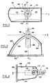
- a projector according to the invention comprises lamp means 100 defining a light source, capable of emitting both radiation in the visible spectrum and in the UV spectrum, a reflector 200 and a closing front window 300.
- the glass 300 is made of a transparent material, at least partially, with ultraviolet radiation.
- the lamp means comprise a discharge lamp, capable of producing between two electrodes an elongated electric arc disposed essentially axially in the vicinity of the optical axis Ox, in a well-known way.
- 102 and 104 are indicated respectively the base and the sealed bulb of the lamp. Its supply terminals are delimited by 108.
- a direct light cover 106 is also provided to avoid the glare of the drivers or pedestrians located in front of the vehicle.
- the cover 106 here has the shape of a cylinder of revolution closed at its front end and whose open rear end has a complex outline such that the rays directed towards optically inoperative parts of the reflector (cheeks, etc.) are intercepted by the cache.
- the cover 106 is opaque to visible light radiation while being advantageously, but not necessarily, at least partially transparent to ultraviolet radiation.
- the reflector 200 is here a reflector of low height and large width, truncated by two upper and lower cheeks 240, 250, essentially horizontal.
- the surface of the reflector 200 is divided into two distinct reflecting zones 210 and 220 capable of emitting two light beams of different types respectively, and this separation is carried out in the present example according to the plan vertical axial x0z of the projector.
- a separation according to two half-planes passing through the optical axis Ox, but of substantial inclination relative to the horizontal, as indicated by the dashed lines P and P ′, is also conceivable. It is thus easy to modify the respective areas of the reflective zones 210, 220, and consequently the intensities of the two beams formed.
- the left zone (in front view) 210 of the reflector may consist of a part of a reflective surface capable of generating by itself, that is to say without the intervention of a concealment mask or the like, the V-cut specific to the standard European passing beam.
- it may be half of an area among those described in French patents and patent applications Nos. 2.536.502, 2.599.121 and 2.609.148 in the name of the Applicant, whose respective contents are incorporated herein by reference, and to which reference will be made for further details.
- the right-hand zone 220 of the reflector is a part of a surface capable of generating a beam essentially complementary to the passing beam. It may, for example, be a portion of a paraboloid with respect to the focal point of which the arc is off-center, or even a half of the surface as described in French patent application No. 2,600,024, the content is also incorporated by reference and to which reference will be made for further details.
- the projector also comprises, as shown diagrammatically in FIGS. 4a and 4b (and not illustrated in FIGS. 1 to 3 for the sake of clarity), a screening screen 420 which here has the shape of a half-cylinder of revolution of horizontal axis essentially coincident with the optical axis, which is articulated by an edge on an axis 440 parallel to the optical axis and located below the lamp, this axis being for example mounted on the direct light cover 106 .
- the occultation screen 420 is opaque to visible light radiation, while being, at least in part, transparent to ultraviolet radiation.
- Drive means can be controlled from the passenger compartment of the vehicle to move the screen 420 between a first position or occluding position (FIG. 4a), in which it is placed against the cache 106 to intercept the radiation from the arc of the lamp towards the area 220 of the reflector, and a second position or erasing position ( Figure 4b), in which it is released from the cover 106, the area 220 now being exposed to radiation. It is observed that, in this example, the zone 210 is always exposed to radiation.
- the ultraviolet radiation also emitted is, at least in part, transmitted through the screen 420, so that the whole of the reflector participates in the reflection of the ultraviolet radiation.
- the whole of the reflector participates in the creation of the beam, so that the latter is constituted by the superposition of the driving beam generated by the area 210 and the complementary beam generated by the area 220, and thus constitutes a driving beam.
- FIGS. 5a to 5d there are diagrammatically illustrated four possibilities of using a headlamp comprising a first reflecting zone 210 such as a surface forming by itself a passing beam and a second reflecting zone 220 in the form of a parabola focused in the vicinity of the arc of the lamp 100.
- Two screening screens 410, 420 for example articulated and mounted on the same axis 440 located below the lamp 100, are respectively associated with the areas 210 and 220 , to selectively expose them to light from the arc or, on the contrary, hide them.
- One of the two blackout screens 410, 420, and alternatively both, is opaque to visible light radiation, while being, at least in part, transparent to ultraviolet radiation.
- This projector is further characterized in that the screening screen 410 assigned to the area 210 of the reflector has one or more small orifices, as indicated in 412, to allow a predetermined quantity of the light emitted by the reflector to pass through. the arc.
- the two screens 410, 420 are in the occultation position, as illustrated, and only a small quantity of the visible light coming from the arc is authorized to exit towards the zone 210, which normally reflects it towards the 'before. This creates a so-called lantern or city lamp function, delivering a small amount of light in front of the vehicle intended for signaling the vehicle more than for lighting the road.
- ultraviolet radiation is advantageously emitted limited or not depending on whether one or the two screens 410, 420 are transparent to ultraviolet radiation.
- FIG. 5b the concealment screen 410 is open. This situation is equivalent to that of FIG. 4a, and the headlamp emits a passing beam.
- FIG. 5c illustrates the case where the blackout screen 410 is closed, while the blackout screen 420 is open. Only the region 220 of the reflector participates in the shape of the beam, so that the beam generated is an ordinary driving beam, concentrated on the optical axis.
- FIG. 5d illustrates a last possibility offered by this reflector: by simultaneously opening the two screens 410, 420, the driving beam and the passing beam are superimposed, in this case obtaining an extremely powerful beam, offering visual comfort both in the distance and closer to the vehicle.
- ultraviolet radiation is emitted, at least in part, above the cut.
- this projector offers four light functions, all of excellent quality, with, in all cases, emission of a long-range ultraviolet radiation, that is to say not limited by any cut, making it possible to make visible road traffic signs, obstacles, mobiles or others, coated with fluorescent elements under the effect of ultraviolet radiation.
- Figures 6a and 6b illustrate a practical embodiment of the concealment means used in the context of the present invention.
- An occulting screen 410 has been illustrated in these figures intended to selectively mask the left-hand part (in front view) 210 of the reflector from the radiation coming from the electric arc.
- a reversible electric motor 401 On a common support (not illustrated), for example integral with the reflector or the projector housing and coming from molding with it, is mounted a reversible electric motor 401 whose output shaft 401a carries a first gear 402. The latter meshes with a reduction gear formed by the gears 403, 404 and 405.
- the final gear 405 carries an eccentric pin 406 on which a first end of a link 407 is articulated.
- the direct light cover 106 here of essentially square cross section, carries on a vertical extension 106a an axis 409 on which the screening screen 410 is articulated by means of a tab 410a.
- a tab 410a AT the free end of the tab 410a, that is to say opposite to the part providing the concealment with respect to the axis 409, is provided an axis 408 on which the other end of the link 407 is articulated.
- a rotation of the motor 401 causes, by means of the transmission constituted by the gears and the link, the passage of the screen 410 from the non-occultation or erasure position, illustrated on the Figure 6a, in the occultation position illustrated in Figure 6b, and vice versa.
- the transmission constituted by the gears and the link
- the passage of the screen 410 from the non-occultation or erasure position, illustrated on the Figure 6a, in the occultation position illustrated in Figure 6b, and vice versa.
- limit switches at an appropriate location of the transmission, or even a servo position control, these two solutions being well known from one skilled in the art.
- the blackout screen 410 has a contour such that, in the blackout position, it seals the entire space between the rear edge of the cover 106 and the base 102 of the lamp, to thus effectively preventing any visible light ray from reaching the reflecting area 210 of the reflector.
- the screening screen can be produced from a tinted glass or tempered glass support on which is deposited at least a thin layer of a material based on oxides of metals, such as titanium oxide (Ti02), silicon oxide (SiO) or, in general, a dielectric material, absorbing the rays of the visible spectrum and allowing, at least in part, the ultra-rays purple.
- a material based on oxides of metals such as titanium oxide (Ti02), silicon oxide (SiO) or, in general, a dielectric material, absorbing the rays of the visible spectrum and allowing, at least in part, the ultra-rays purple.
- the screening screen can also be of the interference band type with a narrow band such as a known filter. under the name of Fabry-Pérot, or be of the diffraction type.
- the present invention by allowing the radiation of the code, road, or even lantern functions, and emission of ultra-violet radiation, makes it possible to achieve substantial savings compared to the systems of the prior art requiring a plurality of projectors.
- the ultraviolet radiation is partly reflected at least by an area of the reflector corresponding to a road lighting function, it makes it possible to considerably increase the efficiency and the range thereof.
- a lamp adapted to emit ultraviolet radiation is mounted near the tungsten filament lamp, the two lamps forming said lamp means.
- any combination of beams other than that which has been indicated above can be envisaged.
- the zone forming the passing beam by a zone forming by itself an anti-fog beam, and responding for example to the surface as described in French patent application No. 2,536,503 in the name of the Applicant, the content of which is incorporated into the present description by reference.
- Another possibility consists in using, for the concealable zone 220, a portion of paraboloid focused on the source and giving a so-called “spot” beam, extremely concentrated, and for the non-concealable zone 210 a surface such as that described in the patent application n ° 2,609,148, generating by itself a beam of road of great width.
- the electromechanical occultation means can be the subject of numerous variants.
- the drive can be performed using an electromagnet instead of the electric motor.
- non-electromechanical occultation means for example an electro-optical screen capable of assuming an opaque state and a transparent state, depending on the value of an electric voltage which is applied across its terminals.
Landscapes
- Engineering & Computer Science (AREA)
- General Engineering & Computer Science (AREA)
- Physics & Mathematics (AREA)
- Spectroscopy & Molecular Physics (AREA)
- Non-Portable Lighting Devices Or Systems Thereof (AREA)
- Lighting Device Outwards From Vehicle And Optical Signal (AREA)
Claims (11)
- Scheinwerfer mit mehreren Funktionen, von denen eine einem abgetrennten Lichtbündel entspricht, insbesondere für Kraftfahrzeuge, zur Verbesserung der Beleuchtung von Straßenbeschilderungselementen, bestehend aus:- Lampenmitteln (100, 104), die eine sichtbare Lichtstrahlung und gleichzeitig eine Ultraviolettstrahlung abgeben,- einem Reflektor (200),- einer Abdeckung (410, 420), die verstellbar zwischen einer Abdeckstellung, in der sie jede sichtbare Lichtstrahlung oberhalb der Abtrennung abfängt, und einer Freigabestellung angebracht ist, in der sie den Durchlaß der sichtbaren Lichtstrahlung im wesentlich unbeeinflußt läßt, wobei diese Abdeckung (410, 420) für die sichtbare Lichtstrahlung undurchlässig ist, während sie für die Ultraviolettstrahlung zumindest teilweise durchlässig ist,- einem vorderseitigen Deckglas (300) aus einem Material, das für die Ultraviolettstrahlung zumindest teilweise durchlässig ist,dadurch gekennzeichnet, daß der genannte Reflektor (200) zwei Bereiche (210, 220) umfaßt, die jeweils zwei verschiedene Lichtbündel erzeugen können, daß diese Bereiche (210, 220) nebeneinander angeordnet sind und sich jeweils über die gesamte Höhe des Reflektors erstrecken, wobei jeder Bereich des Reflektors aus einem Teil einer reflektierenden Fläche besteht, die selbst das jeweilige Lichtbündel erzeugt, und daß die genannte Abdeckung mindestens eine Abdeckkappe (410, 420) umfaßt, die in Abdeckstellung seitlich im Verhältnis zu den genannten Lampenmitteln (100, 104) angeordnet ist, die sich im Innern des Reflektors befinden.
- Scheinwerfer nach Anspruch 1, dadurch gekennzeichnet, daß einer der Bereiche (210) des Reflektors aus einer Fläche besteht, die selbst ein Lichtbündel erzeugen kann, das unterhalb einer insgesamt horizontal ausgerichteten Abtrennung liegt.
- Scheinwerfer nach Anspruch 2, dadurch gekennzeichnet, daß der genannte Bereich (210) aus einer Fläche besteht, die geeignet ist, Bilder der durch die Lampenmittel (100, 104) definierten Lichtquelle zu bilden, deren höchste Punkte in der Nähe der Abtrennung liegen.
- Scheinwerfer nach Anspruch 3, dadurch gekennzeichnet, daß es sich bei der Abtrennung um eine horizontale Abtrennung handelt.
- Scheinwerfer nach Anspruch 3, dadurch gekennzeichnet, daß es sich bei der Abtrennung um eine genormte Abtrennung handelt, die durch eine horizontale Halbebene und eine geneigte Halbebene oberhalb der Horizontalen begrenzt wird.
- Scheinwerfer nach einem der Ansprüche 2 bis 5, dadurch gekennzeichnet, daß der andere Bereich (220) des Reflektors aus einer Fläche besteht, die in der Lage ist, ein konzentriertes Lichtbündel in der Nähe der optischen Achse zu erzeugen.
- Scheinwerfer nach Anspruch 6, dadurch gekennzeichnet, daß die Abdeckmittel eine einzige Abdeckkappe (420) umfassen, die für die sichtbare Lichtstrahlung undurchlässig ist, während sie für die Ultraviolettstrahlung zumindest teilweise durchlässig ist, um selektiv die von der Lichtquelle kommenden sichtbaren Lichtstrahlen in Richtung des besagten anderen Bereichs (220) abzudecken.
- Scheinwerfer nach Anspruch 6, dadurch gekennzeichnet, daß die Abdeckmittel zwei Abdeckkappen (410, 420) umfassen, von denen mindestens eine für die sichtbare Lichtstrahlung undurchlässig ist, während sie für die Ultraviolettstrahlung zumindest teilweise durchlässig ist, um selektiv die von der Lichtquelle kommenden sichtbaren Lichtstrahlen jeweils in Richtung der beiden Bereiche (210, 220) des Reflektors abzudecken.
- Scheinwerfer nach Anspruch 8, dadurch gekennzeichnet, daß in der Abdeckkappe (410) für die Abdeckung der von der Lichtquelle kommenden Strahlen in Richtung des ersten Bereichs (210) des Reflektors mindestens eine kleine Öffnung (412) vorgesehen ist, um eine bestimmte Lichtmenge in Richtung des besagten ersten Bereichs hindurchtreten zu lassen.
- Scheinwerfer nach einem der vorangehenden Ansprüche, dadurch gekennzeichnet, daß die Abdeckkappe bzw. jede Abdeckkappe eine Platte (410, 420) umfaßt, die an einem horizontalen Gelenkbolzen (409) angelenkt ist, der fest an einem mit der Lichtquelle verbundenen Direktlichtschutz (106) angebracht ist, wobei diese Platte durch eine Antriebsquelle (401) in Verbindung mit Übertragungsmitteln (402-408) in eine Abdeckstellung verbracht werden kann.
- Scheinwerfer nach einem der vorangehenden Ansprüche mit einem Direktlichtschutz (106) , dadurch gekennzeichnet, daß der genannte Direktlichtschutz (106) für die sichtbare Lichtstrahlung undurchlässig ist, während er für die Ultraviolettstrahlung zumindest teilweise durchlässig ist.
Applications Claiming Priority (2)
| Application Number | Priority Date | Filing Date | Title |
|---|---|---|---|
| FR9008392 | 1990-07-03 | ||
| FR9008392A FR2664363B1 (fr) | 1990-07-03 | 1990-07-03 | Projecteur a plusieurs fonctions, en particulier pour vehicule automobile, adapte a ameliorer l'eclairement d'elements de signalisation routiere. |
Publications (2)
| Publication Number | Publication Date |
|---|---|
| EP0465330A1 EP0465330A1 (de) | 1992-01-08 |
| EP0465330B1 true EP0465330B1 (de) | 1994-10-12 |
Family
ID=9398280
Family Applications (1)
| Application Number | Title | Priority Date | Filing Date |
|---|---|---|---|
| EP91401789A Expired - Lifetime EP0465330B1 (de) | 1990-07-03 | 1991-07-01 | Scheinwerfer mit mehreren Funktionen, insbesondere für Kraftfahrzeuge |
Country Status (4)
| Country | Link |
|---|---|
| US (1) | US5251110A (de) |
| EP (1) | EP0465330B1 (de) |
| DE (1) | DE69104560T2 (de) |
| FR (1) | FR2664363B1 (de) |
Families Citing this family (22)
| Publication number | Priority date | Publication date | Assignee | Title |
|---|---|---|---|---|
| EP0634306B1 (de) * | 1993-07-16 | 1997-04-09 | Hamamatsu Photonics K.K. | Lichtbestrahlungseinrichtung |
| US5528475A (en) * | 1993-12-24 | 1996-06-18 | Koito Manufacturing Co., Ltd. | Control circuit for automobile headlamps emitting light in variable color |
| FR2715899A1 (fr) * | 1994-02-04 | 1995-08-11 | Barlette Pierre | Eclairage de phares antibrouillard par l'emploi de la lumière noire à rayons ultra-violets ou lumière de Wood. |
| JP3791626B2 (ja) * | 1995-12-22 | 2006-06-28 | 株式会社小糸製作所 | 車輌用前照灯 |
| JP3195215B2 (ja) * | 1995-12-28 | 2001-08-06 | 株式会社小糸製作所 | 自動車用ヘッドランプ |
| DE19756437A1 (de) * | 1997-12-18 | 1999-06-24 | Bosch Gmbh Robert | Scheinwerfer für Fahrzeuge für Abblendlicht und Fernlicht |
| DE19824053A1 (de) * | 1998-05-29 | 1999-12-02 | Hella Kg Hueck & Co | Beleuchtungseinrichtung für Fahrzeuge |
| WO2001036871A1 (en) * | 1999-11-18 | 2001-05-25 | Morpheus Technologies, Llc | Light projector |
| FR2808867B1 (fr) * | 2000-05-11 | 2002-08-23 | Valeo Vision | Projecteur bi-fonction a source lumineuse unique et occulteur mobile pour vehicule automobile |
| FR2826708B1 (fr) * | 2001-06-28 | 2004-03-12 | Valeo Vision | Projecteur d'eclairage de vehicule automobile comportant des volets mobiles |
| US20040213010A1 (en) * | 2003-04-22 | 2004-10-28 | Guide Corporation | Bi-functional headlamp having a linear shifting sleeve with integral actuator |
| GB2438637A (en) | 2006-05-31 | 2007-12-05 | Jacob Dyson | Active lighting system having automatically changing light effect. |
| DE102009002101A1 (de) | 2009-04-01 | 2010-10-14 | Robert Bosch Gmbh | Verfahren und Vorrichtung zur Ausleuchtung von Fahrbahnseitenbereichen |
| US9165756B2 (en) | 2011-06-08 | 2015-10-20 | Xenex Disinfection Services, Llc | Ultraviolet discharge lamp apparatuses with one or more reflectors |
| US9093258B2 (en) | 2011-06-08 | 2015-07-28 | Xenex Disinfection Services, Llc | Ultraviolet discharge lamp apparatuses having optical filters which attenuate visible light |
| GB2527964B (en) * | 2012-01-30 | 2016-03-02 | Xenex Disinfection Services Llc | Ultraviolet discharge lamp apparatuses with multi-paneled optical filters |
| AU2012396233B2 (en) | 2012-12-06 | 2017-09-28 | Xenex Disinfection Services, Llc | Systems which determine operating parameters and disinfection schedules for germicidal devices and germicidal lamp apparatuses including lens systems |
| FR3046835B1 (fr) | 2016-01-20 | 2020-02-14 | Aml Systems | Projecteur pour vehicule automobile a surface de coupure mobile reduite. |
| CZ2021112A3 (cs) * | 2021-03-10 | 2022-04-27 | Varroc Lighting Systems, s.r.o. | Světelné zařízení vozidla k zajištění tmavého, případně barevného vzhledu, alespoň části světelného zařízení ve zhasnutém stavu |
| US20240363327A1 (en) * | 2023-04-28 | 2024-10-31 | Applied Materials, Inc. | Epi thermal profile tuning with lamp radiation shields |
| US12352410B2 (en) * | 2023-11-27 | 2025-07-08 | Robe Lighting S.R.O. | Coating for a framing shutter for a luminaire |
| US12698103B2 (en) | 2025-01-14 | 2026-08-04 | International Business Machines Corporation | Harnessing waste heat of spacecraft to transmit data |
Family Cites Families (24)
| Publication number | Priority date | Publication date | Assignee | Title |
|---|---|---|---|---|
| US1205224A (en) * | 1915-07-22 | 1916-11-21 | Alexander Morecraft | Antiflare device. |
| US1289244A (en) * | 1918-04-22 | 1918-12-31 | Otho M Otte | Reflector cut-off for headlights. |
| US1591992A (en) * | 1924-07-17 | 1926-07-13 | Max J Nave | Headlight dimmer |
| US1562715A (en) * | 1924-10-27 | 1925-11-24 | Auto Light Control Company | Dimmer for headlights |
| FR690678A (fr) * | 1930-02-26 | 1930-09-24 | Disposition d'écran mobile pour phares de véhicules automobiles | |
| US2139707A (en) * | 1936-02-27 | 1938-12-13 | John W Van Denburg | Headlight system |
| US2208079A (en) * | 1939-04-11 | 1940-07-16 | Nosal Mark | Dimming device |
| US2204430A (en) * | 1939-09-05 | 1940-06-11 | Carroll H Montague | Antiglare device for headlights |
| FR1296036A (fr) * | 1961-05-04 | 1962-06-15 | Projecteur à double faisceau faisant utilisation d'une source lumineuse axiale | |
| FR2239862A1 (en) * | 1973-08-01 | 1975-02-28 | Cibie Projecteurs | Full or dipped beam vehicle headlamp - pivotal screen is moved by relative movement of lamp and reflector |
| FR2460442A1 (fr) * | 1979-06-29 | 1981-01-23 | Cibie Projecteurs | Nouvelle structure de projecteur, notamment de projecteur d'automobile |
| DE3113964C2 (de) * | 1981-04-07 | 1984-02-23 | Westfälische Metall Industrie KG Hueck & Co, 4780 Lippstadt | "Innenleuchte für Fahrzeuge" |
| EP0084934A1 (de) * | 1982-01-16 | 1983-08-03 | LUCAS INDUSTRIES public limited company | Lampenreflektor |
| FR2536502B1 (fr) * | 1982-11-19 | 1987-01-09 | Cibie Projecteurs | Projecteur de croisement pour vehicule automobile |
| FR2536503B1 (fr) * | 1982-11-19 | 1987-12-31 | Cibie Projecteurs | Projecteur antibrouillard pour vehicule automobile |
| JPS59119532A (ja) * | 1982-12-25 | 1984-07-10 | Tdk Corp | 磁気記録媒体 |
| FR2566878B1 (fr) * | 1984-06-27 | 1986-07-18 | Cibie Projecteurs | Perfectionnements aux projecteurs automobiles emettant un faisceau coupe, notamment un faisceau de croisement |
| FR2602305B1 (fr) * | 1986-08-04 | 1990-03-23 | Cibie Projecteurs | Projecteur antibrouillard a filament transversal pour vehicule automobile |
| SE458594B (sv) * | 1987-10-22 | 1989-04-17 | Labino Patent Ab | Straalkastare foer fordon |
| JPH0636321B2 (ja) * | 1988-02-02 | 1994-05-11 | 株式会社小糸製作所 | 自動車用灯具 |
| GB8824206D0 (en) * | 1988-10-15 | 1988-11-23 | Carello Lighting Plc | Motor vehicle headlamp |
| FR2642145B1 (fr) * | 1989-01-23 | 1993-04-09 | Valeo Vision | Projecteur de vehicule automobile comportant une source lumineuse unique et engendrant deux faisceaux differents |
| SE466251B (sv) * | 1989-01-24 | 1992-01-20 | Labino Patent Ab | Avblaendningsbar straalkastare foer fordon |
| US5023758A (en) * | 1989-11-13 | 1991-06-11 | General Electric Company | Single arc discharge headlamp with light switch for high/low beam operation |
-
1990
- 1990-07-03 FR FR9008392A patent/FR2664363B1/fr not_active Expired - Lifetime
-
1991
- 1991-06-28 US US07/722,659 patent/US5251110A/en not_active Expired - Fee Related
- 1991-07-01 EP EP91401789A patent/EP0465330B1/de not_active Expired - Lifetime
- 1991-07-01 DE DE69104560T patent/DE69104560T2/de not_active Expired - Fee Related
Also Published As
| Publication number | Publication date |
|---|---|
| FR2664363B1 (fr) | 1992-12-31 |
| EP0465330A1 (de) | 1992-01-08 |
| DE69104560T2 (de) | 1995-02-16 |
| FR2664363A1 (fr) | 1992-01-10 |
| US5251110A (en) | 1993-10-05 |
| DE69104560D1 (de) | 1994-11-17 |
Similar Documents
| Publication | Publication Date | Title |
|---|---|---|
| EP0465330A1 (de) | Scheinwerfer mit mehreren Funktionen, insbesondere für Kraftfahrzeuge | |
| EP0380396B1 (de) | Scheinwerfer für Kraftfahrzeuge mit einer einzigen Lichtquelle zum Erzeugen von zwei verschiedenen Lichtbündeln | |
| EP1308669A1 (de) | Kfz-Scheinwerfer nach dem Projektionsprinzip | |
| EP0227516B2 (de) | Fahrzeugleuchte mit Doppelwirkung | |
| FR2855247A1 (fr) | Phare de vehicule a source, reflecteur et lentille | |
| FR2824623A1 (fr) | Phare de vehicule a diagramme composite de distribution de lumiere | |
| FR2831944A1 (fr) | Phare de vehicule et unite a lampe pour un tel phare | |
| EP1564482B1 (de) | Kfz-Scheinwerfer nach dem Projektionsprinzip umfassend eine Blende aus lichtdurchlässigem Material | |
| FR2819040A1 (fr) | Composant d'optique ou de style pour dispositif d'eclairage ou de signalisation pour vehicule automobile | |
| FR2797680A1 (fr) | Phare pour vehicule | |
| FR2888916A1 (fr) | Module optique pour dispositif d'eclairage automobile | |
| FR2600024A1 (fr) | Projecteur additionnel a un projecteur de croisement pour vehicule automobile | |
| EP3396237B1 (de) | Leuchtmodul für kraftfahrzeug | |
| FR2704044A1 (fr) | Projecteur du genre elliptique pour véhicule automobile. | |
| EP1806531B1 (de) | Multifunktionales, elliptisches Scheinwerfergerät mit zusätzlichem, optischem Element | |
| EP2006604B1 (de) | Optisches Modul für Beleuchtungseinrichtung für Fahrzeuge | |
| FR2810934A1 (fr) | Projecteur elliptique a modification de faisceau par mouvement d'elements optiques | |
| FR2793542A1 (fr) | Projecteur du genre elliptique a deux fonctions d'eclairage pour vehicule automobile | |
| FR2808867A1 (fr) | Projecteur bi-fonction a source lumineuse unique et occulteur mobile pour vehicule automobile | |
| EP1526038B1 (de) | Doppelfunktionsscheinwerfereinrichtung für Kfz | |
| EP1344975B1 (de) | Optisches oder gestalterisches Bauelement für eine Beleuchtungs- oder Anzeigevorrichtung für Kraftfahrzeuge | |
| EP1400748A1 (de) | Kfz-Scheinwerfer mit einem Spiegel und dazu konjugiertem Umlenkelement zur Erzeugung eines Lichtbündels mit einer nicht horizontalen Hell-Dunkelgrenze | |
| FR2789474A1 (fr) | Projecteur du genre elliptique pour vehicule automobile, susceptible d'engendrer selectivement l'un parmi deux types de faisceaux | |
| EP1288563A1 (de) | Beleuchtungseinrichtung zur Erzeugung eines Lichtbündels für den Verkehr bei Regenwetter | |
| FR2818210A1 (fr) | Projecteur tournant pour vehicule automobile comportant une lampe a deux sources |
Legal Events
| Date | Code | Title | Description |
|---|---|---|---|
| PUAI | Public reference made under article 153(3) epc to a published international application that has entered the european phase |
Free format text: ORIGINAL CODE: 0009012 |
|
| AK | Designated contracting states |
Kind code of ref document: A1 Designated state(s): DE ES GB IT SE |
|
| 17P | Request for examination filed |
Effective date: 19920317 |
|
| 17Q | First examination report despatched |
Effective date: 19931004 |
|
| GRAA | (expected) grant |
Free format text: ORIGINAL CODE: 0009210 |
|
| AK | Designated contracting states |
Kind code of ref document: B1 Designated state(s): DE ES GB IT SE |
|
| PG25 | Lapsed in a contracting state [announced via postgrant information from national office to epo] |
Ref country code: IT Free format text: LAPSE BECAUSE OF FAILURE TO SUBMIT A TRANSLATION OF THE DESCRIPTION OR TO PAY THE FEE WITHIN THE PRESCRIBED TIME-LIMIT;WARNING: LAPSES OF ITALIAN PATENTS WITH EFFECTIVE DATE BEFORE 2007 MAY HAVE OCCURRED AT ANY TIME BEFORE 2007. THE CORRECT EFFECTIVE DATE MAY BE DIFFERENT FROM THE ONE RECORDED. Effective date: 19941012 Ref country code: GB Effective date: 19941012 Ref country code: ES Free format text: THE PATENT HAS BEEN ANNULLED BY A DECISION OF A NATIONAL AUTHORITY Effective date: 19941012 |
|
| REF | Corresponds to: |
Ref document number: 69104560 Country of ref document: DE Date of ref document: 19941117 |
|
| EAL | Se: european patent in force in sweden |
Ref document number: 91401789.2 |
|
| GBV | Gb: ep patent (uk) treated as always having been void in accordance with gb section 77(7)/1977 [no translation filed] |
Effective date: 19941012 |
|
| PLBE | No opposition filed within time limit |
Free format text: ORIGINAL CODE: 0009261 |
|
| STAA | Information on the status of an ep patent application or granted ep patent |
Free format text: STATUS: NO OPPOSITION FILED WITHIN TIME LIMIT |
|
| 26N | No opposition filed | ||
| PGFP | Annual fee paid to national office [announced via postgrant information from national office to epo] |
Ref country code: SE Payment date: 20000621 Year of fee payment: 10 |
|
| PGFP | Annual fee paid to national office [announced via postgrant information from national office to epo] |
Ref country code: DE Payment date: 20000711 Year of fee payment: 10 |
|
| PG25 | Lapsed in a contracting state [announced via postgrant information from national office to epo] |
Ref country code: SE Free format text: LAPSE BECAUSE OF NON-PAYMENT OF DUE FEES Effective date: 20010702 |
|
| EUG | Se: european patent has lapsed |
Ref document number: 91401789.2 |
|
| PG25 | Lapsed in a contracting state [announced via postgrant information from national office to epo] |
Ref country code: DE Free format text: LAPSE BECAUSE OF NON-PAYMENT OF DUE FEES Effective date: 20020501 |